1968 DATSUN 510 compression ratio
[x] Cancel search: compression ratioPage 9 of 252

4
CHAPTER
ONE
chassIs
number
Write
the
numbers
down
and
carry
them
ill
your
wallet
Service
Hints
Throughout
thIs
manual
keep
two
conven
bons
ill
mmd
Front
refers
to
the
front
of
the
vehicle
The
left
and
nght
sides
of
the
ve
hicle
refer
to
a
person
sittIng
ill
the
car
facing
forward
For
example
the
steenng
wheelIS
on
the
left
hand
Side
All
dimensIOns
and
capacities
are
expressed
ill
units
fanuhar
to
a
Umted
States
mechaniC
such
as
illches
and
pounds
Metric
measurements
are
also
given
Metnc
tools
are
reqUITed
to
work
on
the
Datsun
CD
DATSUN
IENGINE
CAPACITY
IMAX
HP
RPM
IWHEELBASE
IENGINE
NUMBER
FAR
NO
NlSSAN
MOTOR
co
LTD
YOKOHAMA
JAPAN
TYPEI
510
1595
cc
961P
6600
rpm
mm
L
1
00988
P61
l
O
1
l
M
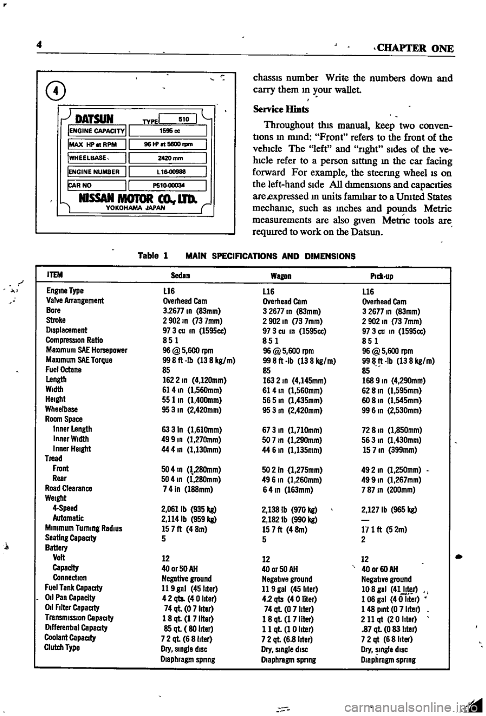
Table
1
MAIN
SPECIFICATIONS
AND
DIMENSIONS
r
ITEM
Sedan
Wagon
Plm
up
EnglDe
Type
L16
L16
L16
Valve
Arrangement
Overhead
Cam
Overhead
Cam
Overhead
Cam
Bore
3
26n
ID
83mm
3
2677
ID
83mm
3
2677
ID
83mm
Stroke
2902
ID
73
7mm
2
902
ID
73
7mm
2
902
In
73
7mm
Displacement
97
3
cu
ID
l595cc
97
3
cu
In
l595cc
97
3
cu
ID
1595cc
CompressIOn
Ratio
851
851
851
MaXimum
SAE
Hompower
96
@
5
600
rpm
96
@
5
600
rpm
96
@
5
600
rpm
MaXimum
SAE
Torque
998ft
Ib
138
kg
m
998ft
Ib
138
kg
m
9911
ft
Ib
138
kg
m
Fuel
Octane
85
85
85
Lengtb
1622
ID
4
12Omm
163
2
ID
4
I45mm
168
9
ID
4
290mm
Width
61
4
ID
l
560mm
61
4
ID
1
560mm
62
8
In
Cl
595mm
Height
55
lID
1
400mm
565
ID
Cl
435mm
60
8
ID
Cl
545mm
Wheelbase
95
3
ID
2
42Omm
95
3
ID
2
420mm
99
6
In
2
530mm
Room
Space
Inner
Length
63
3
In
1
61Omm
673
ID
1
710mm
72
8
ID
1
850mm
Inner
Width
499
ID
1
27Omm
507
ID
1
29Omm
563
In
1
430mm
Inner
Height
44
4
In
1
130mm
44
61D
1
135mm
15
7
ID
399mm
Tread
Front
50
4
ID
28Omm
502
In
1
275mm
492
In
1
250mm
Rear
504
In
1
280mm
496
In
Cl
260mm
499
ID
1
267mm
Road
Clearance
741n
l88mm
64
ID
l63mm
787
ID
200mm
Weight
4
Speed
2
0611b
935
kg
2
138
Ib
970
kg
2
127
Ib
965
kg
Automatic
2
114Ib
959
kg
2
182
Ib
990
kg
Minimum
Turning
RadiUS
157ft
48m
157ft
48m
171
ft
52m
Seating
Capaaty
5
5
2
Battery
Volt
12
12
12
Capacity
400rSOAH
400r50AH
40
or
60
AH
Connection
Negative
ground
Negative
ground
Negative
ground
Fuel
Tank
Capaaty
11
9
gal
45
liter
11
9
gal
45
liter
108
gal
41J
r
011
Pan
Capacity
42
qts
40
liter
4
2
qb
40
liter
1
06
gal
40
Iller
011
Filter
Capaaty
74
ql
07
liter
74
ql
0
7
liter
1
48
Pint
0
7
liter
Transmission
Capaaty
1
8
ql
1
7
liter
18
ql
1
7
Iller
2
11
qt
20
Iller
Dlflerenbal
Capaaty
85
ql
80
liter
11
ql
1
0
liter
87
ql
0
83
lIter
Coolant
Capaaty
7
2
ql
6
8
liter
7
2
ql
6
8
lIter
7
2
qt
6
8
Iller
Clutch
Type
Dry
Single
diSC
Dry
slDgle
diSC
Dry
slDgle
diSC
Draphragm
spnng
Diaphragm
spnng
Diaphragm
spnng
l
Page 18 of 252

TROUBLESHOOTING
13
trouble
may
also
be
worn
bearings
Remove
the
alternator
and
repair
ENGINE
These
procedures
assume
the
starter
cranks
the
engme
over
normally
If
not
refer
to
Starter
section
m
this
chapter
1
Engme
won
t
start
Could
be
caused
by
the
IgOltlon
or
fuel
problems
First
determine
If
high
voltage
to
spark
plug
occurs
To
do
thiS
dISconnect
one
of
the
spark
plug
wires
Hold
the
exposed
wrre
termlOal
y
to
Y2
lOch
from
ground
any
metal
in
engine
com
partment
With
an
msulated
screwdriver
Crank
the
engme
over
If
sparks
do
not
Jump
to
ground
or
the
sparks
are
very
weak
the
trouble
may
be
10
the
IgnitIOn
system
See
Ignition
System
Trou
bleshootmg
to
further
check
If
sparks
occur
properly
the
trouble
may
be
10
the
fuel
system
See
Fuel
System
Troubleshootmg
2
Engme
misses
steadily
Remove
one
spark
plug
wrre
at
a
tune
and
ground
the
wrre
If
engme
mISs
increases
that
cyhnder
was
work
109
properly
Reconnect
the
wire
and
check
the
others
When
a
wire
IS
dIs
connected
and
engme
miss
remams
the
same
that
cylinder
IS
not
finng
Check
spark
as
descnbed
10
Step
1
If
no
spark
occurs
for
one
cyhnder
only
check
dlStnbutor
cap
wrre
and
spark
plug
If
spark
occurs
prop
erly
check
compressIOn
and
mtake
maOlfold
vacuum
to
ISolate
the
trouble
3
Engme
misses
erratlcally
at
all
speeds
Interrmttent
trouble
can
be
difficult
to
find
It
could
be
ill
the
Ignition
system
exhaust
system
or
fuel
system
Follow
troubleshooting
proce
dures
for
these
systems
carefully
to
isolate
the
trouble
4
Engme
misses
at
Idle
only
Trouble
could
exist
anywhere
ill
IgOltlon
system
Follow
Ignition
TroubleshootlOg
procedure
care
fully
Trouble
could
also
eXist
10
the
carburetor
Idle
crrcult
Check
Idle
mIXture
adjustment
and
check
for
restnctions
m
the
idle
crrcUlt
5
Engme
misses
at
high
speed
only
Problems
could
be
ill
the
fuel
or
IgOltlon
systems
heck
accelerator
pump
operation
fuel
pump
dehvery
fuel
hnes
etc
as
descnbed
under
Fuel
System
Troubleshootillg
Also
check
spark
plugs
and
wrres
6
Low
performance
at
all
speeds
poor
acceleratIOn
Trouble
usually
ill
IgOltlon
or
fuel
system
Check
each
With
the
appropnate
troubleshooting
pro
cedure
7
ExceSSive
fuel
consumptIOn
Could
be
caused
by
a
Wide
variety
of
seemmgly
unrelated
factors
Check
for
clutch
shppage
brake
drag
defective
wheel
beanngs
or
poor
front
end
alignment
Check
IgOltlOn
system
and
fuel
system
8
011
pressure
lamp
does
not
light
when
IgmtlOn
switch
IS
on
Check
the
alternator
warning
lamp
If
it
ISn
t
on
either
go
to
Step
1
Chargmg
System
Trouble
shootlOg
If
only
the
oil
pressure
lamp
IS
off
open
the
englOe
compartment
hd
and
locate
the
oil
pressure
sender
on
the
block
near
the
oil
filter
Make
sure
the
wrre
is
connected
to
the
sender
and
makmg
good
contact
Pull
the
wrre
off
and
ground
it
If
the
lamp
hghts
replace
the
sender
If
the
lamp
does
not
light
replace
the
lamp
9
011
pressure
lamp
lights
or
flickers
when
engme
IS
runmng
Indicates
low
or
complete
loss
of
oil
pressure
Stop
the
englOe
unmedmtely
coast
to
a
stop
With
the
clutch
dISengaged
Tlus
may
simply
be
caused
by
a
low
oil
level
or
an
overheatmg
en
glOe
Check
the
oil
level
and
fan
belt
tensIOn
Check
for
a
shorted
oil
pressure
sender
with
an
ohmmeter
or
a
contlOulty
tester
Remove
and
clean
the
oil
dipstick
and
check
oil
level
and
condition
RepleOlsh
or
replace
the
oil
as
re
qurred
Listen
for
unusual
nOISes
mdlcatmg
dam
aged
beanngs
etc
Do
not
re
start
the
engine
until
you
know
why
the
hght
went
on
and
are
sure
that
the
problem
has
been
corrected
IGNITION
SYSTEM
This
procedure
assumes
the
battery
IS
ill
good
enough
condition
to
crank
the
engme
at
a
normal
rate
Page 25 of 252

CHAPTER
FOUR
ENGINE
AND
IGNITION
TUNE
UP
For
best
performance
and
economy
care
must
be
taken
in
perfornnng
tune
ups
While
accuracy
is
required
the
task
IS
not
d1flicult
if
the
steps
m
tlus
chapter
are
followed
carefully
Cars
used
pnmarily
m
CIty
stop
and
go
dnv
ing
WIll
reqwre
attention
more
frequently
than
those
used
on
highways
ThIs
is
because
the
engme
does
not
reach
full
operatIng
temperature
ConsequentlY
valves
tend
to
stick
compression
drops
and
engme
operatIon
becomes
rough
A
tune
up
IS
adVISable
every
6
000
miles
or
sooner
dependmg
on
type
of
driving
Every
12
000
nu1es
the
spark
plugs
and
ignitIon
break
er
pomts
should
be
replaced
not
Just
cleaned
and
adjusted
A
mmor
tune
up
consISts
of
checking
battery
condItIon
cleanmg
gapping
or
replacmg
spark
plugs
and
dIstnbutor
breaker
pomts
adjustIng
dIStnbutor
dwell
angle
adjusting
IgnitIon
tun
mg
and
settIng
the
carburetor
Idle
mixture
and
idle
speed
A
major
wne
up
includes
the
above
items
plus
igllltIon
compressIOn
valve
clear
ance
carburetor
emISsion
control
deVIce
and
electncal
checks
and
adjustments
Tune
up
Equipment
Required
The
follOWIng
eqUIpment
IS
required
Chap
ter
Two
provides
a
bnef
descnption
of
the
test
eqwpment
I
Voltmeter
ammeter
and
ohmmeter
2
Hydrometer
3
CompressIOn
tester
4
Vacuum
gauge
s
Dwell
meter
6
Tachometer
7
I
StrobOSCOpIC
tmung
lIght
8
Feeler
gauges
9
Torque
wrench
10
Assorted
hand
tools
Connection
of
Tune
up
Equipment
Follow
the
manufacturer
s
recommendations
for
the
use
of
test
eqwpment
If
pOSSible
Figme
1
IS
a
basiC
schematic
diagram
applicable
to
CD
10
Battery
I
TIm1Illbght
T
8Ier
spa
k
plup
Page 36 of 252

CHAPTER
SIX
ENGINE
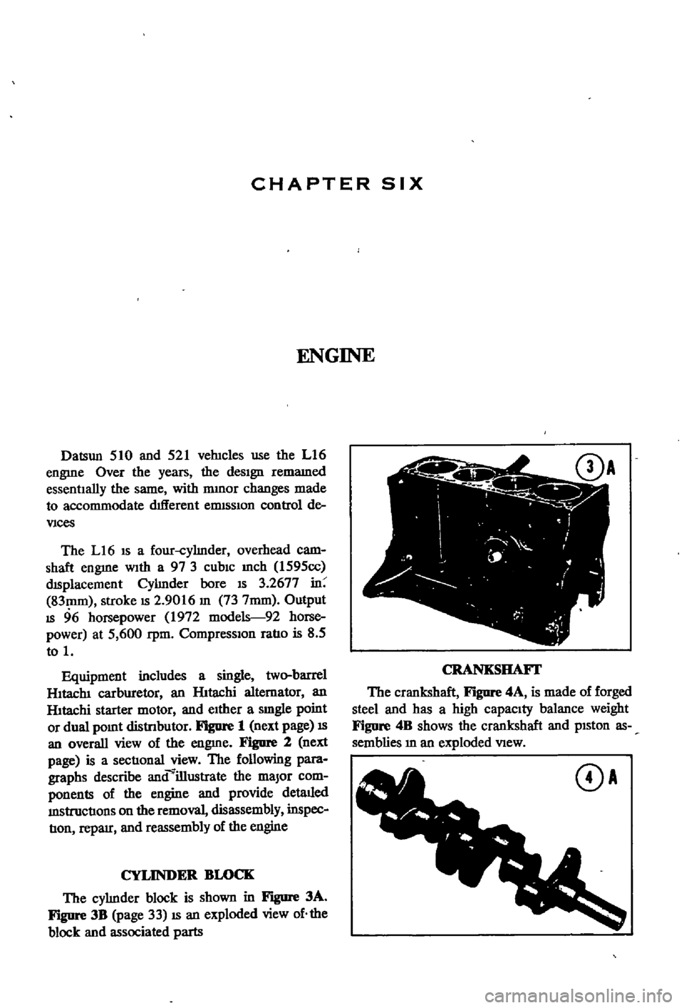
Datsun
510
and
521
veJucles
use
the
L16
engme
Over
the
years
the
deSign
remamed
essentIally
the
same
with
nunor
changes
made
to
accommodate
drlIerent
elIDSSlon
control
de
VIces
The
Ll6
IS
a
four
cylmder
overhead
cam
shaft
engme
With
a
97
3
cubic
mch
1595cc
dISplacement
Cylmder
bore
IS
3
2677
in
83mm
stroke
IS
2
9016
m
73
7mm
Output
IS
96
horsepower
1972
mode1s
92
horse
power
at
5
600
rpm
Compression
ratIo
is
8
5
to
1
Equipment
includes
a
single
two
barrel
Hltaclu
carburetor
an
HItachi
alternator
an
HItachi
starter
motor
and
either
a
smgle
point
or
dual
pomt
distnbutor
Figure
1
next
page
IS
an
overall
view
of
the
engme
Figure
2
next
page
is
a
sectIonal
view
The
following
para
graphs
describe
and
illustrate
the
major
com
ponents
of
the
engine
and
provide
detaIled
InStructIons
on
the
removal
disassembly
inspec
tIon
reparr
and
reassembly
of
the
engine
CYLINDER
BLOCK
The
cylmder
block
is
shown
in
Figure
3A
Figure
3B
page
33
IS
an
exploded
view
of
the
block
and
associated
parts
CRANKSHAFI
The
crankshaft
F
JgUre
4A
is
made
of
forged
steel
and
has
a
high
capacity
balance
weight
Figure
4B
shows
the
crankshaft
and
pISton
as
semblies
m
an
exploded
VIew
DA
Page 65 of 252

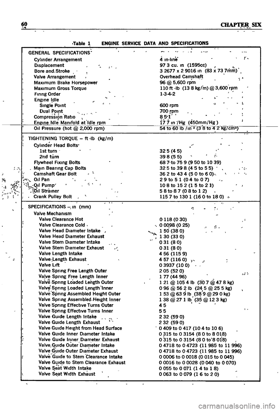
60
SIX
Table
1
ENGINE
SERVICE
DATA
AND
SPECIFICATIONS
GENERAL
SPECIFICATIONS
Cylinder
Arrangement
DIsplacement
Bore
and
Stroke
Valve
Arrangement
MaxImum
Brake
Horsepower
MaxImum
Gross
Torque
Firing
Order
Engme
dle
Smgle
POint
Dual
Pomt
CompressIon
RatIo
Engme
Idle
Mamfold
at
Idle
rpm
011
Pressure
hot
@
2
000
rpm
i
TIGHTENING
TORQUE
ft
Ib
kg
m
Cylinder
Head
Bolts
1st
turn
2nd
turn
Flywheel
Flxmg
Bolts
M
In
Beanng
Cap
Bolts
Camshaft
Gear
Bolt
I
011
Pan
1
1
fF
I
011
Pump
QII
Stramer
F
I
Crank
Pulley
Bolt
SPECIFICATIONS
In
mm
Valve
Mechamsm
Valve
Clearance
Hot
Valve
Clearance
Cold
Valve
Head
DIameter
Intake
Valve
Head
DIameter
Exhaust
Valve
Stem
DIameter
Intake
Valve
Stem
DIameter
Exhaust
Valve
Length
Intake
Valve
Length
Exhaust
Valve
LIft
Valve
Spring
Free
Length
Outer
Valve
Sprmg
Free
Length
Inner
Vaiv
Spnng
Loaded
Length
Outer
Valve
Spring
Loaded
Length
Inner
Valve
Sprmg
Assembllld
HeIght
Outer
Valve
Spnng
Assembled
Helght
Inner
Valve
Spnng
Effective
Turns
Outer
Valve
Sprmg
EffectIve
Turns
Inner
Valve
GUIde
Length
Intake
Valve
GUIde
Length
Exhaust
Valve
GUIde
HeIght
from
Head
Surface
Valve
GUIde
Inner
DIameter
Intake
Valve
GUIde
Inner
DIameter
Exhaust
Va
Ive
GUIde
Outer
Dlam
eter
Intake
Valve
GUIde
Outer
DIameter
Exhaust
Valve
GUIde
to
Stem
Clearance
Intake
Valve
GUIde
to
Stem
Clearance
Exhaust
Valve
eat
W
dth
Intake
Valve
SEtat
WIdth
Exhaust
4
m
Ilnil
97
3
cu
m
1595cc
3
2677
x
2
9016
In
83
x
73
7mm
Overhead
Camshaft
96
@
5
600
rpm
110
ft
Ib
13
8
kg
m
@
3
600
rpm
1
3
4
2
r
600
rpm
700
pm
85
1
i7
7
In
Hg
450mm
Hg
54
to
60
Ib
m
2
3
8
tQ
4
2
Iig
cm
325
4
5
39
8
5
5
68
No
75
9
9
50
to
1039
325
to
39
8
4
5
to
5
5
362
to
43
4
50
to
60
2
9
to
5
1
0
4
to
0
7
108
to
15
2
1
5
to
2
1
58t087
08to
12
1157
to
130
1
160
to
180
o
118
0
30
o
0C
98
0
25
1
50
38
0
1
30
33
0
031
80
031
80
456
1159
4
57
116
O
03937
100
2
05
52
0
1
77
44
96
1
21
@
1054
Ib
3
07
@
47
8
kg
o
96
@
56
Ib
24
5
@
25
5
kg
1
53
@
63
9
Ib
38
9
@
29
0
kg
1
38
@
27
1
Ib
35
@
123
kg
45
I
55
2
32
59
0
2
32
59
0
0409
to
0
417
104
to
106
0315
to
03154
80
to
8018
0315
to
03154
80
to
8
Oi8
04718
to
04723
11
985
to
11
996
04718
to
04723
11
985
to
11
996
00006
to
00018
0
015
to
0
045
00016
to
00028
0040
to
0070
o
055
to
0
071
1
4
to
1
8
0063
to
0079
1
6
to
20
Page 243 of 252

INDEX
237
2
7
30
28
WIrIng
diagrams
WIrIng
harnesses
Electncal
system
engme
Alternator
Chargmg
ClfCUlt
Dlstnbutor
IgmtlOn
coIl
Spark
plugs
Starter
Voltage
regulator
Emission
control
crankcase
DescnptIon
General
mspectIon
SchematIc
vIew
VentIlatIOn
control
valve
EmIssIOn
control
exhaust
AIr
pump
AntI
backfire
valve
Check
valve
DescnptlOn
Engme
modificatIons
system
Exploded
and
schematIc
vIews
Mamtenance
and
testIng
Troubleshootmg
Emission
control
system
evaporatIve
Engme
Camshaft
and
beanngs
Camshaft
sprocket
Component
descnptIons
Componenl
reassembly
and
mstallatIon
CompressIOn
testmg
Connectmg
rod
beanngs
Connectmg
rods
Crankshaft
Crankshaft
and
tImmg
cham
Crankshafl
sprocket
Cylmder
block
CylInder
head
DescnptlOn
Disassembly
Exploded
view
Flywheel
InstallatIOn
LubncatIon
MaIO
bearmgs
PIston
nngs
Pistons
and
connectmg
rods
PiStOns
and
piston
pms
Reassembly
Removal
SectIonal
views
ServIce
data
SpeCificatIons
Troubleshootmg
Valve
rocker
PIvot
Valves
Engme
lubncatlon
DescnptIon
217
222
205
207
98
104
98
105
111
111
112
113
9197
104
122
122
121
38
114
123
115
120
114
15
123
48
54
53
31
38
5759
24
52
51
54
51
57
53
49
55
46
56
31
40
33
53
59
27
30
52
50
45
50
54
53
38
32
60
61
60
61
13
54
47
53
114
114
121
114
LubncatlOn
ClfCUlt
011
filter
011
pump
Engme
tune
up
Checks
miscellaneous
Compression
testIng
DIstributor
Dwell
angle
EqUIpment
usage
ReqUIred
eqUIpment
Spark
plugs
Tlmmg
Tlmmg
dual
pomt
dlstnbutor
Valve
clearances
Exhaust
systems
Exploded
views
InspectIon
InstallatIOn
Removal
pickup
Removal
sedan
and
wagon
F
Fan
clutch
DIsassembly
and
reassembly
OperatIon
and
mspectlon
Flywheel
Fuel
pump
Capacity
test
DescnptlOn
Exploded
views
InspectIOn
InstallatIOn
Reassembly
Removal
an
assembly
StatIc
pressure
test
Fuel
stramer
Fuel
system
Air
cleaner
Carburetor
Fuel
pump
Fuel
stramer
Fuel
tank
Troubleshootmg
Fuel
tank
DescnptIon
Exploded
Views
InspectIOn
and
repaIr
Installation
Removal
sedan
Removal
pick
up
Removal
wagon
Fuses
G
27
General
mformatIon
25
24
21
24
20
20
21
23
24
25
124
126
126
126
126
123
l
89
89
53
68
37
65
66
67
68
58
68
42
68
65
1
2v
62
69
65
68
l
6
7
1
l
76
78
81
82
82
76
82
7
6
2
1
F