Page 138 of 252

CLUTCH
TRANSMISSION
AND
DRlVESIIAFI
133
C
8
Q@J
@
C
Operating
Cylinder
Reassembly
1
Soak
pISton
cup
m
brake
flUid
and
Install
It
In
the
same
pOSitIOn
as
before
removal
2
Apply
brake
flUid
to
the
cylInder
and
pIston
before
mstalImg
piston
3
Replace
all
parts
m
the
reverse
order
of
removal
Operating
Cylinder
Installation
1
RemstallatIon
IS
the
reverse
of
removal
2
Bleed
aIr
from
the
hydraulIc
system
3
Adjust
the
pushrod
so
that
withdrawal
lever
end
play
IS
0
0787
to
0
1181
In
2
0
to
3
Omm
Procedures
for
the
adjustment
are
given
below
WITHDRAWAL
LEVER
AD
JUSTMENT
Correct
adjustment
of
the
clutch
withdrawal
lever
IS
essentIal
InsufficIent
free
travel
between
the
release
bearmg
and
dIaphragm
fingers
can
cause
the
clutch
to
slIp
ExceSSIve
free
travel
can
prevent
full
dISengagement
of
the
clutch
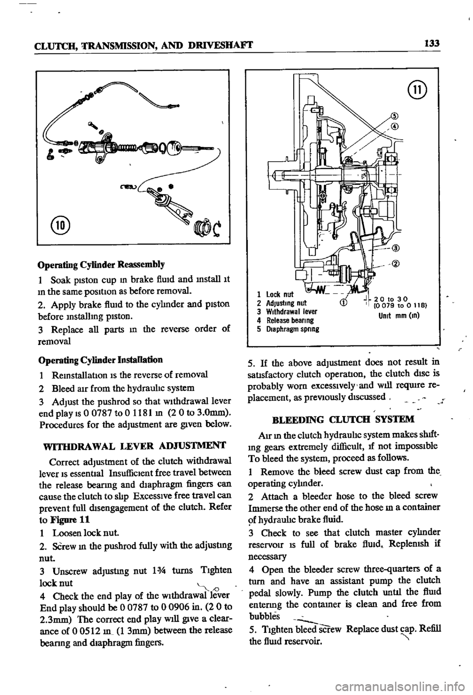
Refer
to
Figure
11
1
Loosen
lock
nut
2
SCrew
In
the
pushrod
fully
with
the
adjustmg
nut
3
Unscrew
adJustmg
nut
1
turns
TIghten
lock
nut
J
4
Check
the
end
play
of
the
wIthdrawal
lever
End
play
should
be
0
0787
to
0
0906
in
2
0
to
2
3mm
The
correct
end
play
will
give
a
clear
ance
of
0
0512
m
1
3mm
between
the
release
bearmg
and
diaphragm
fingers
@
1
Lock
nut
2
AdJustmg
nut
3
Wrthdrawal
ever
4
Release
beer
ng
5
Diaphragm
spnng
20
to
30
0
079
to
0
11
B
Unit
mm
m
5
If
the
above
adjustment
does
not
result
in
satIsfactory
clutch
operatIon
the
clutch
dISC
is
probably
worn
excessIvely
and
will
reqUire
re
placement
as
preVIously
dIScussed
BLEEDING
CLUTCH
SYSTEM
AIr
In
the
clutch
hydraulIc
system
makes
shIft
Ing
gears
extremely
difficult
1f
not
impOSSIble
To
bleed
the
system
proceed
as
follows
1
Remove
the
bleed
screw
dust
cap
from
the
operating
cylInder
2
Attach
a
bleeder
hose
to
the
bleed
screw
Immerse
the
other
end
of
the
hose
m
a
container
f
hydraulIc
brake
fluid
3
Check
to
see
that
clutch
master
cylInder
reservoir
IS
full
of
brake
flUid
ReplenISh
if
necessary
4
Open
the
bleeder
screw
three
quarters
of
a
tlIrn
and
have
an
assistant
pump
the
clutch
pedal
slowly
Pump
the
clutch
until
the
flUid
entenng
the
contatner
is
clean
and
free
from
bubbles
5
TIghten
bleed
screw
Replace
dust
cap
Refill
the
flUid
reservoir
Page 201 of 252

196
CHAPTER
FOURTEEN
WHEEL
CYLINDERS
pICK
UP
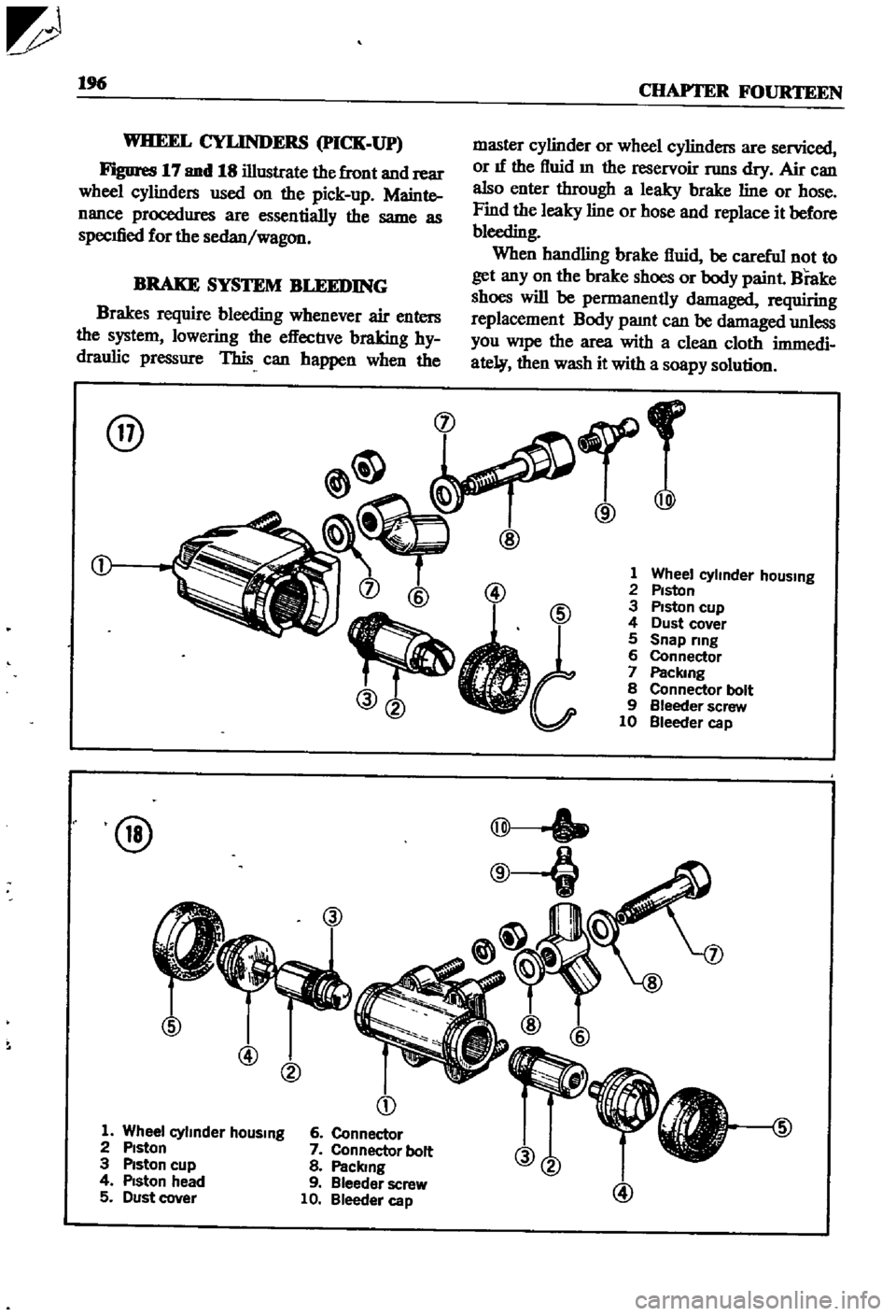
Figures
17
and
18
illustrate
the
front
and
rear
wheel
cylinders
used
on
the
pick
up
Mainte
nance
procedures
are
essentially
the
same
as
specIfied
for
the
sedan
wagon
BRAKE
SYSTEM
BLEEDING
Brakes
require
bleeding
whenever
air
enters
the
system
lowering
the
effectIve
braking
hy
draulic
pressure
This
can
happen
when
the
@
@
@
@
D
1
Wheel
cylmder
hOUSing
2
Piston
3
Piston
cup
4
Piston
head
5
Dust
cover
6
Connector
7
Connector
bolt
8
Paclang
9
Bleeder
screw
10
Bleeder
cap
master
cylinder
or
wheel
cylinders
are
serviced
or
If
the
fluid
m
the
reservoir
TWlS
dry
Air
can
also
enter
through
a
leaky
brake
line
or
hose
Find
the
leaky
line
or
hose
and
replace
it
before
bleeding
When
handling
brake
fluid
be
careful
not
to
get
any
on
the
brake
shoes
or
body
paint
Brake
shoes
will
be
permanently
damaged
requiring
replacement
Body
pamt
can
be
damaged
unless
you
Wipe
the
area
with
a
clean
cloth
immedi
ate
then
wash
it
with
a
soapy
solution
r
@
@
1
Wheel
cyhnder
hOUSing
2
Piston
3
Piston
cup
4
Dust
cover
5
Snap
ring
6
Connector
7
Packmg
8
Connector
bolt
9
Bleeder
screw
10
Bleeder
cap
@
Page 241 of 252

INDEX
A
Inspection
and
repair
191
Air
cleaner
Pad
replacement
190
Exploded
views
63
64
Piston
seal
replacement
193
Removal
and
replacement
62
Reassembly
and
installation
193
Removal
190
Air
pump
40
Brakes
front
pick
up
Alternator
Brushes
104
Adjustment
201
Diode
103
Exploded
View
195
Disassembly
98
ServiCing
194
SpecdicatIons
194
203
204
Exploded
Views
41
99
Brakes
rear
pick
up
Inspection
and
repair
101
Adjustment
202
Output
checks
104
Exploded
View
195
Reassembly
104
Servicing
194
Removal
40
98
Brakes
rear
sedan
and
wagon
Rotor
102
Adjustment
202
Stator
102
Exploded
view
194
Axle
removal
pick
up
175
Inspection
and
repair
193
Reassembly
194
B
Removal
and
disassembly
193
Breaker
points
110
Ball
JOint
lower
sedan
and
wagon
174
Bumpers
Battery
Exploded
view
front
pick
up
223
Inspecllon
aiii
I
servicing
21
Exploded
View
front
sedan
and
wagon
224
SpeCific
gravity
21
Exploded
view
rear
sedan
230
Body
Exploded
view
rear
wagon
231
Body
Irlm
and
bumpers
223
224
Door
lock
and
regulator
225
C
Doors
225
Hood
lock
control
225
Camshaft
Seats
228
DeSCription
34
Tail
gate
228
Exploded
view
37
Trunk
hd
and
bumper
228
Inspection
48
Brake
pedal
Reassembly
54
Inspection
and
repair
187
Sprocket
53
Installation
188
Tlmmg
chain
57
Removal
187
Carburetor
Brakes
Cleaning
and
inspection
75
Adjustment
201
202
Dash
pot
adjustment
71
Bleeding
196
DesCription
37
69
Brake
pedal
187
Disassembly
71
Front
diSC
sedan
and
wagon
190
193
Exploded
Views
74
75
Front
drum
pick
up
194
Fuel
level
adjustment
69
Handbrake
197
201
Idhng
adjustment
69
Master
cyhnder
188
Interlock
valve
70
Rear
pick
up
194
Reassembly
76
Rear
sedan
and
wagon
193
Removal
40
71
SpeCifications
and
service
data
203
204
Sectional
view
69
Troubleshooting
16
Throttle
valve
70
Wheel
cyhnders
pIck
up
196
Charging
system
Brakes
front
diSC
sedan
and
wagon
Troubleshooting
12
Adjustment
201
Choke
and
accelerator
Disassembly
191
Disassembly
and
installation
82
Exploded
view
192
Exploded
view
83