1968 DATSUN 510 automatic transmission
[x] Cancel search: automatic transmissionPage 4 of 252
II
CHAPTER
SIX
ENGINE
Cylmder
block
Crankshaft
PistOns
and
connectmg
rods
Cyhnder
head
Camshaft
Valve
mechamsm
Camshaft
dnve
Mamfolds
011
pump
Fuel
pump
Carburetor
Emission
control
devIces
Engme
removal
Engme
dISassembly
Pistons
and
connectmg
rods
Cyhnder
head
Engme
mspectIon
and
replllr
Engme
reassembly
Service
data
and
speCifications
CHAPTER
SEVEN
FUEL
SYSTEM
Air
cleaner
Fuel
strlllner
Fuel
pump
Carburetor
Fuel
tank
1
CHAPTER
EIGHT
COOLING
SYSTEM
DescnptIon
Water
pump
Fan
clutch
Thermostat
Radiator
CHAPTER
NINE
ENGINE
ELECTRICAL
SYSTEM
Starter
Overrunmng
clutch
assembly
ChargIng
ClrcUlt
Alternator
Alternator
output
Voltage
regulator
DIstrIbutor
Condenser
Igrntlon
cod
SpeCifications
Spark
plugs
CHAPTER
TEN
EMISSION
CONTROL
SYSTEM
Exhaust
emiSSIOn
control
Crankcase
emission
control
Air
mJectlon
system
Engme
modifications
Evaporative
emiSSion
control
Exhaust
system
CHAPTER
ELEVEN
CLUTCH
TRANSMISSION
AND
DRIVESHAFT
Clutch
TransmissIon
Master
cyhnder
TransmissIon
data
and
speCIfications
Operating
cyhnder
Dnveshaft
Withdrawal
lever
adjustment
Dnveshaft
data
and
speCIfications
Clutch
system
bleedmg
Automatic
transmIssIon
checks
Clutch
data
and
speCIfications
31
62
84
91
114
127
Page 6 of 252
CHAPTER
ONE
GENERAL
INFORMATION
This
manual
provides
maintenance
informa
tIon
on
the
Datsun
510
Series
and
521
Series
of
vehlcles
The
510
Series
includes
the
two
door
sedan
four
door
sedan
and
station
wagon
The
521
Senes
IS
the
pIck
up
truck
Coverage
is
from
1968
through
1972
models
All
models
use
the
L16
engme
a
96
horse
power
four
cylmder
overhead
camshaft
design
The
510
has
a
fully
synchronized
four
speed
manual
or
three
speed
automatic
transmisSIon
The
521
has
a
four
speed
manual
transmission
only
In
1972
horsepower
ratIng
was
lowered
to
92
horsepower
due
to
changes
m
emission
control
device
requirements
Figure
1
is
an
over
all
view
of
the
four
door
sedan
Figure
2
shows
the
station
wagon
and
Figure
3
illustrates
the
pick
up
truck
Over
the
years
the
510
and
521
series
have
remained
essentIally
the
same
with
the
excep
tion
of
changes
to
the
emISsion
control
systems
and
overall
body
stylmg
In
this
manual
every
effort
has
been
made
to
pinpoint
significant
c
if
ferences
between
model
years
The
use
of
SpecIal
tools
and
test
equipment
has
been
avoided
wherever
possible
When
necessary
special
tools
and
test
equipment
are
illustrated
either
in
actual
use
or
alone
A
well
equipped
mecharuc
may
find
he
can
substitute
similar
tools
or
make
his
own
to
fulfill
a
e
Ii
ment
Recommendations
are
occasionally
made
to
refer
servIce
or
mamtenance
to
a
Datsun
dealer
or
a
SpecIaliSt
in
a
specIfied
field
In
these
cases
work
WIll
probably
be
done
more
qUlckly
and
economIcally
than
if
the
mecharuc
performs
them
himself
MODEL
IDENTIFICATION
Body
Number
Plate
The
body
number
IS
stamped
on
the
fire
wall
in
the
engine
compartment
The
numbers
give
the
chasSIS
model
and
serial
number
Model
Identification
Plate
The
model
Identification
plate
Figure
4
is
mounted
WIthin
the
engine
compartment
TIns
plate
gIves
engine
number
and
veh1cle
number
Engine
Identification
The
engine
identrlicatlon
marking
is
stamped
on
the
right
hand
SIde
of
the
cylinder
block
just
below
the
third
and
fourth
sp8l
k
plugs
Model
Identification
Numbel
ll
The
following
numbers
have
been
assigned
to
the
510
and
52
I
Series
vehicles
oj
Page 9 of 252
4
CHAPTER
ONE
chassIs
number
Write
the
numbers
down
and
carry
them
ill
your
wallet
Service
Hints
Throughout
thIs
manual
keep
two
conven
bons
ill
mmd
Front
refers
to
the
front
of
the
vehicle
The
left
and
nght
sides
of
the
ve
hicle
refer
to
a
person
sittIng
ill
the
car
facing
forward
For
example
the
steenng
wheelIS
on
the
left
hand
Side
All
dimensIOns
and
capacities
are
expressed
ill
units
fanuhar
to
a
Umted
States
mechaniC
such
as
illches
and
pounds
Metric
measurements
are
also
given
Metnc
tools
are
reqUITed
to
work
on
the
Datsun
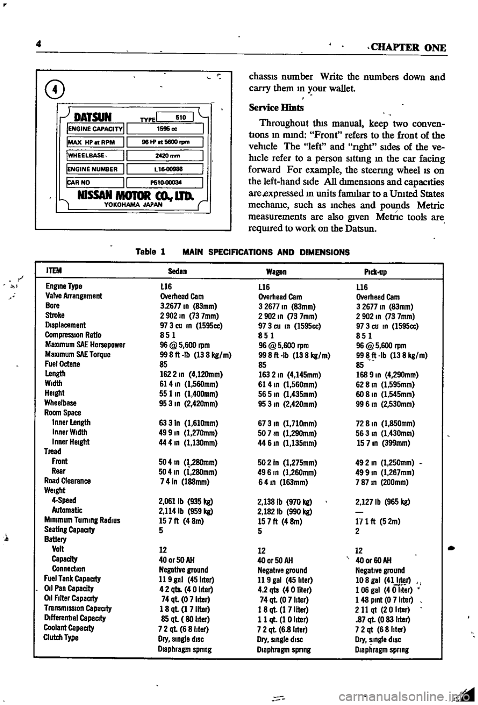
CD
DATSUN
IENGINE
CAPACITY
IMAX
HP
RPM
IWHEELBASE
IENGINE
NUMBER
FAR
NO
NlSSAN
MOTOR
co
LTD
YOKOHAMA
JAPAN
TYPEI
510
1595
cc
961P
6600
rpm
mm
L
1
00988
P61
l
O
1
l
M
Table
1
MAIN
SPECIFICATIONS
AND
DIMENSIONS
r
ITEM
Sedan
Wagon
Plm
up
EnglDe
Type
L16
L16
L16
Valve
Arrangement
Overhead
Cam
Overhead
Cam
Overhead
Cam
Bore
3
26n
ID
83mm
3
2677
ID
83mm
3
2677
ID
83mm
Stroke
2902
ID
73
7mm
2
902
ID
73
7mm
2
902
In
73
7mm
Displacement
97
3
cu
ID
l595cc
97
3
cu
In
l595cc
97
3
cu
ID
1595cc
CompressIOn
Ratio
851
851
851
MaXimum
SAE
Hompower
96
@
5
600
rpm
96
@
5
600
rpm
96
@
5
600
rpm
MaXimum
SAE
Torque
998ft
Ib
138
kg
m
998ft
Ib
138
kg
m
9911
ft
Ib
138
kg
m
Fuel
Octane
85
85
85
Lengtb
1622
ID
4
12Omm
163
2
ID
4
I45mm
168
9
ID
4
290mm
Width
61
4
ID
l
560mm
61
4
ID
1
560mm
62
8
In
Cl
595mm
Height
55
lID
1
400mm
565
ID
Cl
435mm
60
8
ID
Cl
545mm
Wheelbase
95
3
ID
2
42Omm
95
3
ID
2
420mm
99
6
In
2
530mm
Room
Space
Inner
Length
63
3
In
1
61Omm
673
ID
1
710mm
72
8
ID
1
850mm
Inner
Width
499
ID
1
27Omm
507
ID
1
29Omm
563
In
1
430mm
Inner
Height
44
4
In
1
130mm
44
61D
1
135mm
15
7
ID
399mm
Tread
Front
50
4
ID
28Omm
502
In
1
275mm
492
In
1
250mm
Rear
504
In
1
280mm
496
In
Cl
260mm
499
ID
1
267mm
Road
Clearance
741n
l88mm
64
ID
l63mm
787
ID
200mm
Weight
4
Speed
2
0611b
935
kg
2
138
Ib
970
kg
2
127
Ib
965
kg
Automatic
2
114Ib
959
kg
2
182
Ib
990
kg
Minimum
Turning
RadiUS
157ft
48m
157ft
48m
171
ft
52m
Seating
Capaaty
5
5
2
Battery
Volt
12
12
12
Capacity
400rSOAH
400r50AH
40
or
60
AH
Connection
Negative
ground
Negative
ground
Negative
ground
Fuel
Tank
Capaaty
11
9
gal
45
liter
11
9
gal
45
liter
108
gal
41J
r
011
Pan
Capacity
42
qts
40
liter
4
2
qb
40
liter
1
06
gal
40
Iller
011
Filter
Capaaty
74
ql
07
liter
74
ql
0
7
liter
1
48
Pint
0
7
liter
Transmission
Capaaty
1
8
ql
1
7
liter
18
ql
1
7
Iller
2
11
qt
20
Iller
Dlflerenbal
Capaaty
85
ql
80
liter
11
ql
1
0
liter
87
ql
0
83
lIter
Coolant
Capaaty
7
2
ql
6
8
liter
7
2
ql
6
8
lIter
7
2
qt
6
8
Iller
Clutch
Type
Dry
Single
diSC
Dry
slDgle
diSC
Dry
slDgle
diSC
Draphragm
spnng
Diaphragm
spnng
Diaphragm
spnng
l
Page 10 of 252
GENERAL
INFORMATION
5
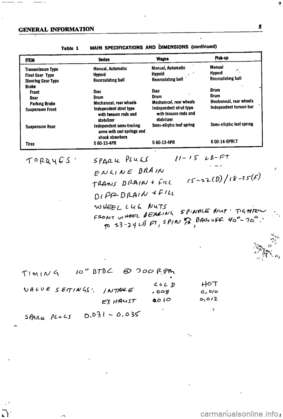
Table
1
MAIN
SPECIFICATIONS
AND
DIMENSIONS
continued
Suspension
Rear
Sedan
Wagon
Pick
up
Manual
Automatic
Manual
Automatic
Manual
HypoJd
Hypoid
Hypold
ReCIrculating
ball
ReCIrculating
ball
ReCirculating
ball
DIsc
DIsc
Drum
Drum
Drum
Drum
Mechanical
rear
wheels
Mechanical
rear
wheels
Mechanical
rear
wheels
Independent
strut
type
Independent
strut
type
Independent
torsion
bar
with
tension
rods
and
with
tension
rods
and
stabilizer
stabilIZer
Independent
semi
trailing
Semi
elliptiC
leaf
spring
Semi
elliptic
leaf
spnng
arms
wrtII
coli
springs
and
shock
absorbers
5
6O
13
4PR
5
6O
13
4PR
600
14
6PRLT
ITEM
Transmission
Type
Final
Gear
Type
Steering
Gear
Type
Brake
Front
Rear
Parking
Brake
Suspension
Front
Tires
6
2
Q
1
C
S
PA
l
PlLlU
EN
4
1
AJ
E
Dt7
A
1
1
1
2
A
ru
r
f
f
A
I
III
r
c
o
I
pP
D
LA
I
tV
r
IL
c
W
L
L
l
G
ftiv
TJ
dE
IJ
S
prlc
I
u
F
l
e
p
f
vi
Ii
ftl
1
3
l
1t
J
p7
5
PrlV
B4dc
u
11
1
S
t
f
PT
f
L
UJ
ff
zr
F
T
ff
lfo
1oo
4
t
M
0
IY
AJ
to
BTOL
@
OD
2
lP
S
PAtl
pI
c
5
IN
G
ex
Sf
0103
I
D
0
3
O
j
oo
0
0
0
to
l
c
o
0
0
2
JP
t
UE
SEIT
A
C
1
J
Page 29 of 252

P
r
OVll
t
ate
I
l
h
l
JlA
ye
I
o
ctg
fI
O
0
I
d
1e
d
c
Ji
uo
JJ
cb
c
s
rlr
I
l
4
c
1
2
24
CHAPTER
FOUR
block
and
should
be
used
as
the
reference
point
m
II
1akmg
adjustments
6
With
a
piece
of
white
chalk
mark
a
hne
down
the
center
of
the
pomter
and
mark
the
timing
groove
on
the
crankshaft
pulley
which
IS
to
be
used
m
tImmg
the
engine
SpecIficatIon
for
tun
ing
reqUIres
trlhmg
at
10
degrees
before
top
dead
center
wluch
would
be
the
fourth
mark
from
the
left
end
of
the
row
of
marks
7
Loosen
the
hold
down
bolt
at
the
base
of
the
dlstnbutor
8
Locate
the
slow
speed
1
Ile
adjustIng
screw
on
the
carburetor
so
that
Ile
speed
can
be
adjusted
whIle
runnmg
Also
locate
throttle
adJustmg
screw
9
Start
engme
and
adjust
speed
With
the
adJust
ing
screws
to
the
readmgs
below
Smgle
pomt
dIStributor
600
rpm
Dual
pomt
trlbutor
700
rpm
10
Alternate
adjustment
of
the
two
screws
untIl
the
smoothest
Idle
at
the
proper
speed
IS
achieved
11
Pomt
the
tlIrung
lIght
at
the
stationary
pomter
When
the
lIght
flashes
the
timmg
mark
n
the
crankshaft
pulley
should
hne
up
With
the
mark
on
the
stationary
pomter
If
It
does
not
exactly
Ime
up
rotate
the
dlstnbutor
gradually
untIl
the
marks
align
mdlcatlng
correct
timmg
12
Shut
off
the
engme
remove
the
tmung
lIght
and
tachometer
tighten
the
hold
down
bolt
on
the
dlStnbutor
and
connect
the
vacuum
advance
hne
to
the
tli
tnbutor
IGNITION
TIMING
IDLE
SPEED
IDLE
MIXTURE
DUAL
POINT
DISTRIBUTOR
ONLY
The
followmg
applies
to
velucles
With
dual
pomt
distributor
and
an
exhaust
emission
con
trol
deVice
If
these
procedures
are
followed
ha
ul
exhaust
emisSion
should
be
below
the
maximum
allowable
level
1
Locate
the
Idle
and
throttle
adJustmg
screws
on
the
carburetor
2
Warm
up
the
engine
thoroughly
3
Connect
tachometer
and
tmung
light
4
Set
the
Id
le
speed
at
700
rpm
With
the
Idle
adjust
screw
5
Adjust
IgnltJ
on
tuning
at
10
degrees
before
top
dead
center
6
Increase
the
speed
of
the
engme
to
2
000
rpm
With
the
accelerator
or
throttle
hnkage
and
hold
for
about
15
seconds
7
Return
to
Idle
for
one
mmute
8
Set
the
engme
to
best
Idle
at
750
rpm
770
rpm
for
automatJ
c
transIDlsslOn
With
the
Idle
and
throttle
adJustmg
screws
9
Re
uce
engme
speed
at
700
rpm
720
rpm
for
automatic
transmission
by
turnmg
the
Idle
adJustmg
screw
clockWise
for
a
leaner
IlliXture
10
Connect
a
wife
lead
between
the
advance
ami
retard
Side
tenrunals
See
Figure
4
Speed
should
drop
from
100
to
150
rpm
11
Check
IgIl1tIon
tmung
With
tImmg
light
It
should
now
be
at
top
d
ad
center
12
If
the
tlmmg
IS
nSJt
correct
stop
the
engme
and
adjust
the
retarded
breaker
pomt
13
Start
the
engme
and
reclieck
ili
tmung
If
l
incorrect
reset
the
retarded
breaker
pomt
until
it
IS
correct
Repeat
s
nece
s
14
Disconnect
the
wife
bet
reen
the
advance
and
retard
termmals
15
Recheck
tmung
It
should
be
10
degrees
before
top
dead
center
16
If
mcorrect
repeat
the
above
procedures
un
tIl
satIsfactory
17
T
he
Idle
speed
of
automatic
transnllsslOn
vehicles
should
be
about
575
rpm
With
the
gear
j
selector
m
the
dhve
poSltlon
c
t
DWELL
ANGLE
SETIING
1
Connect
the
dwell
angle
meter
2
PLoJust
dwell
angle
to
49
to
55
degrees
OMPRESSION
TEST
I
A
compressIOn
test
IS
performed
to
check
for
worn
piston
nngs
or
to
detect
the
cause
of
a
low
speed
miss
Before
undertaking
the
test
el
llmate
the
pOSSibility
of
sticky
valves
by
usmg
one
of
the
oil
additives
deSigned
for
the
purpose
With
valves
free
test
compressIOn
as
follows
1
Run
the
engme
for
15
to
20
mmutes
untIl
normal
operating
temperatures
are
obtained
2
Shut
off
engme
remove
arr
cleaner
and
Page 40 of 252
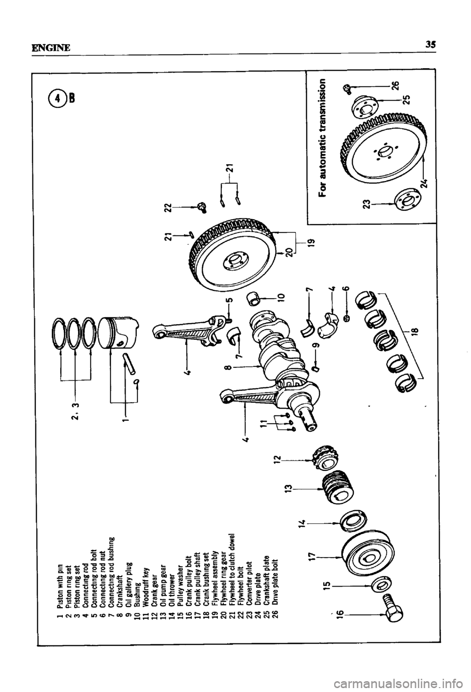
I
Piston
with
pin
2
Piston
nng
set
3
Piston
nng
set
4
Connecting
rod
5
Connecting
rod
bolt
6
Connecting
rod
nut
7
Connecting
rod
bushing
8
Crankshaft
9
011
gallery
plug
10
Bushing
11
Woodruff
key
12
Crank
gear
13
011
pump
gear
14
OJlthrower
15
Pulley
washer
16
Crank
pulley
bolt
17
Crank
pulley
shaft
18
Crank
bushing
set
19
Flywheel
assembly
20
Flywheel
nng
gear
21
Flywheel
to
clutch
dowel
22
Flywheel
bolt
4
23
Converter
pilot
24
Dnve
plate
25
Crankshaft
plate
26
Dnve
plate
bolt
13
I
14
17
15
2
3
l
L
4
8
9
6
19
1
J
21
2
24
8
ICD
I
For
automatic
transmission
W
lit
Page 42 of 252
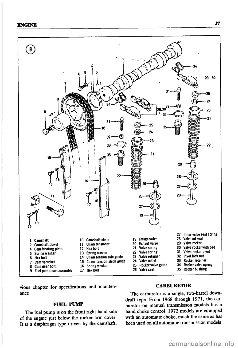
ENGINE
37
CD
4
11lL
8
311
@
2S
10
32
@
@
24
33
Q
23
1
21
rl
qp
12
26
27
19
34
30
31
1
25
@
24
W
32
@
30
33
0
21
28
tJ
2S
ctJ5J
27
20
II
27
Inner
valve
seat
spnng
1
Camshaft
10
Camshaft
cham
19
Intake
valve
28
Valve
011
seal
2
Camshaft
dowel
11
Chain
tensloner
20
Exhaut
valve
29
Valve
rocker
4
Cam
locating
plate
12
Hex
bolt
21
Valve
spnng
30
Valve
rocker
WIth
pad
5
Spnng
washer
13
Spnng
washer
22
Valve
spnng
31
Valve
rocker
Pivot
6
Hex
bolt
14
Chain
tension
Side
gUide
23
Valve
retamer
32
Pivot
ICICk
nul
7
Cam
sprocket
15
Chain
tension
slack
gUide
24
Valve
collet
33
Rocker
retainer
8
Cam
gear
bolt
16
Spnng
washer
25
Rocker
valve
guide
34
Rocker
valve
spnng
9
Fuel
pump
earn
assembly
17
Hex
bolt
26
Valve
seat
35
Rocker
bushing
vious
chapter
for
specmcaoons
and
mamten
ance
CARBURETOR
The
carburetor
IS
a
smgle
two
barrel
down
draft
type
From
1968
through
1971
the
car
buretor
on
manual
transmissIOn
models
has
a
hand
choke
control
1972
models
are
eqUIpped
With
an
automatic
choke
much
the
same
as
has
been
used
on
all
automaoc
transmISSion
models
FUEL
PUMP
The
fuel
pump
IS
on
the
front
right
hand
Side
of
the
engme
Just
below
the
rocker
arm
cover
It
IS
a
diaphragm
type
dnven
by
the
camshaft
Page 43 of 252
38
CHAPTER
SIX
EMISSION
CONTROL
DEVICES
All
Datsuns
have
a
sealed
type
of
crankcase
emISSion
control
device
and
an
exhaust
emISsion
control
deVice
Models
sold
m
Cahfornla
smce
1970
also
have
an
evaporative
emisSion
control
deVice
An
rmportant
part
of
the
exhaust
control
device
is
the
air
pump
located
at
the
bottom
left
hand
side
of
the
engme
It
IS
dnven
by
a
belt
off
of
the
crankshaft
pulley
and
supphes
air
to
the
exhaust
system
In
1972
an
electric
blower
in
corporated
m
the
air
cleaner
replaced
the
mechanical
pumI
ENGINE
REMOVAL
Expenence
has
shown
It
IS
easier
to
remove
the
engine
and
the
transmission
as
a
smgle
UnIt
than
to
remove
the
engme
alone
Once
the
en
gine
and
transmiSSIon
are
out
of
the
vehIcle
the
tranSmIssion
can
be
detached
from
the
engme
To
remove
the
engme
transmISsion
proceed
as
follows
1
Scribe
ahgnment
marks
on
the
hood
around
the
hmges
ThIS
will
make
remstallatlon
eaSIer
2
Remove
the
two
bolts
that
secure
each
hInge
and
remove
the
hood
It
is
not
necessary
to
re
move
the
hood
support
from
the
engme
firewall
3
DISconnect
the
lower
radIator
hose
from
the
right
hand
SIde
of
the
engine
and
at
the
bottom
of
the
radIator
ThIS
will
pernnt
coolant
to
dram
from
the
engme
and
the
radIator
4
Remove
the
draIn
plugs
from
the
engine
pan
and
translIDSsIon
and
completely
dram
lubn
cants
Into
suitable
contamers
5
DISconnect
the
battery
cables
from
the
bat
tery
loosen
the
two
hold
down
clamps
and
re
move
the
battery
NOTE
The
location
and
number
of
hoses
to
be
removed
from
the
air
cleaner
varies
from
model
to
model
It
IS
normally
easier
to
remove
the
hoses
from
the
sources
rather
than
try
to
dISconnect
them
from
yndemeath
the
air
cleaner
The
1972
model
Will
requlre
dlsconnectlOn
of
the
electrica1
cirCUit
In
the
air
cleaner
system
wing
nut
from
the
top
of
the
air
cleaner
and
remove
the
aIr
cleaner
7
DIsconnect
the
upper
radiator
hose
from
the
radiator
and
the
thermostat
housmg
Remove
the
hose
8
Disconnect
the
two
heater
hoses
from
the
nght
hand
side
of
the
engme
TIe
these
bac
so
they
won
t
interfere
with
removal
of
the
engme
9
Remove
the
radIator
grille
by
unscrewing
all
mountmg
screws
10
Remove
the
four
mounting
screws
holding
the
fan
shield
to
the
backside
of
the
radiator
11
Remove
the
four
mountmg
bolts
holdIng
the
radiator
In
place
In
automatic
tranSmISsion
models
dISconnect
the
two
transnnsslOn
oIl
cooler
lInes
from
the
bottom
of
the
radiator
Pull
the
radiator
straight
up
to
remove
Remove
the
fan
shield
12
Loosen
the
adjustment
and
mounting
bolts
from
the
retamIng
brackets
on
the
alternator
and
air
pump
If
so
eqwpped
The
alternator
is
lo
cated
at
the
bottom
nght
hand
Side
of
the
engme
and
the
air
pump
on
the
lower
left
hand
Side
13
Loosen
tenSIon
on
the
two
dnve
belts
re
move
the
belts
from
the
alternator
and
air
pump
and
then
from
the
fan
pulleys
14
Remove
the
bolts
holdIng
the
fan
and
pulley
to
the
water
pump
assembly
and
remove
the
fan
and
pulley
15
DISconnect
the
fuel
hne
from
the
fuel
pump
16
DIsco
ect
accelerator
control
linkage
and
choke
WIre
at
the
carburetor
17
Disconnect
the
wiring
from
the
starter
motor
alternator
Ignition
coIl
oIl
pressure
switch
and
temperature
transmItting
unit
NOTE
The
following
steps
are
per
formed
from
under
the
car
lack
up
the
front
of
the
car
and
position
stands
under
the
front
support
points
to
proVide
working
room
under
the
vehicle
WARNING
Never
climb
under
a
vehicle
that
is
supported
by
the
lack
only
If
stands
are
not
avflllable
sturdy
wooden
blocks
can
be
U3ed
6
Disconnect
all
hoses
that
lead
to
the
air
cleaner
remove
two
bolts
that
hold
the
air
cleaner
to
its
mountmg
bracket
unscrew
the
18
Remove
two
bolts
holdIng
the
clutch
operat
Ing
cylInder
to
the
flywheel
hOUSIng
shown
m