1968 DATSUN 510 automatic transmission
[x] Cancel search: automatic transmissionPage 48 of 252
ENGINE
43
@
0
00
o
mg
the
cham
tenslOner
to
the
block
to
free
the
sprIng
loaded
tenslOner
assembly
2
Remove
the
four
bolts
and
lockwashers
hold
mg
the
left
and
rIght
sIde
cham
guides
to
the
cylmder
block
Remove
the
guIdes
3
On
the
front
of
the
camshaft
remove
the
bolt
and
lockwasher
holdIng
the
fuel
pump
cam
as
sembly
and
the
eam
sprocket
to
the
eam
4
LIft
the
drIve
chaIn
asIde
and
remove
the
earn
sprocket
and
fuel
pump
cam
from
the
cam
shaft
as
shown
In
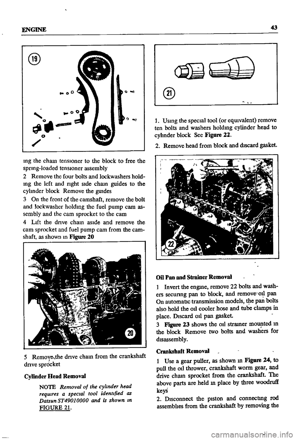
Figure
20
5
Remove
the
dnve
cham
from
the
crankshaft
drIve
spr6cket
Cylinder
Head
Removal
NOTE
Removal
of
the
cylinder
head
requires
a
special
tool
identified
as
DatsunST49010000
and
is
shown
In
FIGURE
21
@
I
USIng
the
specIal
tool
or
eqUIvalent
remove
ten
bolts
and
washers
holdIng
cylinder
head
to
cyhnder
block
See
Figure
22
2
Remove
head
from
block
and
dtscard
gasket
Oil
Pan
and
Strainer
Removal
I
Invert
the
engme
remove
22
bolts
and
wash
ers
secunng
pan
to
block
and
remove
011
pan
On
automatIc
transmission
models
tpe
pan
bolts
also
hold
the
oIl
cooler
hose
and
tube
clamps
in
place
DISCard
011
pan
gasket
3
Figure
23
shows
the
oIl
stramer
mOlJ
lted
m
the
block
Remove
two
bolts
and
washers
for
dISassembly
Crankshaft
Removal
I
Use
a
gear
puller
as
shown
III
Figure
24
to
pull
the
oIl
thrower
crankshaft
worm
gear
and
drive
cham
sprocket
from
the
crankshaft
The
above
parts
are
held
In
place
by
three
woodruff
keyS
2
DISconnect
the
pIston
and
connectrng
rod
assemblIes
from
the
crankshaft
by
removing
the
Page 74 of 252
FUEL
SYSTEM
69
CARBURETOR
The
carburetor
IS
an
Hltach1
Type
DAF328
Several
varIations
are
used
dependmg
on
the
model
year
type
of
transmissIOn
and
the
emIS
SIon
control
system
The
dIfferent
models
are
the
same
as
far
as
basiC
operation
IS
concerned
Therefore
the
followmg
dISCUSSIon
covers
a
typIcal
carburetor
The
automatIc
choke
IS
used
on
automatIc
transmISSIon
and
1972
models
only
All
other
chokes
are
manual
Refer
to
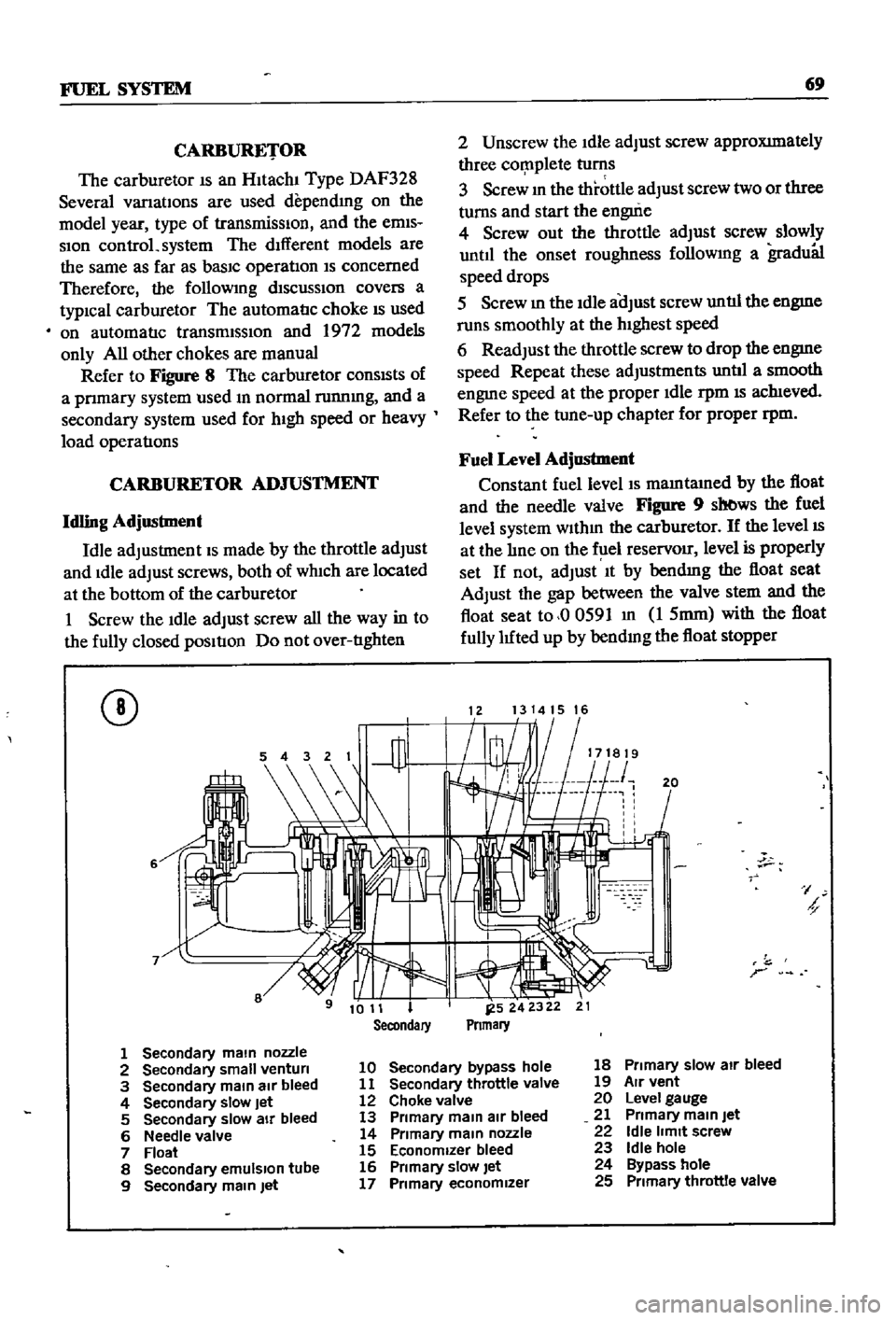
Figure
8
The
carburetor
conSIsts
of
a
pnmary
system
used
m
normal
runnmg
and
a
secondary
system
used
for
hIgh
speed
or
heavy
load
operatIons
CARBURETOR
ADJUSTMENT
Idling
Adjustment
Idle
adjustment
IS
made
by
the
throttle
adjust
and
Idle
adjust
screws
both
of
wh1ch
are
located
at
the
bottom
of
the
carburetor
1
Screw
the
Idle
adjust
screw
all
the
way
in
to
the
fully
closed
pOSItIon
Do
not
over
tIghten
CD
6
2
Unscrew
the
Idle
adjust
screw
approXImately
three
cor
nplete
turns
3
Screw
m
the
throttle
adjust
screw
two
or
three
turns
and
start
the
engui
e
4
Screw
out
the
throttle
adjust
screw
slowly
until
the
onset
roughness
followmg
a
gradu81
speed
drops
5
Screw
m
the
Idle
aOJust
screw
untIl
the
engme
runs
smoothly
at
the
hIghest
speed
6
Readjust
the
throttle
screw
to
drop
the
engme
speed
Repeat
these
adjustments
untIl
a
smooth
engme
speed
at
the
proper
Idle
rpm
IS
ach1eved
Refer
to
the
tune
up
chapter
for
proper
rpm
Fuel
Level
Adjustment
Constant
fuel
level
IS
mamtamed
by
the
float
and
the
needle
valve
Figure
9
sb
ws
the
fuel
level
system
wlthm
the
carburetor
If
the
level
IS
at
the
lIne
on
the
f
lel
reservOir
level
is
properly
set
If
not
adjust
It
by
bendmg
the
float
seat
Adjust
the
gap
between
the
valve
stem
and
the
float
seat
to
00591
m
1
5mm
with
the
float
fully
luted
up
by
bendmg
the
float
stopper
1213141516
20
I
h
r
1
Secondary
main
nozzle
2
Secondary
small
venturi
10
Secondary
bypass
hole
18
Primary
slow
air
bleed
3
Secondary
main
air
bleed
11
Secondary
throttle
valve
19
Air
vent
4
Secondary
slow
Jet
12
Choke
valve
20
Level
gauge
5
Secondary
slow
air
bleed
13
Primary
main
air
bleed
21
Primary
main
Jet
6
Needle
valve
14
Primary
main
nozzle
22
Idle
limit
screw
7
Float
15
Economizer
bleed
23
Idle
hole
8
Secondary
emulSion
tube
16
Primary
slow
let
24
Bypass
hole
9
Secondary
main
Jet
17
Primary
economizer
25
Primary
throttle
valve
Page 95 of 252
90
CHAPTER
EIGHT
degrees
C
The
maXImum
WIdth
of
the
thermo
stat
openIng
should
be
0315
In
8mm
3
If
the
thermostat
IS
defectIve
or
If
you
have
an
doubts
about
It
mstall
a
new
one
4
When
Installmg
the
thermostat
m
the
hous
Ing
be
certaIn
to
place
the
spnng
end
down
Coat
both
SIdes
of
the
gasket
WIth
sealer
to
pre
vent
leaks
and
tIghten
the
mountlng
nuts
securely
RADIATOR
The
radIator
IS
of
conventional
desIgn
A
draIn
cock
IS
proVIded
at
the
bottom
back
to
perrmt
drainIng
The
system
IS
pressurized
and
the
rehef
valve
incorporated
In
the
filler
cap
mamtains
the
pressure
at
approximately
12
8
Ib
in
0
9
kg
cm
Coolant
capacity
is
1
691
gallons
6
4
lIters
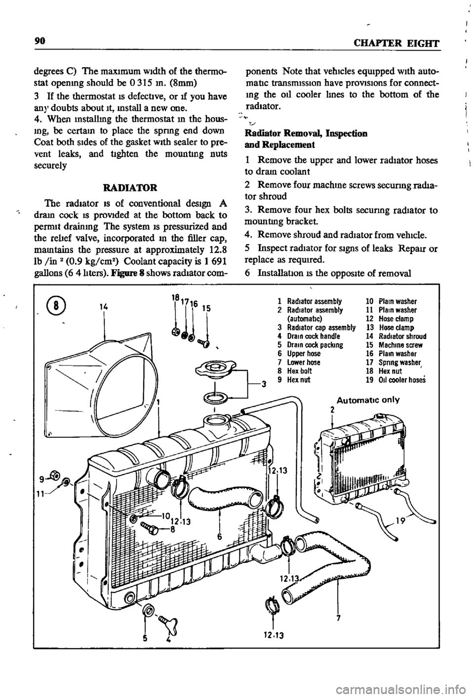
Figure
8
shows
radIator
com
ponents
Note
that
vehicles
equIpped
WIth
auto
matIc
transmISSIon
have
provlSlons
for
connect
Ing
the
011
cooler
lInes
to
the
bottom
of
the
radiator
Radiator
Removal
Inspection
and
Replacement
1
Remove
the
upper
and
lower
radIator
hoses
to
draIn
coolant
2
Remove
four
machme
screws
securmg
radIa
tor
shroud
3
Remove
four
hex
bolts
secunng
rad1ator
to
mountlng
bracket
4
Remove
shroud
and
radIator
from
vehIcle
5
Inspect
radIator
for
SignS
of
leaks
RepaIr
or
replace
as
required
6
InstallatIon
IS
the
OppOSIte
of
removal
CD
14
1
Radiator
assembly
10
Plain
washer
2
Radiator
assembly
11
Plain
washer
automal1c
12
Hose
clamp
3
RadIator
cap
assembly
13
Hose
clamp
4
Drain
cock
handle
14
Radiator
shroud
5
Drain
cock
packing
15
Machine
screw
6
Upper
hose
16
Plain
washer
7
Lower
hose
17
Spring
washer
8
Hex
bolt
18
Hex
nut
9
Hex
nut
19
011
cooler
hoses
Automatic
only
2
i
7
1213
Page 124 of 252
EMISSION
CONTROL
S
IS
TEM
SEDAN
AND
SlATION
YfAGON
Yfl
tH
AUTOMATIC
TRANSMISSION
TO
DISTRIBUTOR
IGNITION
COIL
IGNITION
SWITCH
tnE
RETARDED
BREAKER
POINT
1
SPEED
SWITCH
THROTTLE
SWITCH
SWITCH
DETECTING
WIDE
OPEN
THROTTLE
POSITION
SWITCH
DETECTING
CLOSE
THROTTLE
POS
iION
Q
Z
S
e
l
Page 139 of 252
134
CHAPTER
ELEVEN
CLUTCH
SERVICE
DATA
AND
SPECIF1CATIONS
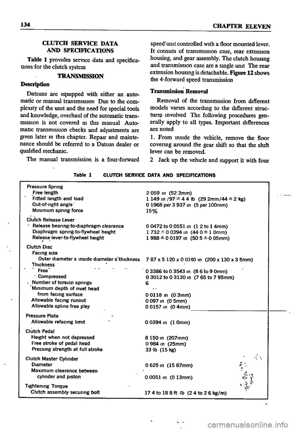
Table
1
proVIdes
serVIce
data
and
specifica
tIons
for
the
clutch
system
TRANSMISSION
Description
Datsuns
are
eqUIpped
with
either
an
auto
matic
or
manual
transrmSSIOn
Due
to
the
com
pleXity
of
the
unIt
and
the
need
for
special
tools
and
knowledge
overhaul
of
the
automatic
trans
mISSIon
is
not
covered
In
thIS
manual
Auto
matIc
transmISSIOn
checks
and
adjustments
are
given
later
m
thIS
chapter
Reparr
and
mainte
nance
should
be
referred
to
a
Datsun
dealer
or
qualIfied
mechamc
The
manual
transmission
is
a
four
forward
Table
1
speed
unlt
controlled
With
a
floor
mounted
lever
It
consIsts
of
transrmSSIOn
case
rear
extensIOn
housing
and
gear
assembly
The
clutch
housmg
and
transmissIOn
case
are
a
sIngle
unIt
The
rear
extension
housmg
is
detachable
Figure
12
shows
the
4
forward
speed
transmission
Transmission
Removal
Removal
of
the
transmIssion
from
dIfferent
models
Varles
accordmg
to
the
dIfferent
struc
ture
Involved
The
following
procedures
gen
erally
apply
to
all
types
Important
dIfferences
are
noted
1
Prom
InsIde
the
vehicle
remove
the
floor
covenng
around
the
gear
shift
so
that
the
shIft
lever
can
be
removed
2
Jack
up
the
vehIcle
and
support
it
with
four
CLUTCH
SERVICE
DATA
AND
SPECIFICATIONS
Pressure
Spring
Free
length
Fitted
length
and
load
Out
of
rlght
angle
MInimum
sprmg
force
Clutch
Release
Lever
Release
bearlng
to
dlaphragm
clearance
Diaphragm
sprlng
to
flywheel
height
Release
lever
to
flywheel
height
Clutch
DISC
FaCing
size
Outer
dIameter
x
inSide
diameter
x
thlckness
Thickness
Free
Compressed
Number
of
tOrslO
1
springs
Minimum
depth
of
rivet
head
from
faCing
surface
Allowable
facmg
runout
Allowable
spline
free
play
Pressure
Plate
Allowable
refacmg
limit
Clutch
Pedal
Height
when
not
depressed
Free
stroke
of
pedal
head
Pressmg
strength
at
full
stroke
Clutch
Master
Cylinder
Diameter
MaXimum
clearance
between
cylinder
and
pIston
Tightening
Torque
Clutch
assembly
securing
bolt
2
059
In
52
3mm
1
149
In
197
4
4
Ib
29
2mm
44
2
kg
o
1968
per
3
937
In
5
per
100mm
15
00472
to
0
0551
In
1
2
to
1
4mm
1732
0
0394
m
44
O
1
Omm
1
988
0
0197
In
505
0
05mm
787
X
5
120
x
0
0140
In
200
x
130
x
3
5mm
o
3386
to
0
3543
m
8
6
to
9
Omm
03012
to
0
3130
m
765
to
7
95mm
6
00118
In
03mm
o
097
In
0
5mm
00157
m
04mm
o
0394
In
1
Omm
8
150
m
207mm
o
984
m
25mm
33
Ib
15
kg
0625
m
15
87mm
00051
m
0
13mm
J
i
r
174
to
188ft
Ib
24
to
2
6
kg
m
Page 152 of 252
CLUTCH
TRANSMISSION
AND
DRIVESHAFI
147
SERVICE
DATA
AND
SPECIFICATIONS
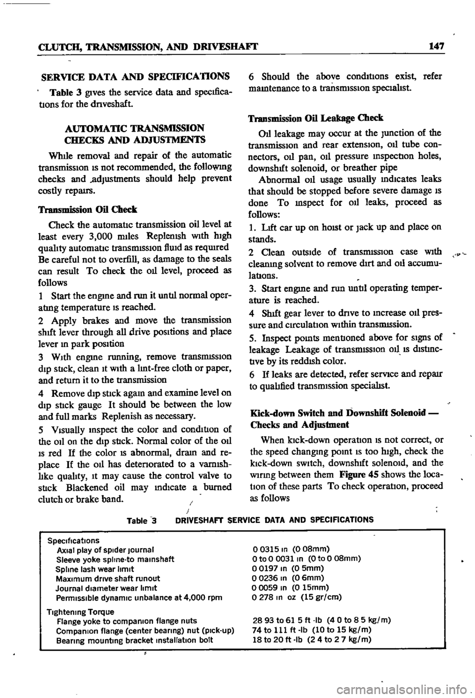
Table
3
gives
the
service
data
and
specIfica
tIons
for
the
dnveshaft
AUTOMATIC
TRANSMISSION
CHECKS
AND
ADJUSTMENTS
Whlle
removal
and
repair
of
the
automatic
transmisSIOn
IS
not
recommended
the
follo
VlIlg
checks
and
adjustments
should
help
prevent
costly
repatrs
Transmission
Oil
Check
Check
the
automatIc
transmission
oil
level
at
least
every
3
000
mlles
Replemsh
With
hIgh
qualIty
automatIc
transmISSIon
flUId
as
reqUIred
Be
careful
not
to
overfill
as
damage
to
the
seals
can
result
To
check
the
011
level
proceed
as
follows
1
Start
the
engme
and
nm
it
untIl
normal
oper
atrng
temperature
IS
reached
2
Apply
brakes
and
move
the
transmission
shut
lever
through
all
drive
pOSItions
and
place
lever
In
park
position
3
WIth
engme
running
remove
tranSmISSIon
dIp
StIck
clean
It
WIth
a
lInt
free
cloth
or
paper
and
return
it
to
the
transmission
4
Remove
dIp
stIck
agam
and
examine
level
on
dIp
stIck
gauge
It
should
be
between
the
low
and
full
marks
Replenish
as
necessary
5
VIsually
InSpect
the
color
and
condItIon
of
the
OIl
on
the
dIp
stIck
Normal
color
of
the
OIl
IS
red
If
the
color
IS
abnormal
dram
and
re
place
If
the
011
has
detenorated
to
a
vamlsh
lIke
qualIty
It
may
cause
the
control
valve
to
stIck
Blackened
oil
may
mdlcate
a
burned
clutch
or
brake
band
6
Should
the
above
condItIons
exist
refer
mamtenance
to
a
transmISSIon
specIalIst
Transmission
Oil
Leakage
Check
011
leakage
may
occur
at
the
Junction
of
the
transmissIon
and
rear
extensIon
011
tube
con
nectors
011
pan
OIl
pressure
mspectIon
holes
downshIft
solenoid
or
breather
pipe
Abnormal
OIl
usage
usually
mdlcates
leaks
that
should
be
stopped
before
severe
damage
IS
done
To
mspect
for
011
leaks
proceed
as
follows
1
LIft
car
up
on
hOISt
or
Jack
up
and
place
on
stands
2
Clean
outsIde
of
transmISSIon
case
With
cleanIng
solvent
to
remove
dIrt
and
011
accumu
latIons
3
Start
engme
and
nm
untIl
operating
temper
ature
is
reached
4
ShIft
gear
lever
to
dnve
to
Increase
011
pres
sure
and
CIrculatIon
WIthin
tranSmISsion
5
Inspect
pOInts
mentIoned
above
for
SIgnS
of
leakage
Leakage
of
transrmSSIOn
011
IS
dIStrnC
tIve
by
its
reddISh
color
6
If
leaks
are
detected
refer
servIce
and
reparr
to
qualIfied
transrmssion
specialISt
Kick
down
Switch
and
Downshift
Solenoid
Checks
and
Adjustment
When
ktck
down
operatIon
IS
not
correct
or
the
speed
changmg
pomt
IS
too
high
check
the
klck
down
SWItch
downshIft
solenOId
and
the
wlDng
between
them
Figure
45
shows
the
loca
tIOn
of
these
parts
To
check
operatIon
proceed
as
follows
Table
3
J
DRIVESHAFT
SERVICE
DATA
AND
SPECIFICATIONS
SpeCifications
Axial
play
of
spider
Journal
Sleeve
yoke
spltne
to
malnshaft
Spline
lash
wear
Itmlt
MaXimum
drive
shaft
runout
Journal
diameter
wear
limit
Penmlsslble
dynamiC
unbalance
at
4
000
rpm
Tightening
Torque
Flange
yoke
to
compaRlon
flange
nuts
CompaRlon
flange
center
bearing
nut
pick
up
Bearing
mounting
bracket
installation
bolt
00315
In
008mm
OtoO
0031
In
OtoO
08mm
00197
In
0
5mm
00236
In
06mm
00059
In
0
15mm
0278
In
oz
15
gr
cm
2893
to
615ft
Ib
40
to
8
5
kg
m
74
to
111
ft
Ib
10
to
15
kg
m
18
to
20
ft
Ib
24
to
2
7
kg
m
Page 222 of 252

BODY
ELECTRICAL
SYSTEM
217
bulb
socket
must
be
pulled
out
from
the
back
of
the
unit
and
then
the
bulb
can
be
replaced
Care
fully
mspect
the
unit
that
reqUIres
bulb
replace
ment
and
follow
the
appropriate
procedure
Make
certain
you
replace
the
bulb
with
one
rated
at
the
same
voltage
amperage
and
watt
age
Examples
of
units
that
might
require
bulb
replacement
are
the
front
park
and
directional
lamps
rear
combination
lamp
side
marker
lamps
interior
room
lamps
license
plate
lamps
and
engine
compartment
lamps
Fuse
Replacement
Whenever
a
fallure
occurs
m
any
part
of
the
electrical
system
always
check
the
fuse
box
to
see
1f
a
fuse
has
blown
The
fuse
box
is
located
on
the
firewall
within
the
engine
compartment
If
a
fuse
has
blown
It
will
be
eVident
by
bIacken
mg
of
the
fuse
or
by
a
break
of
the
metal
element
Within
the
fuse
The
wiring
diagrams
below
mdIcate
the
cir
cuits
that
are
connected
to
each
fuse
Before
replacing
a
fuse
always
detenIlIDe
what
caused
it
to
blow
and
correct
the
trouble
Never
replace
a
fuse
With
one
of
a
higher
amperage
ratIng
than
originally
used
Never
use
tmfOll
or
other
ma
tenal
to
Jump
across
fuse
tenIlIDals
Failure
to
follow
these
basic
rules
could
result
in
fire
or
damage
to
major
components
WIRING
DIAGRAMS
The
following
figures
provide
wiring
diagrams
for
the
sedan
wagon
and
pick
up
Figure
20
page
220
applies
to
the
sedan
and
station
wagon
with
manual
transmission
Figure
21
page
221
covers
the
sedan
and
station
wagon
With
automatic
transmission
Figure
22
page
222
is
for
the
pick
up
I
Page 245 of 252
l
INDEX
239
Rear
suspensIOn
wagon
Removal
40
92
Servlcmg
161
Termmals
94
Tightening
torques
162
Test
diagnosIs
97
Testmg
96
Troubleshootmg
10
5
Steenng
also
see
Suspension
front
I
Exploded
views
182
185
L
Seats
SpecIfications
186
DescnptIon
228
Troubleshooting
16
Exploded
View
front
4
door
sedan
232
SuspensIOn
front
pick
up
Exploded
VIew
front
pick
up
228
Axle
removal
175
Service
hmts
4
Inspection
and
repair
179
Shock
absorbers
sedan
154
Installation
179
Shock
absorbers
wagon
162
Posture
adjustment
181
Spark
plugs
Removal
177
CondlllOn
chart
21
Wheel
abgnment
182
InspectIon
and
servlcmg
21
Wheel
bearmg
adjustment
177
Recommended
types
112
Suspension
front
sedan
and
wagon
SpecificatIOns
and
tables
Inspection
and
repair
176
Adjustment
and
wheel
alignment
175
InstallatIOn
177
Brake
service
data
203
204
Lower
ball
Jomt
174
Brakes
203
204
Spnng
and
strut
assembly
173
Camshaft
beanngs
48
Stabilizer
173
Caster
and
camber
sedan
and
wagon
175
TenSIOn
rod
173
Clutch
134
Transverse
bnk
174
Clutch
service
data
134
Wheel
beanngs
177
Connectmg
rod
beanng
underslzes
52
Wheel
hubs
and
bearmgs
168
173
Dlstnbutor
112
SWItches
Dnveshaft
147
DescnptIon
205
Dnveshaft
service
dala
147
Exploded
View
through
1969
208
Engme
60
61
Exploded
view
1970
1972
207
Engme
service
data
60
61
General
4
Mam
bearmg
underslzes
52
T
Piston
rmg
gap
50
Rear
suspenSIOn
pick
up
167
Tail
gate
228
233
Rear
suspensIOn
torques
wagon
162
TenSIOn
rod
sedan
and
wagon
173
Steermg
186
Thermostat
TransmiSSion
manual
144
DescnptIon
89
TransmiSSion
service
data
manual
144
Inspection
and
replacement
89
Valve
spnng
47
Removal
89
Sprmg
and
strut
assembly
sedan
and
wagon
173
Tires
Spnngs
sedan
154
Wear
analYSIS
17
Stabilizer
sedan
and
wagon
173
TransmiSSion
automatic
Starter
Downshift
solenOid
147
Armature
95
Inhlbllor
SWItch
148
Beanngs
96
Kick
down
SWitch
147
Brush
holder
96
Lmkage
mspectIon
and
adjustment
148
Brushes
and
lead
WIre
95
011
checks
147
Cleaning
mspectIon
and
repair
94
Oil
leakage
147
Construcllon
92
TransmiSSion
manual
Disassembly
92
DescnptIon
134
Exploded
View
93
Disassembly
138
Field
COIl
94
Exploded
view
138
Magnetic
SWItch
96
Gear
assembly
exploded
view
139
Magnetic
SWItch
assembly
test
97
Inspection
and
repair
141
Operation
91
Installation
143
Overrunnmg
clutch
96
Reassembly
and
adjustment
142
Reassembly
96
Removal
134