Page 128 of 252

EMISSION
CONTROL
SYSTEM
123
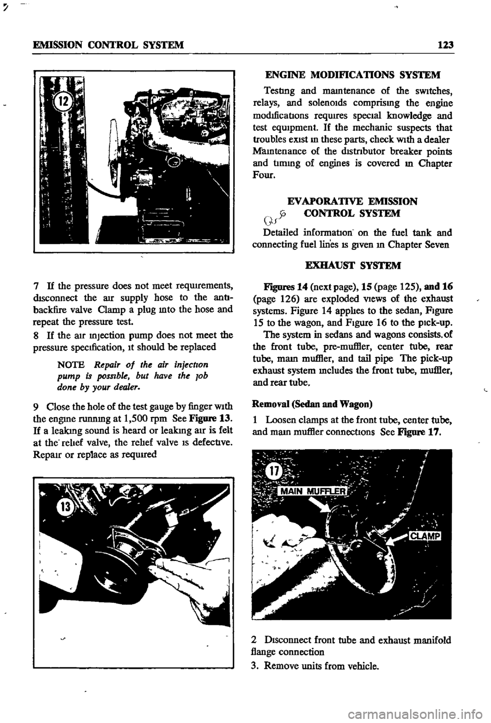
7
If
the
pressure
does
not
meet
reqwrements
dISconnect
the
aIr
supply
hose
to
the
antI
backfire
valve
Clamp
a
plug
mto
the
hose
and
repeat
the
pressure
test
8
If
the
air
mJection
pump
does
not
meet
the
pressure
specIfication
It
should
be
replaced
NOTE
Repair
of
the
air
injection
pump
is
possible
but
have
the
lob
done
by
your
dealer
9
Close
the
hole
of
the
test
gauge
by
finger
With
the
engme
runnmg
at
1
500
rpm
See
Figure
13
If
a
leakIng
sound
is
heard
or
leakIng
air
is
felt
at
the
relIef
valve
the
relIef
valve
IS
defectIve
RepaIr
or
replace
as
reqUIred
ENGINE
MODIFICATIONS
SYSTEM
Testlng
and
mamtenance
of
the
sWitches
relays
and
solenOIds
comprismg
the
engine
modIficatIons
reqwres
SpecIal
knowledge
and
test
eqUIpment
If
the
mechanic
suspects
that
troubles
eXist
In
these
parts
check
With
a
dealer
Mamtenance
of
the
dIstrIbutor
breaker
points
and
tImmg
of
engines
is
covered
m
Chapter
Four
EVAPORATIVE
EMISSION
y
CONTROL
SYSTEM
f
Detailed
informatIon
on
the
fuel
tank
and
connecting
fuel
lines
IS
given
In
Chapter
Seven
EXHAUST
SYSTEM
Figures
14
next
page
15
page
125
and
16
page
126
are
exploded
VIews
of
the
exhaust
systems
Figure
14
applIes
to
the
sedan
FIgure
15
to
the
wagon
and
FIgure
16
to
the
pIck
up
The
system
in
sedans
and
wagons
consists
of
the
front
tube
pre
muffier
center
tube
rear
tube
mam
muffier
and
tail
pipe
The
pick
up
exhaust
system
mcludes
the
front
tube
muffier
and
rear
tube
Removal
Sedan
and
Wagon
1
Loosen
clamps
at
the
front
tube
center
tube
and
mam
muffier
connectIons
See
Figure
17
2
DIsconnect
front
tube
and
exhaust
manifold
flange
connection
3
Remove
units
from
vehicle
Page 214 of 252
44
y
l
l
42
43
r
48
cr
23
41
f
Jj
it
d
F
1L
f7
IF
f
0
l
Q
U
lJ
37
1
2S
26
38
A
3S
36
G
21
Turn
signal
and
dimmer
switch
22
Turn
signal
switch
knob
23
Stop
light
switch
24
Door
switch
25
WarnIng
buzzer
26
Warning
buzzer
28
Fuse
block
29
Fuse
block
cover
30
Fuse
10
ampere
31
Fuse
20
ampere
32
Fuse
30
ampere
33
Machlnescrew
34
Lock
washer
35
Horn
hIgh
pitch
36
Horn
low
pitch
37
Machine
acrew
38
Lock
washer
39
Horn
relay
40
Lower
beem
relay
41
Inhibitor
switch
42
Screw
43
Flasher
unit
44
Screw
48
Bracket
o
i
Page 215 of 252

110
CHAPTER
FIFTEEN
FOR
MANUAL
IGNITION
KEY
i
I
MADV
Nf
D
BRAKE
POINT
v
sa
tS
57
51
Th
rottle
sWItch
52
Speed
sWItch
relay
53
Speed
detector
assembly
Q
FOR
AUTOMATIC
IGNITION
KEY
AOVANEO
BRAKE
POINT
I
SPEED
DETECTOR
SPEED
SWITCH
I
RELAY
MJsr
I
IQ
52
SOLENOID
VALVE
54
Relay
55
Screw
56
Clutch
sWItch
assembly
57
Relay
assembly
58
Screw
INSTRUMENT
METERS
AND
PANELS
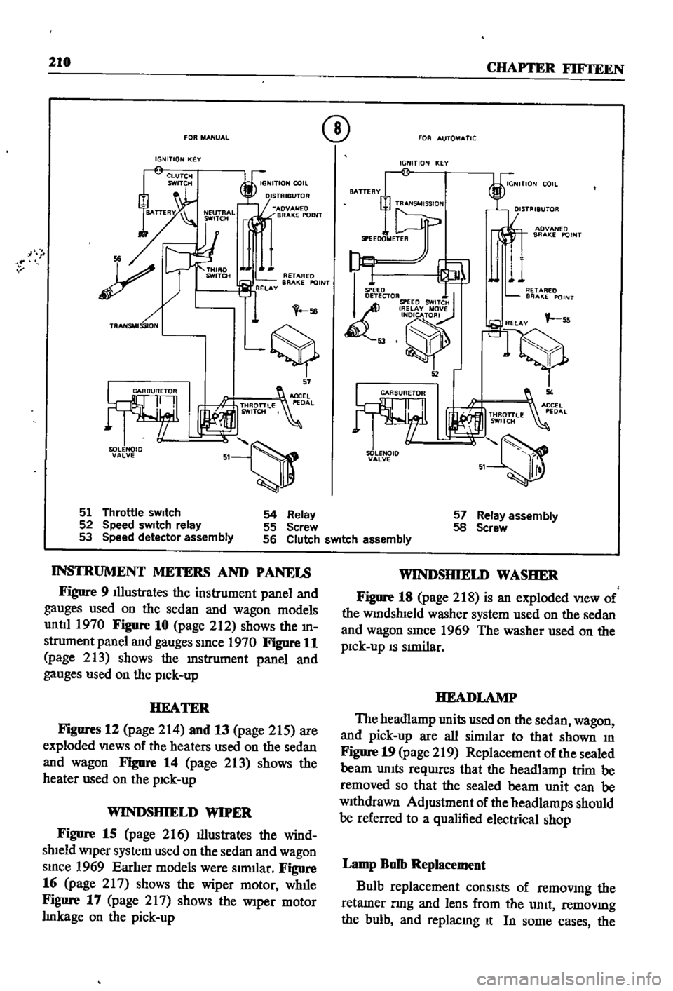
Figure
9
Illustrates
the
instrument
panel
and
gauges
used
on
the
sedan
and
wagon
models
untIl
1970
Figure
10
page
212
shows
the
m
strument
panel
and
gauges
smce
1970
Figure
11
page
213
shows
the
lDstrument
panel
and
gauges
used
on
the
pick
up
HEATER
Figures
12
page
214
and
13
page
215
are
exploded
Views
of
the
heaters
used
on
the
sedan
and
wagon
FigDre
14
page
213
shows
the
heater
used
on
the
pick
up
WINDSHIELD
WIPER
Figure
15
page
216
illustrates
the
wind
shield
Wiper
system
used
on
the
sedan
and
wagon
smce
1969
Earlier
models
were
slrmlar
Figure
16
page
217
shows
the
wiper
motor
wlule
Figure
17
page
2
I
7
shows
the
Wiper
motor
Imkage
on
the
pick
up
WINDSHIELD
WASHER
Figure
18
page
218
is
an
exploded
View
of
the
WindshIeld
washer
system
used
on
the
sedan
and
wagon
smce
1969
The
washer
used
on
the
pick
up
IS
SImilar
HEADLAMP
The
headlamp
units
used
on
the
sedan
wagon
and
pick
up
are
all
similar
to
that
shown
m
Figure
19
page
219
Replacement
of
the
sealed
beam
UnIts
reqwres
that
the
headlamp
trim
be
removed
so
that
the
sealed
beam
unit
can
be
withdrawn
AdJustment
of
the
headlamps
should
be
referred
to
a
qualified
electrical
shop
Lamp
Bulb
Replacement
Bulb
replacement
consIsts
of
removmg
the
retamer
nng
and
lens
from
the
unit
removmg
the
bulb
and
replacmg
It
In
some
cases
the