1968 DATSUN 510 drain bolt
[x] Cancel search: drain boltPage 33 of 252
28
CHAPTER
FIVE
011
gallery
supphes
011
to
the
crankshaft
mam
beanngs
Dnlled
passages
m
the
crankshaft
direct
oil
from
the
mam
bearings
to
the
con
nectmg
rod
beanngs
011
mJected
from
jet
holes
in
the
connectIng
rods
IS
directed
to
the
cylmder
walls
and
piston
pins
0U
dlstnbuted
from
the
mam
gallery
enters
the
cham
tensioner
The
pad
IS
held
against
the
cham
by
011
pressure
and
spnng
tension
The
tmung
chain
receives
011
through
the
Jet
located
near
It
LubncatIon
IS
supphed
to
the
cyhnder
head
mam
011
gallery
through
the
crankshaft
center
beanngs
Camshaft
beanngs
on
the
cyhnder
head
are
fed
directly
from
the
cyhnder
head
mam
gallery
The
rocker
arms
and
valves
are
lubncated
intermittently
by
the
camshaft
011
gallery
and
the
small
channel
at
the
base
CIrcle
portIon
of
each
cam
OllIS
supphed
to
the
cam
shaft
011
gallery
through
the
No
2
and
No
3
camshaft
bearings
OIL
PUMP
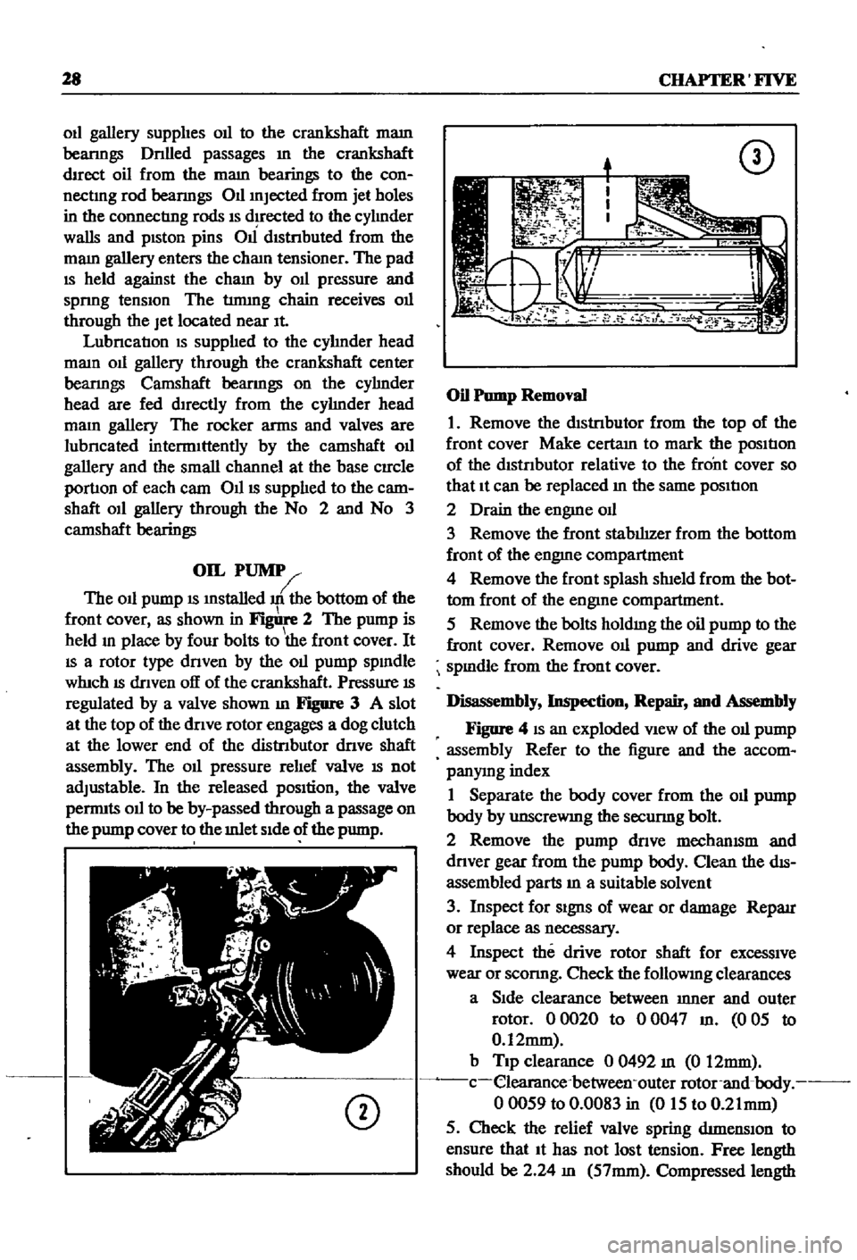
The
011
pump
IS
mstalled
m
the
bottom
of
the
front
cover
as
shown
in
2
The
pump
is
held
m
place
by
four
bolts
to
the
front
cover
It
IS
a
rotor
type
dnven
by
the
011
pump
spmdle
whIch
IS
dnven
off
of
the
crankshaft
Pressure
IS
regulated
by
a
valve
shown
m
Figure
3
A
slot
at
the
top
of
the
dnve
rotor
engages
a
dog
clutch
at
the
lower
end
of
the
distnbutor
dnve
shaft
assembly
The
011
pressure
rehef
valve
IS
not
adjustable
In
the
released
pOSition
the
valve
pernnts
011
to
be
by
passed
through
a
passage
on
the
pump
cover
to
the
mlet
Side
of
the
pump
CD
CD
Oil
Pump
Removal
1
Remove
the
dIStnbutor
from
the
top
of
the
front
cover
Make
certam
to
mark
the
posItIon
of
the
dtstnbutor
relative
to
the
front
cover
so
that
It
can
be
replaced
m
the
same
posItIon
2
Drain
the
engme
od
3
Remove
the
front
stabIhzer
from
the
bottom
front
of
the
engme
compartment
4
Remove
the
front
splash
shIeld
from
the
bot
tom
front
of
the
engine
compartment
5
Remove
the
bolts
holdmg
the
oil
pump
to
the
front
cover
Remove
011
pump
and
drive
gear
spmdle
from
the
front
cover
Disassembly
Inspection
Repair
and
Assembly
Figure
4
IS
an
exploded
VIew
of
the
011
pump
assembly
Refer
to
the
figure
and
the
accom
panymg
index
1
Separate
the
body
cover
from
the
011
pump
body
by
unscreWIng
the
secunng
bolt
2
Remove
the
pump
dnve
mechamsm
and
dnver
gear
from
the
pump
body
Clean
the
dIS
assembled
parts
m
a
suitable
solvent
3
Inspect
for
Signs
of
wear
or
damage
Reparr
or
replace
as
necessary
4
Inspect
the
drive
rotor
shaft
for
excessive
wear
or
sconng
Check
the
followmg
clearances
a
Side
clearance
between
mner
and
outer
rotor
00020
to
00047
m
005
to
0
12mm
b
Tip
clearance
0
0492
m
0
12mm
c
elearance
between
outer
rotor
and
body
00059
to
0
0083
in
015
to
0
21mm
5
Check
the
relief
valve
spring
dtmenslOn
to
ensure
that
It
has
not
lost
tension
Free
length
should
be
2
24
m
57mm
Compressed
length
Page 35 of 252
30
CHAPTER
FIVE
should
be
1
54
m
39mm
If
the
spnng
tension
is
accurate
the
rehef
valve
should
open
at
54
0
to
59
7
lb
1m
3
8
to
4
2
kg
cm
6
Reassemble
the
oil
pump
Make
certain
all
gaskets
are
mounted
flat
to
avoid
leaks
7
Install
the
dnve
spindle
and
the
oil
pump
to
the
front
cover
8
Install
the
distnbutor
in
the
same
relative
locallon
from
which
it
was
removed
If
the
num
ber
1
cyhnder
was
at
top
dead
center
on
the
compression
stroke
the
punch
mark
on
the
dnve
spindle
should
face
toward
the
front
of
the
engine
9
Install
the
front
splash
shield
and
the
front
stablhzer
10
Insert
the
drain
plug
in
the
pan
and
refill
the
engme
11
Oil
pressure
at
idle
should
be
142
to
17
1
lb
lin
1
0
to
1
2
kg
cm
12
Tlghtenmg
torque
values
for
the
oil
pump
mounting
bolts
is
10
8
to
152ft
lb
1
5
to
2
1
kg
m
and
21
69
to
25
31
ft
lb
3
0
to
25
kg
m
for
the
release
valve
cap
nut
Oil
Filter
The
oil
filter
is
mounted
on
the
nght
hand
side
of
the
cyhnder
block
It
IS
a
cartndge
type
with
built
m
gasket
and
threads
onto
the
mounting
spindle
The
filter
should
be
replaced
every
6
000
miles
as
follows
1
Dram
the
engme
oil
Walt
10
15
minutes
before
removmg
oil
filter
to
allow
It
to
dram
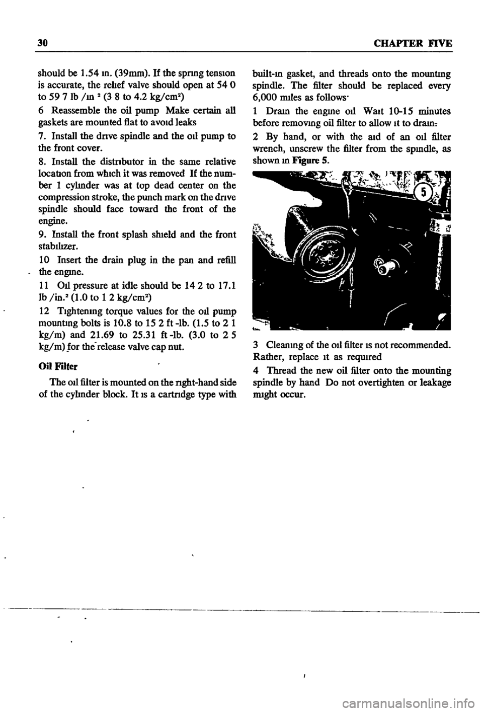
2
By
hand
or
with
the
aid
of
an
oil
filter
wrench
unscrew
the
filter
from
the
spmdle
as
shown
m
Figure
S
3
Cleanmg
of
the
oil
filter
IS
not
recommended
Rather
replace
It
as
reqUIred
4
Thread
the
new
oil
filter
onto
the
mounting
spindle
by
hand
Do
not
overtighten
or
leakage
nught
occur
Page 38 of 252
4l
4111a
78
mml
la78mml
42
4
42
4OIla50mml
t
4544
i
35
45
lIq
D
1
43
45
44
6
1i
45
43
42
41
45
44
46
46
47
8
78mml
I
Tlmmg
Indicator
48
lock
washer
spring
49
Water
Inlet
50
Rubber
cap
51
Rubber
cap
52
Hosa
clamp
53
Inlet
watar
gasket
54
Hex
bolt
55
lock
washer
spring
56
Connector
57
011
filter
cartndge
58
front
engme
cover
59
61
Bloel
cyllndelllner
18
15
58
57
1
Cylinder
block
assembly
2
Main
beanng
bolt
3
Dowel
4
Block
dowel
5
Block
dowel
6
Block
to
transmIssIon
case
dowel
7
Tlmmg
chaIn
covar
dowel
8
Welch
plug
9
Taper
plug
10
Crankcase
011
seal
11
Bearing
011
seal
12
Drain
plug
13
011
pressure
sWitch
14
011
level
gauge
guide
15
Oll
evel
gauga
r1
26
54
25
011
pan
gasket
26
Hax
bolt
27
lock
Sprl
ng
washer
28
011
cooler
hose
clamp
29
Hose
cl
mp
30
Tube
clamp
31
Tube
clamp
32
Clamp
spacer
33
Hex
bolt
34
Washer
35
Crankcase
011
seel
36
Waler
pump
dowel
37
Water
pump
dowel
38
RIght
hand
front
caver
gasket
39
left
hand
front
cover
gasket
40
Hex
bolt
41
Hex
bolt
42
lock
washer
spnng
43
Hex
bolt
44
Hex
bolt
45
Lock
washer
spring
46
Tlmmg
Indicator
47
IndIcator
rivet
22
16
23
Drain
plug
washer
24
Dram
plug
e
l
lIlI
1M
1M
Page 43 of 252
38
CHAPTER
SIX
EMISSION
CONTROL
DEVICES
All
Datsuns
have
a
sealed
type
of
crankcase
emISSion
control
device
and
an
exhaust
emISsion
control
deVice
Models
sold
m
Cahfornla
smce
1970
also
have
an
evaporative
emisSion
control
deVice
An
rmportant
part
of
the
exhaust
control
device
is
the
air
pump
located
at
the
bottom
left
hand
side
of
the
engme
It
IS
dnven
by
a
belt
off
of
the
crankshaft
pulley
and
supphes
air
to
the
exhaust
system
In
1972
an
electric
blower
in
corporated
m
the
air
cleaner
replaced
the
mechanical
pumI
ENGINE
REMOVAL
Expenence
has
shown
It
IS
easier
to
remove
the
engine
and
the
transmission
as
a
smgle
UnIt
than
to
remove
the
engme
alone
Once
the
en
gine
and
transmiSSIon
are
out
of
the
vehIcle
the
tranSmIssion
can
be
detached
from
the
engme
To
remove
the
engme
transmISsion
proceed
as
follows
1
Scribe
ahgnment
marks
on
the
hood
around
the
hmges
ThIS
will
make
remstallatlon
eaSIer
2
Remove
the
two
bolts
that
secure
each
hInge
and
remove
the
hood
It
is
not
necessary
to
re
move
the
hood
support
from
the
engme
firewall
3
DISconnect
the
lower
radIator
hose
from
the
right
hand
SIde
of
the
engine
and
at
the
bottom
of
the
radIator
ThIS
will
pernnt
coolant
to
dram
from
the
engme
and
the
radIator
4
Remove
the
draIn
plugs
from
the
engine
pan
and
translIDSsIon
and
completely
dram
lubn
cants
Into
suitable
contamers
5
DISconnect
the
battery
cables
from
the
bat
tery
loosen
the
two
hold
down
clamps
and
re
move
the
battery
NOTE
The
location
and
number
of
hoses
to
be
removed
from
the
air
cleaner
varies
from
model
to
model
It
IS
normally
easier
to
remove
the
hoses
from
the
sources
rather
than
try
to
dISconnect
them
from
yndemeath
the
air
cleaner
The
1972
model
Will
requlre
dlsconnectlOn
of
the
electrica1
cirCUit
In
the
air
cleaner
system
wing
nut
from
the
top
of
the
air
cleaner
and
remove
the
aIr
cleaner
7
DIsconnect
the
upper
radiator
hose
from
the
radiator
and
the
thermostat
housmg
Remove
the
hose
8
Disconnect
the
two
heater
hoses
from
the
nght
hand
side
of
the
engme
TIe
these
bac
so
they
won
t
interfere
with
removal
of
the
engme
9
Remove
the
radIator
grille
by
unscrewing
all
mountmg
screws
10
Remove
the
four
mounting
screws
holding
the
fan
shield
to
the
backside
of
the
radiator
11
Remove
the
four
mountmg
bolts
holdIng
the
radiator
In
place
In
automatic
tranSmISsion
models
dISconnect
the
two
transnnsslOn
oIl
cooler
lInes
from
the
bottom
of
the
radiator
Pull
the
radiator
straight
up
to
remove
Remove
the
fan
shield
12
Loosen
the
adjustment
and
mounting
bolts
from
the
retamIng
brackets
on
the
alternator
and
air
pump
If
so
eqwpped
The
alternator
is
lo
cated
at
the
bottom
nght
hand
Side
of
the
engme
and
the
air
pump
on
the
lower
left
hand
Side
13
Loosen
tenSIon
on
the
two
dnve
belts
re
move
the
belts
from
the
alternator
and
air
pump
and
then
from
the
fan
pulleys
14
Remove
the
bolts
holdIng
the
fan
and
pulley
to
the
water
pump
assembly
and
remove
the
fan
and
pulley
15
DISconnect
the
fuel
hne
from
the
fuel
pump
16
DIsco
ect
accelerator
control
linkage
and
choke
WIre
at
the
carburetor
17
Disconnect
the
wiring
from
the
starter
motor
alternator
Ignition
coIl
oIl
pressure
switch
and
temperature
transmItting
unit
NOTE
The
following
steps
are
per
formed
from
under
the
car
lack
up
the
front
of
the
car
and
position
stands
under
the
front
support
points
to
proVide
working
room
under
the
vehicle
WARNING
Never
climb
under
a
vehicle
that
is
supported
by
the
lack
only
If
stands
are
not
avflllable
sturdy
wooden
blocks
can
be
U3ed
6
Disconnect
all
hoses
that
lead
to
the
air
cleaner
remove
two
bolts
that
hold
the
air
cleaner
to
its
mountmg
bracket
unscrew
the
18
Remove
two
bolts
holdIng
the
clutch
operat
Ing
cylInder
to
the
flywheel
hOUSIng
shown
m
Page 64 of 252

ENGINE
59
2
Coat
the
pan
gasket
on
both
sides
With
gasket
compound
and
attach
the
oil
pan
to
the
cyhnder
block
Torque
as
specIfied
Manifold
and
Carburetor
Installation
1
Install
the
mtake
and
exhaust
manIfolds
WIth
associated
gasket
to
the
cylmder
head
2
Mount
the
carburetor
and
gasket
to
the
mtake
manIfold
2
Adjust
all
mtake
and
exhaust
valves
to
the
specIfied
clearance
for
a
cold
engme
Clutch
Assembly
Installation
CAUTION
Take
extreme
care
not
to
get
grease
or
011
on
the
clutch
or
flywheel
frlc
hon
contact
surfaces
1
Place
the
clutch
disc
assembly
on
the
flywheel
With
the
longer
chamfered
splmed
end
of
the
dISC
toward
the
transmISSion
2
Visually
align
or
use
a
dummy
splmed
dnve
shaft
to
ahgn
the
diSC
assembly
With
the
flywheel
pilot
beanng
3
Install
and
tighten
the
SIX
bolts
holdmg
the
clutch
cover
assembly
to
the
flywheel
Tighten
the
bolts
a
turn
each
tune
by
diagonal
pattern
until
they
are
tight
Tlghtenmg
torque
should
be
174
to
188ft
lbs
24
to
2
6
kg
m
NOTE
There
are
two
dowels
on
the
flywheel
to
locate
the
clutch
cover
4
Remove
dummy
shaft
If
used
after
the
above
bolts
are
fully
tightened
5
Refit
the
release
bearing
and
translI11Ssion
case
Miscellaneous
Installation
1
Connect
the
fuel
hose
on
the
front
part
of
the
engme
to
the
fuel
pump
and
to
the
carburetor
2
Gap
the
spark
plugs
and
mstall
them
usmg
new
gaskets
3
Coat
the
rocker
arm
cover
gasket
With
sealer
and
position
It
on
the
cylmder
head
4
Install
the
rocker
arm
cover
and
tighten
the
two
thumb
screws
that
hold
it
m
place
5
Install
distrIbutor
makmg
certam
that
the
notch
on
the
distributor
shaft
assembly
mates
With
the
drive
spmdle
Ahgn
the
location
marks
made
dunng
disassembly
so
that
the
distrIbutor
is
positioned
as
before
6
Install
and
tighten
the
bolts
which
hold
the
dIStributor
to
the
front
cover
7
Install
pomts
condenser
and
rotor
8
Replace
distrIbutor
cap
and
attach
spark
plug
Wires
m
the
correct
sequence
Make
certain
that
all
wires
are
firmly
seated
m
the
distrIbutor
cap
and
attached
securely
to
the
spark
plugs
9
HOISt
the
engme
assembly
from
the
work
stand
10
Install
the
alternator
bracket
alternator
and
engme
mounts
to
the
block
11
Install
the
IgnItIon
coil
oil
filter
oil
pressure
SWitch
dipstick
and
water
drain
plug
12
Connect
the
vacuum
Ime
between
the
dis
trIbutor
and
carburetor
13
Connect
the
transIDlSSlOn
to
the
engine
prior
to
mstallatIon
m
the
vehicle
Engine
Installation
Installation
is
the
reverse
of
the
procedures
followed
m
removal
Be
certaIn
thatlall
battery
connections
are
made
that
water
hoses
are
se
cured
wmng
IS
connected
properly
and
that
all
required
bolts
and
mounts
are
mstalled
and
tightened
Replace
the
radiator
fan
belts
and
radiator
shroud
Fill
the
engme
With
the
proper
grade
of
oil
and
the
radiator
With
recommended
coolant
Install
the
hood
to
the
hInges
according
to
the
marks
made
dUrIng
removal
SERVICE
DATA
AND
SPECIFICATIONS
Table
1
covers
servIce
data
and
engme
Speci
fications
Page 81 of 252
76
CHAPTER
SEVEN
Carburetor
Assembly
Assembly
is
the
reverse
of
dISassembly
Make
certam
all
gaskets
are
mounted
flat
Be
careful
not
to
use
force
In
assembly
Make
certam
that
all
Interlock
lInks
operate
smoothly
FUEL
TANK
Description
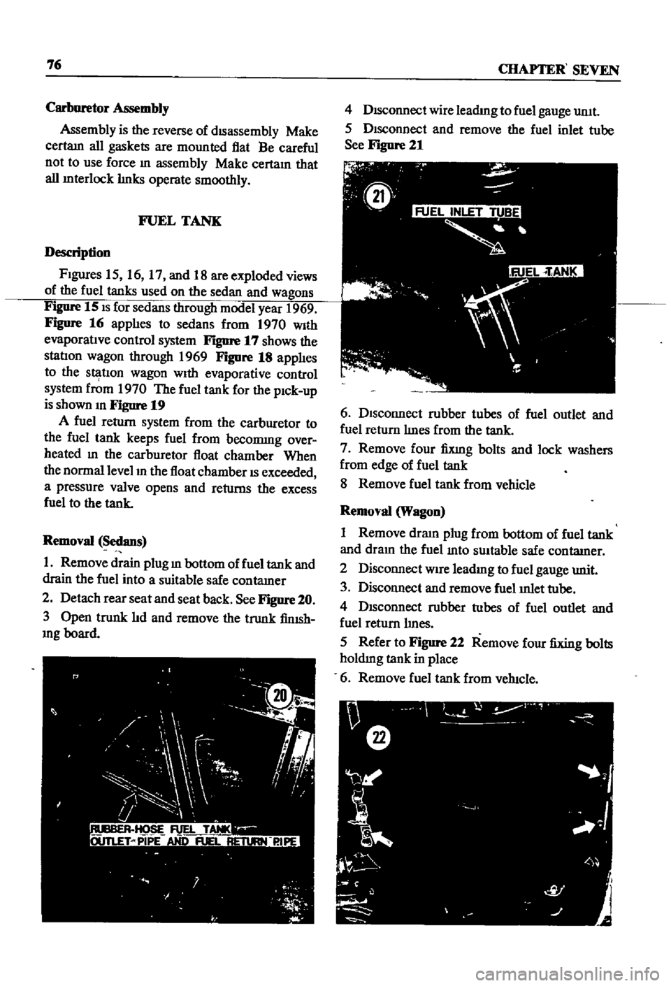
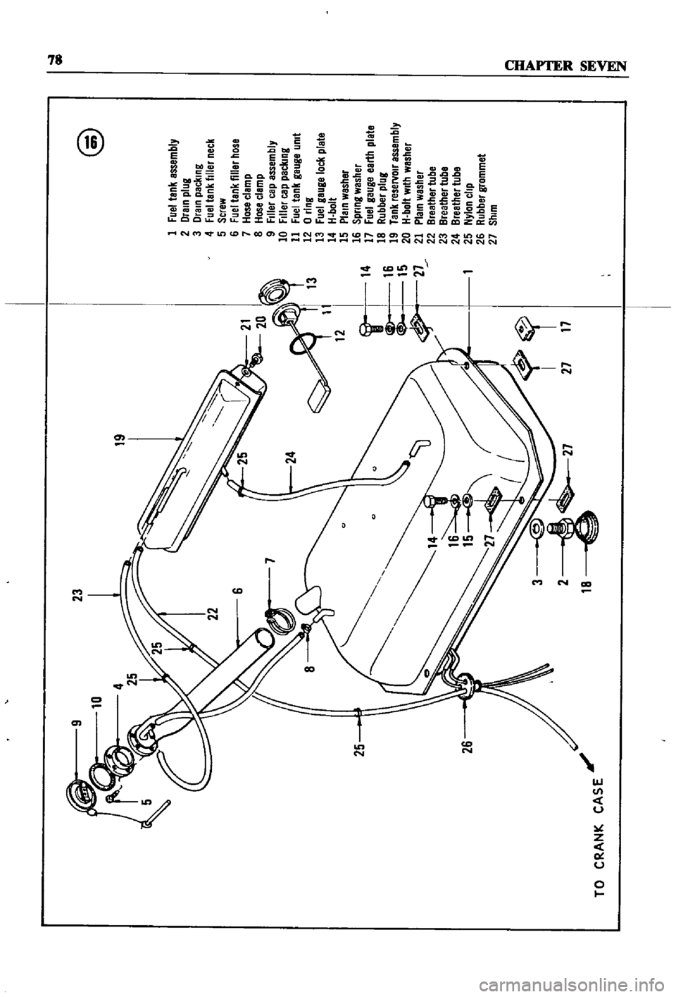
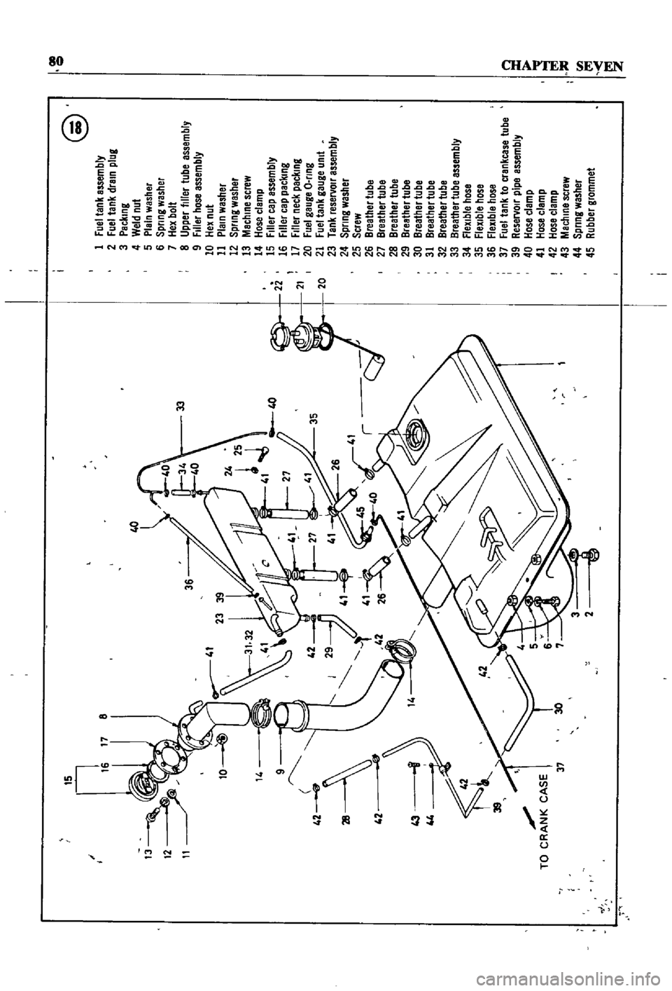
FIgures
15
16
17
and
18
are
exploded
views
of
the
fuel
tanks
used
on
the
sedan
and
wagons
Figure
15
IS
for
sedans
through
model
year
1969
Figure
16
applIes
to
sedans
from
1970
With
evaporative
control
system
F
q
nre
17
shows
the
statIon
wagon
through
1969
Figure
18
applIes
to
the
statIon
wagon
WIth
evaporative
control
system
f
m
1970
The
fuel
tank
for
the
pIck
up
is
shown
m
Figure
19
A
fuel
return
system
from
the
carburetor
to
the
fuel
tank
keeps
fuel
from
becommg
over
heated
m
the
carburetor
float
chamber
When
the
normal
level
m
the
float
chamber
IS
exceeded
a
pressure
valve
opens
and
returns
the
excess
fuel
to
the
tank
Removal
Sedans
1
Remove
drain
plug
m
bottom
of
fuel
tank
and
drain
the
fuel
into
a
suitable
safe
contamer
2
Detach
rear
seat
and
seat
back
See
Figure
20
3
Open
trunk
lId
and
remove
the
trunk
finISh
mg
board
4
DIsconnect
wire
leadmg
to
fuel
gauge
umt
5
DIsconnect
and
remove
the
fuel
inlet
tube
See
Figure
21
6
DIsconnect
rubber
tubes
of
fuel
outlet
and
fuel
return
lInes
from
the
tank
7
Remove
four
fixmg
bolts
and
lock
washers
from
edge
of
fuel
tank
8
Remove
fuel
tank
from
vehicle
Removal
Wagon
1
Remove
draIn
plug
from
bottom
of
fuel
tank
and
dram
the
fuel
mto
swtable
safe
contatner
2
Disconnect
WIre
leadIng
to
fuel
gauge
unit
3
Disconnect
and
remove
fuel
mlet
tube
4
DISconnect
rubber
tubes
of
fuel
outlet
and
fuel
return
lInes
5
Refer
to
Figure
22
Remove
four
fixing
bolts
holdmg
tank
in
place
6
Remove
fuel
tank
from
veh1c1e
Page 83 of 252
23
19
21
20
I
13
11
12
I
14
L
1
A
21
I
26
TO
CRANK
CASE
@
1
Fuel
tank
assembly
2
Drain
plug
3
Drain
packing
4
Fuel
tank
filler
neck
5
Screw
6
Fuel
tank
filler
hose
7
Hose
clamp
8
Hose
clamp
9
Filler
cap
assembly
10
Filler
cap
packing
11
Fuel
tank
gauge
umt
12
0
ring
13
Fuel
geuge
loc
l
plate
14
H
bolt
15
Plain
washer
16
Spnng
wesher
17
Fuel
gauge
earth
plale
18
Rubber
plug
19
Tank
reseNOlr
essembly
20
H
bolt
With
washer
21
Plein
washer
22
Breather
tube
23
Breather
tube
24
Breether
tube
25
Nylon
clip
26
Rubber
grommet
27
Shim
QD
g
j
Page 85 of 252
QO
@
15
I
1
Fuellank
assembly
17
8
2
Fuel
tank
drain
plug
3
Packing
4
Weld
nul
5
Plain
washer
6
Spllng
washer
7
Hex
bolt
33
8
Upper
filler
tube
assembly
9
Filler
hose
assembly
10
Hex
nut
11
Plain
washer
U
12
Spllng
washer
25
13
Machine
screw
rt
41
40
14
Hose
clamp
2i
15
Filler
cap
assembly
27
J
16
Filler
cap
packing
L
1
17
Filler
neck
packing
21
35
20
Fuel
gauge
O
lIng
20
21
Fuel
tank
gauge
Unit
23
Tank
reservoll
assembly
24
Spllng
washer
25
Screw
26
Breather
tube
27
Breather
tube
28
Breather
lube
29
Breather
tube
30
Breather
tube
31
Breather
tube
32
Breather
tube
33
Breather
tube
assembly
34
flexible
hose
35
Flexible
hose
36
flexible
hose
37
Fuel
tank
to
crankcase
tube
a
39
Reservoll
pipe
assembly
TO
CR
CASE
I
Y
40
Hose
clamp
41
Hose
clamp
I
42
Hose
clamp
37
30
1
43
Machine
screw
44
Spllng
washer
rIJ
45
Rubber
grommet
I
fi
j