1968 DATSUN 510 drain bolt
[x] Cancel search: drain boltPage 95 of 252
90
CHAPTER
EIGHT
degrees
C
The
maXImum
WIdth
of
the
thermo
stat
openIng
should
be
0315
In
8mm
3
If
the
thermostat
IS
defectIve
or
If
you
have
an
doubts
about
It
mstall
a
new
one
4
When
Installmg
the
thermostat
m
the
hous
Ing
be
certaIn
to
place
the
spnng
end
down
Coat
both
SIdes
of
the
gasket
WIth
sealer
to
pre
vent
leaks
and
tIghten
the
mountlng
nuts
securely
RADIATOR
The
radIator
IS
of
conventional
desIgn
A
draIn
cock
IS
proVIded
at
the
bottom
back
to
perrmt
drainIng
The
system
IS
pressurized
and
the
rehef
valve
incorporated
In
the
filler
cap
mamtains
the
pressure
at
approximately
12
8
Ib
in
0
9
kg
cm
Coolant
capacity
is
1
691
gallons
6
4
lIters
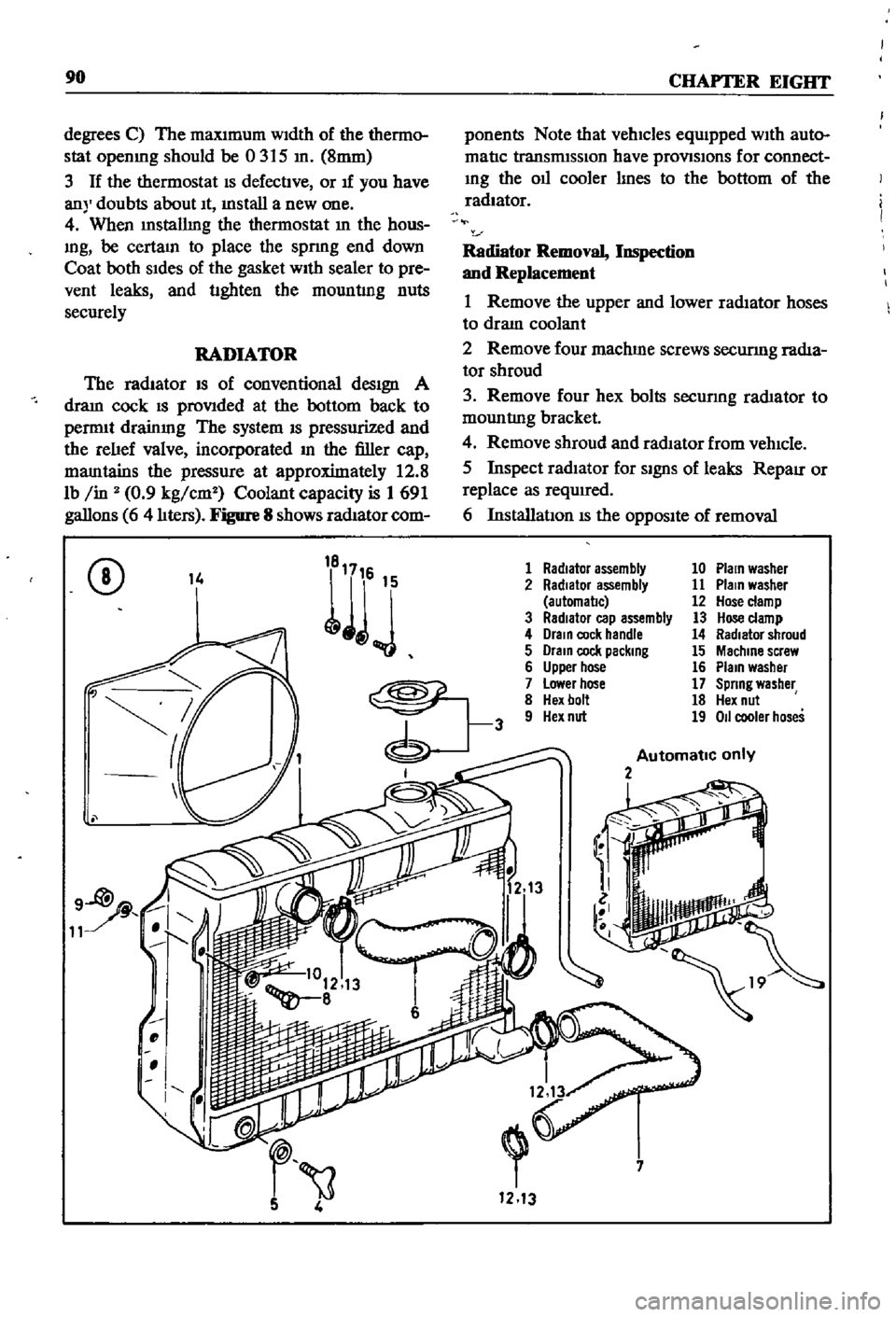
Figure
8
shows
radIator
com
ponents
Note
that
vehicles
equIpped
WIth
auto
matIc
transmISSIon
have
provlSlons
for
connect
Ing
the
011
cooler
lInes
to
the
bottom
of
the
radiator
Radiator
Removal
Inspection
and
Replacement
1
Remove
the
upper
and
lower
radIator
hoses
to
draIn
coolant
2
Remove
four
machme
screws
securmg
radIa
tor
shroud
3
Remove
four
hex
bolts
secunng
rad1ator
to
mountlng
bracket
4
Remove
shroud
and
radIator
from
vehIcle
5
Inspect
radIator
for
SignS
of
leaks
RepaIr
or
replace
as
required
6
InstallatIon
IS
the
OppOSIte
of
removal
CD
14
1
Radiator
assembly
10
Plain
washer
2
Radiator
assembly
11
Plain
washer
automal1c
12
Hose
clamp
3
RadIator
cap
assembly
13
Hose
clamp
4
Drain
cock
handle
14
Radiator
shroud
5
Drain
cock
packing
15
Machine
screw
6
Upper
hose
16
Plain
washer
7
Lower
hose
17
Spring
washer
8
Hex
bolt
18
Hex
nut
9
Hex
nut
19
011
cooler
hoses
Automatic
only
2
i
7
1213
Page 135 of 252
130
CHAPTER
ELEVEN
master
cylInder
operatlng
cylinder
and
with
drawal
lever
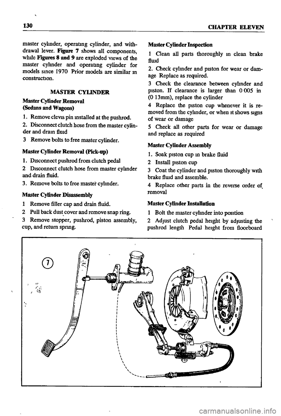
Figure
7
shows
all
components
whlle
Figures
8
and
9
are
exploded
VIews
of
the
master
cylmder
and
operatIng
cylinder
for
models
smce
1970
Prior
models
are
similar
In
construction
MASTER
CYLINDER
Master
Cylinder
Removal
Sedans
and
Wagons
1
Remove
cleVIS
pin
mstalled
at
the
pushrod
2
Disconnect
clutch
hose
from
the
master
cylin
der
and
dram
flwd
3
Remove
bolts
to
free
master
cylinder
Master
Cylinder
Removal
Pick
up
1
DIsconnect
pushrod
from
clutch
pedal
2
DIsconnect
clutch
hose
from
master
cylInder
and
drain
fluid
3
Remove
bolts
to
free
master
cylInder
Master
Cylinder
Disassembly
1
Remove
filler
cap
and
drain
fluid
2
Pull
back
dust
cover
and
remove
snap
ring
3
Remove
stopper
pushrod
piston
assembly
cup
and
return
spnng
CD
i
Master
Cylinder
Inspection
1
Clean
all
parts
thoroughly
In
clean
brake
flwd
2
Check
cylInder
and
pISton
for
wear
or
dam
age
Replace
as
required
3
Check
the
clearance
between
cylInder
and
pIston
If
clearance
is
larger
than
0
005
in
0
13mm
replace
the
cylinder
4
Replace
the
pISton
cup
whenever
it
is
re
moved
from
the
cylInder
or
when
It
shows
SIgnS
of
wear
or
damage
5
Check
all
other
parts
for
wear
or
damage
and
replace
as
required
Master
Cylinder
Assembly
1
Soak
piston
cup
m
brake
fluid
2
Install
pIston
cup
3
Coat
the
cylinder
and
pIston
thoroughly
WIth
brake
flwd
and
assemble
4
Replace
other
parts
in
the
reverse
order
of
removal
Master
Cylinder
Installation
1
Bolt
the
master
cylInder
into
pOSItion
2
Adjust
clutch
pedal
heIght
by
adjusting
the
pushrod
length
Pedal
heIght
from
floorboard
Page 144 of 252
CLUTCH
TRANSMISSION
AND
DRIVESHAFI
139
@
1
Re
erse
gear
2
Re
erse
shaft
3
Reverse
gear
4
Snep
nng
5
Thrust
washer
6
Reverse
gear
needle
beanng
7
Counter
gear
8
Counter
shaft
9
Counter
spacer
10
Needle
bearing
assembly
11
Thrust
washer
12
Thrust
washer
J
f
I
I
I
I
I
I
I
I
I
I
J
I
I
i
I
f
4
rm
9
13
MaIO
dnve
gear
14
MaIO
dn
e
beanng
15
MaIO
drl
e
spacer
16
MelO
drl
e
snap
ring
17
MaIO
shaft
18
steel
ball
19
Thrust
washer
20
MaIO
shaft
needle
bearing
21
Meln
shaft
bushlOg
22
MaIO
shaft
flm
gear
23
Baulk
nng
24
Sh
ftlOg
Insert
25
Spread
sprlOg
9
1
Remove
the
drain
plug
and
dram
the
trans
rmSSlon
gear
011
Into
a
SUItable
container
2
Remove
the
dust
cover
and
release
the
re
tainer
spring
securing
the
Withdrawal
lever
Re
move
the
lever
and
release
bearing
from
the
clutch
housmg
3
Remove
the
pIn
securing
the
strikmg
rod
to
the
control
lever
and
remove
the
control
lever
4
Remove
five
front
cover
securing
bolts
and
the
front
cover
i
j
5
Remove
14
hex
bolts
and
washers
from
bot
tom
cover
Remove
bottcifu
cover
from
trans
I
I
I
I
I
I
i
i
J
34
34
26
Synchronize
hub
27
CoupllOg
slee
e
28
MaIO
shaft
needle
beanng
29
Second
gear
assembly
30
MaIO
shaft
needle
beanng
31
Third
speed
gear
32
Baulk
nng
33
ShlftlOg
IOsert
34
Spread
spring
35
Synchro
hub
36
Slee
e
coupllOg
37
Snep
nng
38
MaIO
shaft
pilot
beanng
39
Main
shaft
bearing
40
MaIO
shaft
snap
ring
41
Re
erse
maIO
gear
and
hub
set
42
Rwerse
hub
maIO
shaft
43
Speedometer
gear
44
Steel
ball
45
MaIO
sheft
loc
l
washer
46
MaIO
shaft
nut
28
iy
25
25
21
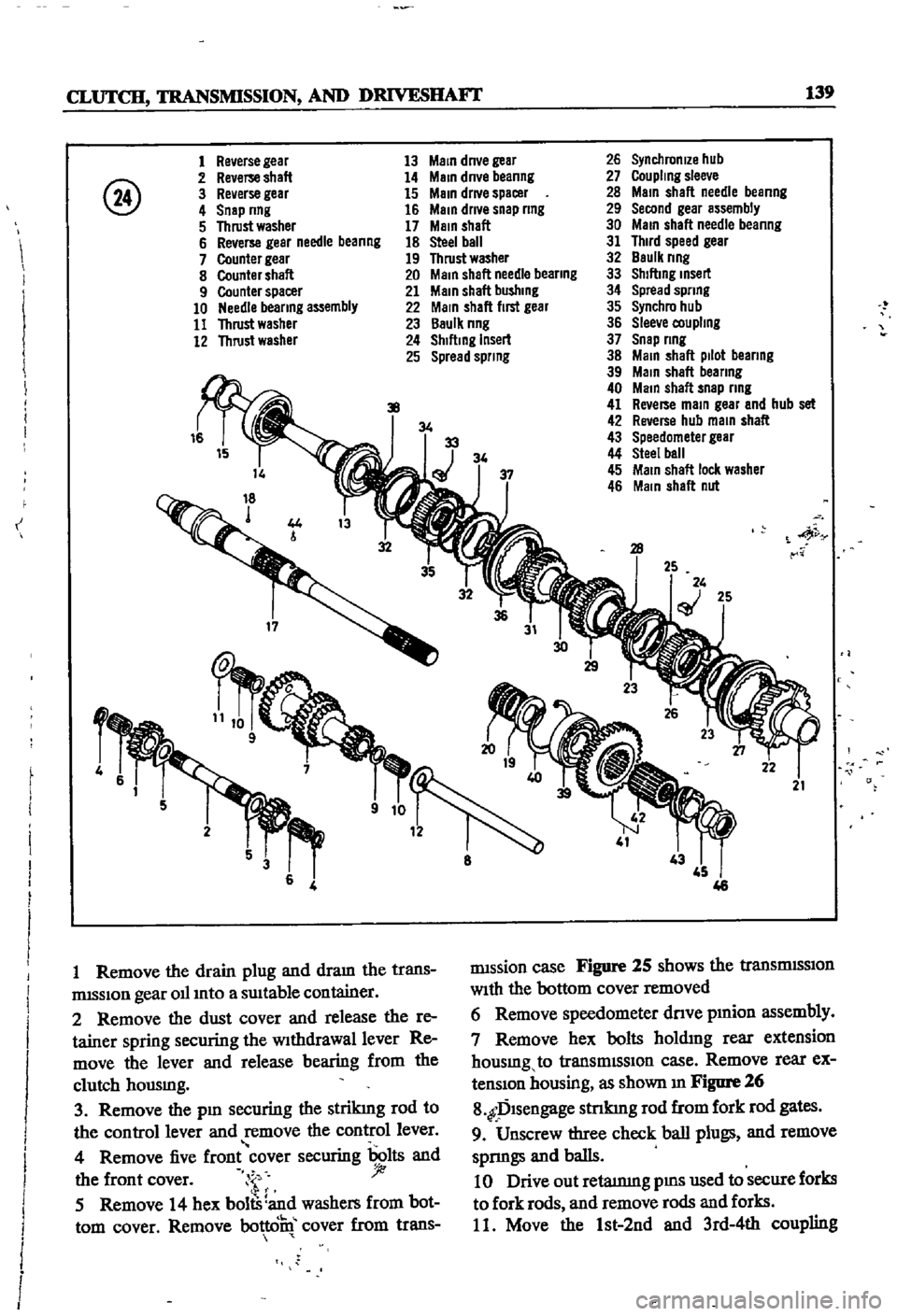
rmssion
case
Figure
25
shows
the
tranSmISSIon
With
the
bottom
cover
removed
6
Remove
speedometer
dnve
pmion
assembly
7
Remove
hex
bolts
holdmg
rear
extension
housmg
to
transmISSIon
case
Remove
rear
ex
tenSIon
housing
as
shown
m
Figure
26
8
fDlsengage
stnkmg
rod
from
fork
rod
gates
9
Unscrew
three
check
ball
plugs
and
remove
sprmgs
and
balls
10
Drive
out
retatnmg
pms
used
to
secure
forks
to
fork
rods
and
remove
rods
and
forks
11
Move
the
1st
2nd
and
3rd
4th
coupling
Page 149 of 252
144
CHAPTER
ELEVEN
TAANSMISSlON
SERVICE
DATA
AND
SPECIRCATIONS
Table
2
r
General
SpecificatIOns
Gear
Ratlo
1st
2nd
3rd
4th
Reverse
011
capacity
Detail
SpeCIfications
Gear
backlash
Replacement
standard
Gear
end
play
Balk
ring
cone
clearance
Replacement
standard
5
tl
viV
t
O
5
0
If
3657
2558
1419
1000
3638
3
6
pints
Tightening
Torque
ft
Ib
kg
m
Engine
transmission
installation
bolt
Front
cover
transmission
installation
bolt
Rear
extensIon
transmIssion
installation
bolt
Main
shaft
tlghtel
lng
bolt
Companion
flange
tightening
nut
Rear
engine
mount
installation
bolt
Filler
plug
Drain
plug
Back
up
lamp
sWItch
Bottom
cover
bolt
Speedometer
pinion
bolt
Interlock
plug
Operating
lever
Reverse
check
Control
lever
installatIOn
bolt
00020
to
0
0039
In
005
to
0
10mm
o
0079
In
0
20mm
o
0020
to
0
0059
In
0
05
to
0
15mm
00472
to
0
0630
In
1
2
to
1
6mm
00315
In
08mm
174
to
20
2
24
to
2
8
5
8
to
7
2
0
8
to
1
0
10
1
to
130
1
4
to
1
8
57
8t079
5
80to
11
0
72
3
to
101
2
100
to
140
239
to
27
5
3
3
to
38
18
1
to
25
3
25
to
3
5
14
5
to
21
7
20
to
3
0
14
5
to
21
7
2
0
to
3
0
5
8
to
7
2
0
8
to
1
0
2
2
to
2
9
03
to
0
4
123
to
15
2
1
7
to
2
1
22
to
2
9
0
3
to
0
4
14
5
to
21
7
20
to
3
0
13
7
to
15
9
1
9
to
2
2
DRIVE
SHAFf
Descripti
ll
TIie
dnve
shaft
on
the
sedan
and
wagon
is
a
smgle
plece
tubular
steel
unit
The
pick
up
uses
a
two
pIece
umt
Joined
by
a
Journal
assembly
unIversal
Joint
UnIversal
Jomts
connect
the
drive
shaft
ends
to
the
transmissIOn
and
d1f
ferentIal
The
Jomts
consist
of
the
Journal
as
sembly
yoke
sleeve
and
yoke
flange
Figure
40
is
an
explOded
VIew
of
the
dnve
shaft
used
on
the
sedan
and
agon
Figure
41
page
146
shows
the
dnve
shaft
used
on
the
pIck
up
The
pIck
up
has
a
grease
mpple
on
the
dnve
shaft
to
lubncate
the
dnve
shaft
spline
The
sedan
and
wagon
are
not
so
equipped
The
uni
versal
Jomts
shouldebe
removed
and
lubncated
every
24
000
rmles
Removal
1
Release
the
handbrake
j
2
Jack
up
the
rear
of
the
vehIcle
and
support
on
stands
3
Loosen
the
end
clamps
on
the
exhaust
pipe
and
turn
the
exhaust
pIpe
and
premuffier
to
the
left
so
that
dnve
shaft
can
be
removed
sedan
4
Remove
handbrake
rear
cable
adjustIng
nut
from
the
adjuster
DIsconnect
left
hand
cable
from
the
adjuster
sedan
5
DIsconnect
rear
flange
yoke
from
the
com
panIon
flange
by
removmg
the
nuts
and
bolts
See
Figure
42
CAUTION
Be
careful
not
to
let
end
of
dnve
shaft
drop
to
ground
Lower
It
gently
6
Pull
the
dnve
shaft
backwards
away
from
the
transmISSIon
Remove
the
dnve
shaft
as
soon
as
It
IS
clear
of
the
transmISSIon
Make
cert
n
to
support
both
ends
of
the
shaft
duriftgi
mb
sedan
and
wagon
v
4
1tr
l
t
t
Page 154 of 252
CHAPTER
TWELVE
DIFFERENTIAL
REAR
AXLE
AND
REAR
SUSPENSION
The
dIfferential
rear
axle
and
rear
suspen
sIon
dIffer
for
the
various
models
ThIS
chapter
deals
WIth
each
separately
Due
to
the
need
for
SpecIal
tools
and
exper
Ience
to
dIsassemble
and
repaIr
these
unItS
the
followmg
procedures
generally
cover
removal
InspectIon
and
replacement
only
If
mechanIcal
dIfficultIes
eXIst
WIthIn
the
dIfferentIal
and
rear
axle
components
refer
servIce
and
repair
to
a
Datsun
dealer
or
competent
garage
DIFFERENTIAL
SEDAN
The
cast
Iron
dIfferentIal
assembly
used
in
the
sedan
is
shown
in
Figure
1
next
page
Proper
lubncatlOn
of
the
gear
housmg
IS
essen
tIal
Check
lubncant
every
3
000
mlles
and
re
plenISh
as
necessary
Drain
and
refill
lubncant
at
least
every
30
000
miles
Differential
Removal
Sedan
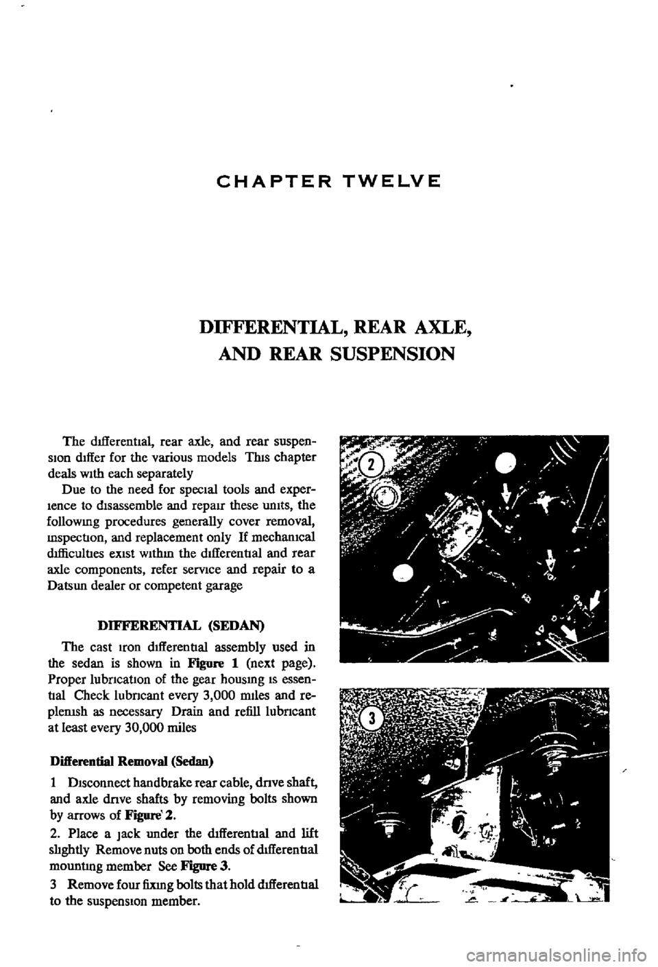
1
DISconnect
handbrake
rear
cable
dnve
shaft
and
axle
dove
shafts
by
removing
bolts
shown
by
arrows
of
Figure
2
2
Place
a
Jack
under
the
dIfferential
and
lift
slIghtly
Remove
nuts
on
both
ends
of
dtfferentIal
mountlng
member
See
Figure
3
3
Remove
four
fixIng
bolts
that
hold
dIfferentIal
to
the
suspensIon
member
Page 163 of 252
158
CHAPTER
TWELVE
REAR
AXLE
AND
SUSPENSION
WAGON
The
rear
axle
is
a
semI
f1oatlng
type
The
rear
wheel
bearmgs
are
presealed
and
do
not
require
penodlc
servIcmg
However
whenever
new
bearmgs
are
Installed
they
should
be
packed
v
lth
wheel
beanng
grease
durmg
InstallatIon
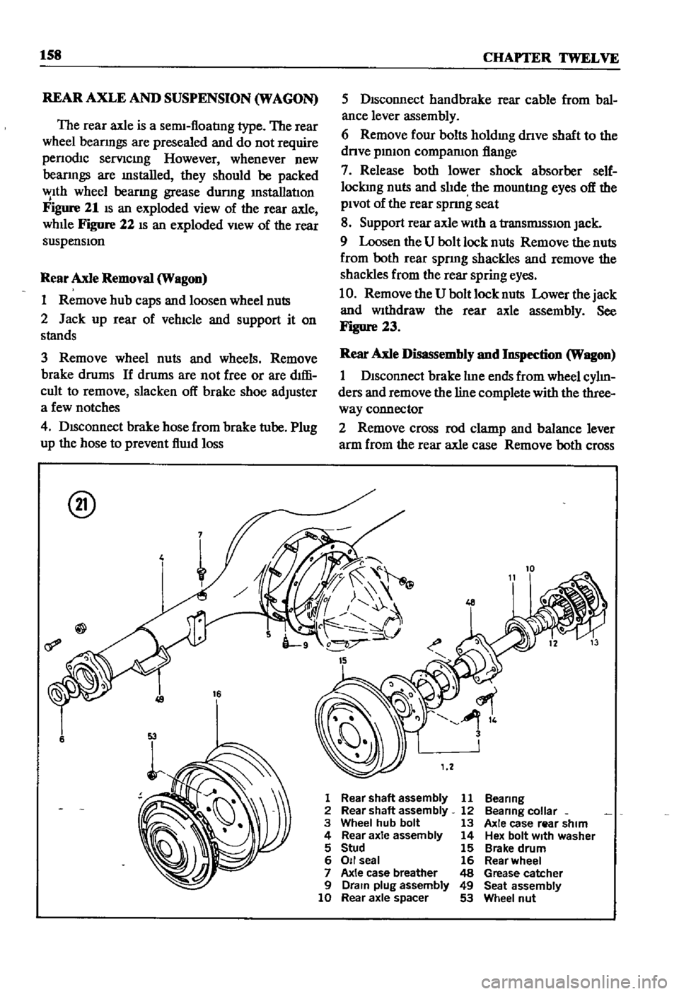
Figure
21
IS
an
exploded
view
of
the
rear
axle
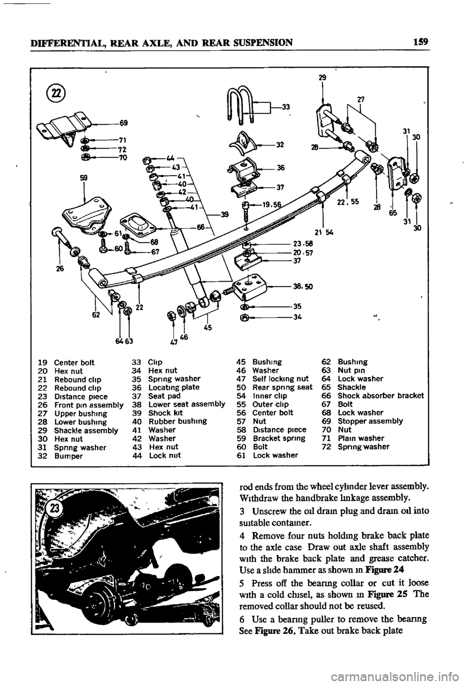
whlle
Figure
22
IS
an
exploded
VIew
of
the
rear
suspensIon
Rear
Axle
Removal
Wagon
1
Remove
hub
caps
and
loosen
wheel
nuts
2
Jack
up
rear
of
vehIcle
and
support
it
on
stands
3
Remove
wheel
nuts
and
wheels
Remove
brake
drums
If
drums
are
not
free
or
are
dIffi
cult
to
remove
slacken
off
brake
shoe
adjuster
a
few
notches
4
DISconnect
brake
hose
from
brake
tube
Plug
up
the
hose
to
prevent
f1Uld
loss
@
4
16
6
5
DIsconnect
handbrake
rear
cable
from
bal
ance
lever
assembly
6
Remove
four
bolts
holdmg
dnve
shaft
to
the
dnve
pmlon
compamon
flange
7
Release
both
lower
shock
absorber
self
lockmg
nuts
and
slIde
the
mountlng
eyes
off
the
PIvot
of
the
rear
spnng
seat
8
Support
rear
axle
wIth
a
transrmsslOn
Jack
9
Loosen
the
U
bolt
lock
nuts
Remove
the
nuts
from
both
rear
spnng
shackles
and
remove
the
shackles
from
the
rear
spring
eyes
10
Remove
the
U
bolt
lock
nuts
Lower
the
jack
and
WIthdraw
the
rear
axle
assembly
See
Figure
23
Rear
Axle
Disassembly
and
Inspection
Wagon
1
DIsconnect
brake
lIne
ends
from
wheel
cylIn
ders
and
remove
the
line
complete
with
the
three
way
connector
2
Remove
cross
rod
clamp
and
balance
lever
arm
from
the
rear
axle
case
Remove
both
cross
1
Rear
shaft
assembly
11
Bea
ring
2
Rear
shaft
assembly
12
Bea
ring
colla
r
3
Wheel
hub
bolt
13
Axle
case
rear
shim
4
Rear
axle
assembly
14
Hex
bolt
With
washer
5
Stud
15
Brake
drum
6
011
seal
16
Rear
wheel
7
Axle
case
breather
48
Grease
catcher
9
Drain
plug
assembly
49
Seat
assembly
10
Rear
axle
spacer
53
Wheel
nut
Page 164 of 252
DIFFERENTIAL
REAR
AXLE
AND
REAR
SUSPENSION
159
@
8
69
71
72
70
26
29
32
19
5
T1
31
30
21
4
23
58
20
57
37
45
6463
19
Center
bolt
33
Clip
45
Bushmg
62
Bushing
20
Hex
nut
34
Hex
nut
46
Washer
63
Nut
pin
21
Rebound
clip
35
Spring
washer
47
Self
locking
nut
64
Lock
washer
22
Rebound
clip
36
Locatmg
plate
50
Rear
spring
seat
65
Shackle
23
DIstance
piece
37
Seat
pad
54
Inner
clip
66
Shock
absorber
bracket
26
Front
pm
assembly
38
Lower
seat
assembly
55
Outer
clip
67
Bolt
27
Upper
bushing
39
Shock
kit
56
Center
bolt
68
Lock
washer
28
Lower
bushing
40
Rubber
bushing
57
Nut
69
Stopper
assembly
29
Shackle
assembly
41
Washer
58
Distance
piece
70
Nut
30
Hex
nut
42
Washer
59
Bracket
spring
71
Plam
washer
31
Spnng
washer
43
Hex
nut
60
Bolt
72
Spring
washer
32
Bumper
44
Lock
nut
61
Lock
washer
rod
ends
from
the
wheel
cylInder
lever
assembly
WIthdraw
the
handbrake
lInkage
assembly
3
Unscrew
the
011
dram
plug
and
draIn
011
into
sUItable
contamer
4
Remove
four
nuts
holdmg
brake
back
plate
to
the
axle
case
Draw
out
axle
shaft
assembly
WIth
the
brake
back
plate
and
grease
catcher
Use
a
slIde
hammer
as
shown
In
Figure
24
5
Press
off
the
beanng
collar
or
cut
it
loose
WIth
a
cold
chIsel
as
shown
m
Figure
25
The
removed
collar
should
not
be
reused
6
Use
a
beanng
puller
to
remove
the
bearmg
See
Figure
26
Take
out
brake
back
plate
Page 167 of 252

162
CHAPTER
TWELVE
14
Coat
the
front
bracket
pm
and
bushmg
and
shackle
pm
and
bushing
With
a
soap
solution
pnor
to
assembly
15
The
front
pm
secunng
nut
and
shock
ab
sorber
lower
end
securmg
nut
should
be
re
tightened
after
the
vehicle
is
sittmg
on
the
ground
16
Make
certaJn
the
shackle
bushmg
flange
is
clamped
evenly
on
both
Sides
SHOCK
ABSORBER
REMOVAL
INSPECTION
AND
INSTALLATION
WAGON
1
Jack
up
the
center
of
the
rear
axle
and
sup
port
th
e
axle
housmg
With
stands
2
Reinove
the
lower
end
of
the
rear
shock
absorber
from
spring
seat
3
Loosen
the
four
bolts
secunng
the
upper
bracket
to
body
Remove
shock
absorber
and
upper
bracket
4
Check
shock
absorber
for
leaks
and
cracks
Check
the
shaft
for
straighmess
Replace
1f
defective
5
Inspect
rubber
bushmgs
for
damage
cracks
and
general
condition
Replace
1f
defective
6
Install
the
shock
absorber
by
reversing
the
procedure
used
durmg
removal
DIFFERENTIAL
pICK
UP
The
dlfferenl1al
carner
IS
made
up
of
alum
mum
alloy
and
uses
a
hyp01d
bevel
gear
Proper
lubncatIon
IS
essenl1al
Check
and
replemsh
the
lubncant
every
3
000
mlles
Drain
and
refill
every
30
000
inlles
Figure
30
IS
a
cross
sectional
View
of
the
pick
up
dIfferential
Difterential
Removal
Pick
up
1
Jack
up
the
rear
wheels
and
support
vehicle
With
stands
2
DIsconnect
dnve
pmlOn
companlOn
flange
to
yoke
connectIon
3
Remove
rear
axles
as
descnbed
later
m
thIS
chapter
4
Remove
dlfferenl1al
gear
assembly
Difterential
Inspection
Pick
up
The
followmg
mspection
can
be
done
Without
disassembly
of
the
d1fferenl1al
If
abnormahties
or
damage
eXiSts
refer
further
serVice
and
reparr
to
your
dealer
1
Check
the
tooth
contact
pattern
WIth
lead
OXide
at
two
or
three
pomts
after
remoVlDg
rear
cover
Refer
to
FIgure
5
for
correct
contact
pattern
If
the
pattern
IS
faulty
disassembly
and
adJustment
of
the
dIfIerentialIs
required
2
Measure
backlash
between
dnve
gear
and
pmlOn
With
a
dial
mdlcator
Backlash
should
be
00051
to
0
0071
m
013
to
0
18mm
3
Rotate
the
gears
and
lISten
for
SignS
of
bear
mg
noise
4
Inspect
gear
teeth
for
SIgnS
of
damage
or
cracks
Difterential
Installation
Pick
up
Install
the
differential
by
reversmg
the
pro
cedures
used
dunng
removal
REAR
AXLE
AND
SUSPENSION
pICK
UP
The
rear
axle
IS
of
the
semi
floatIng
type
The
rear
wheels
use
tapered
roller
beanngs
Figure
31
IS
a
cross
sectional
view
of
the
rear
axle
REAR
SUSPENSION
TORQUE
TIGHTENING
SPECIFICATIONS
WAGON
Shock
absorber
upper
bracket
to
body
bolts
Shock
absorber
to
upper
bracket
lock
nuts
Shock
absorber
to
lower
bracket
lock
nuts
Rear
spnng
U
bolt
nuts
Shackle
nuts
Front
pm
nuts
Front
bracket
flxmg
nuts
Brake
dISC
to
rear
housmg
bolts
DifferentIal
carner
to
axle
housmg
bolt
Dnve
shaft
flange
nuts
11
to
18
ft
Ib
1
5
to
2
5
kg
m
12
to
16
ft
db
17
to
2
2
kg
m
25
to
33
ft
Ib
35
to
45
kg
m
43
to
47
ft
Ib
60
to
6
5
kg
m
32
to
36
ft
Ib
45
to
50
kg
m
32
to
36
ft
Ib
45
to
5
0
kg
m
13
to
17
ft
Ib
18
to
23
kg
m
20
to
28
ft
Ib
28
to
3
9
kg
m
14
to
16
ft
Ib
20
to
2
2
kg
m
20
to
28
ft
Ib
28
to
3
9
kg
m