1968 DATSUN 510 octane
[x] Cancel search: octanePage 9 of 252

4
CHAPTER
ONE
chassIs
number
Write
the
numbers
down
and
carry
them
ill
your
wallet
Service
Hints
Throughout
thIs
manual
keep
two
conven
bons
ill
mmd
Front
refers
to
the
front
of
the
vehicle
The
left
and
nght
sides
of
the
ve
hicle
refer
to
a
person
sittIng
ill
the
car
facing
forward
For
example
the
steenng
wheelIS
on
the
left
hand
Side
All
dimensIOns
and
capacities
are
expressed
ill
units
fanuhar
to
a
Umted
States
mechaniC
such
as
illches
and
pounds
Metric
measurements
are
also
given
Metnc
tools
are
reqUITed
to
work
on
the
Datsun
CD
DATSUN
IENGINE
CAPACITY
IMAX
HP
RPM
IWHEELBASE
IENGINE
NUMBER
FAR
NO
NlSSAN
MOTOR
co
LTD
YOKOHAMA
JAPAN
TYPEI
510
1595
cc
961P
6600
rpm
mm
L
1
00988
P61
l
O
1
l
M
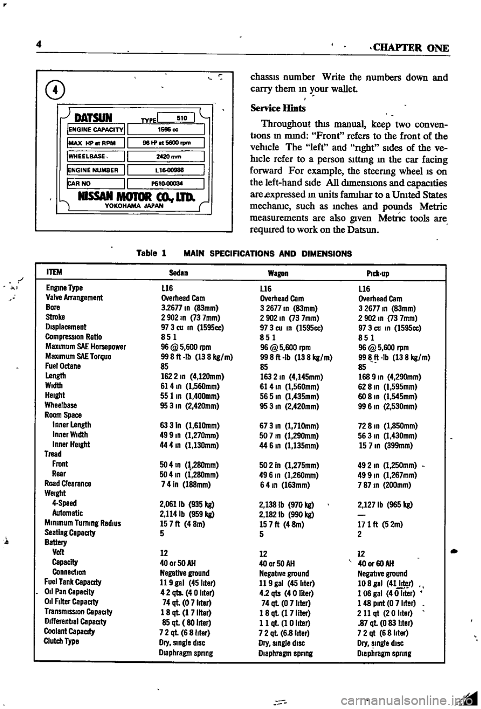
Table
1
MAIN
SPECIFICATIONS
AND
DIMENSIONS
r
ITEM
Sedan
Wagon
Plm
up
EnglDe
Type
L16
L16
L16
Valve
Arrangement
Overhead
Cam
Overhead
Cam
Overhead
Cam
Bore
3
26n
ID
83mm
3
2677
ID
83mm
3
2677
ID
83mm
Stroke
2902
ID
73
7mm
2
902
ID
73
7mm
2
902
In
73
7mm
Displacement
97
3
cu
ID
l595cc
97
3
cu
In
l595cc
97
3
cu
ID
1595cc
CompressIOn
Ratio
851
851
851
MaXimum
SAE
Hompower
96
@
5
600
rpm
96
@
5
600
rpm
96
@
5
600
rpm
MaXimum
SAE
Torque
998ft
Ib
138
kg
m
998ft
Ib
138
kg
m
9911
ft
Ib
138
kg
m
Fuel
Octane
85
85
85
Lengtb
1622
ID
4
12Omm
163
2
ID
4
I45mm
168
9
ID
4
290mm
Width
61
4
ID
l
560mm
61
4
ID
1
560mm
62
8
In
Cl
595mm
Height
55
lID
1
400mm
565
ID
Cl
435mm
60
8
ID
Cl
545mm
Wheelbase
95
3
ID
2
42Omm
95
3
ID
2
420mm
99
6
In
2
530mm
Room
Space
Inner
Length
63
3
In
1
61Omm
673
ID
1
710mm
72
8
ID
1
850mm
Inner
Width
499
ID
1
27Omm
507
ID
1
29Omm
563
In
1
430mm
Inner
Height
44
4
In
1
130mm
44
61D
1
135mm
15
7
ID
399mm
Tread
Front
50
4
ID
28Omm
502
In
1
275mm
492
In
1
250mm
Rear
504
In
1
280mm
496
In
Cl
260mm
499
ID
1
267mm
Road
Clearance
741n
l88mm
64
ID
l63mm
787
ID
200mm
Weight
4
Speed
2
0611b
935
kg
2
138
Ib
970
kg
2
127
Ib
965
kg
Automatic
2
114Ib
959
kg
2
182
Ib
990
kg
Minimum
Turning
RadiUS
157ft
48m
157ft
48m
171
ft
52m
Seating
Capaaty
5
5
2
Battery
Volt
12
12
12
Capacity
400rSOAH
400r50AH
40
or
60
AH
Connection
Negative
ground
Negative
ground
Negative
ground
Fuel
Tank
Capaaty
11
9
gal
45
liter
11
9
gal
45
liter
108
gal
41J
r
011
Pan
Capacity
42
qts
40
liter
4
2
qb
40
liter
1
06
gal
40
Iller
011
Filter
Capaaty
74
ql
07
liter
74
ql
0
7
liter
1
48
Pint
0
7
liter
Transmission
Capaaty
1
8
ql
1
7
liter
18
ql
1
7
Iller
2
11
qt
20
Iller
Dlflerenbal
Capaaty
85
ql
80
liter
11
ql
1
0
liter
87
ql
0
83
lIter
Coolant
Capaaty
7
2
ql
6
8
liter
7
2
ql
6
8
lIter
7
2
qt
6
8
Iller
Clutch
Type
Dry
Single
diSC
Dry
slDgle
diSC
Dry
slDgle
diSC
Draphragm
spnng
Diaphragm
spnng
Diaphragm
spnng
l
Page 27 of 252

22
CHAPTER
FOUR
CD
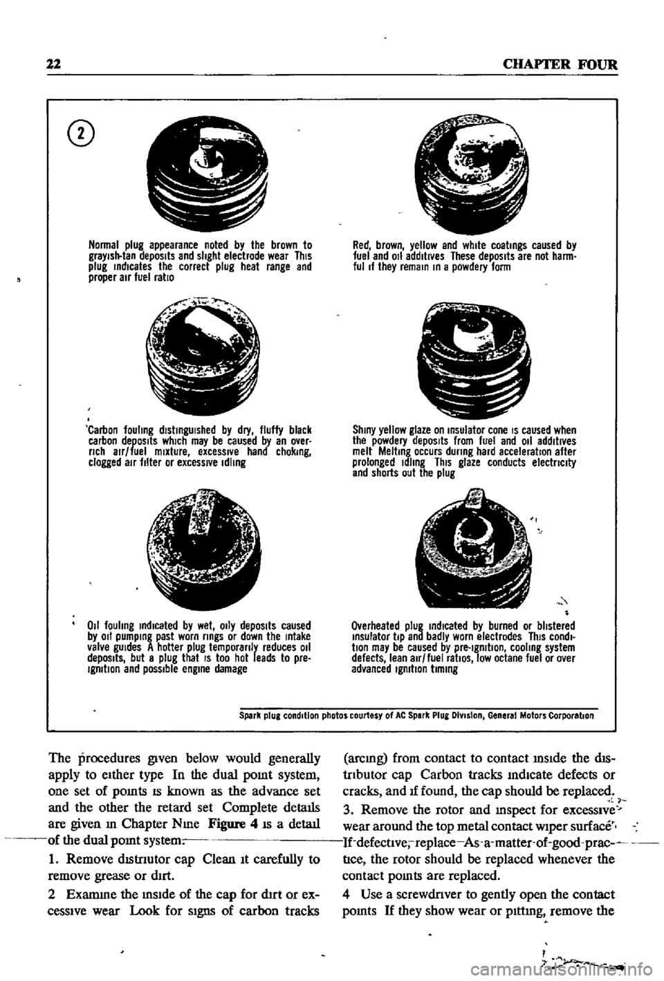
Normal
plug
appearance
noted
by
the
brown
to
graYish
tan
deposits
and
slight
electrode
wear
This
plug
rndlcates
the
correct
plug
heat
range
and
proper
air
fuel
ratio
f
j
l
Carbon
fouling
dlstrngUlshed
by
dry
fluffy
black
carbon
deposits
which
may
be
caused
by
an
over
nch
alr
fuel
mixture
excessIVe
hand
chokrng
clogged
air
filter
or
excessive
Idling
lJ
6
1
4i
Z
011
fouling
rndlcated
by
wet
OIly
depOSits
caused
by
011
pumprng
past
worn
rrngs
or
down
the
rntake
valve
gUides
A
hotter
plug
temporanly
reduces
011
depOSits
but
a
plug
that
IS
too
hot
leads
to
pre
IgmtlOn
and
possible
engrne
damage
Red
brown
yellow
and
white
coatrngs
caused
by
fuel
and
011
additives
These
depOSits
are
not
harm
ful
If
they
remarn
rn
a
powdery
form
C
I
Shrny
yellow
glaze
on
rnsulator
cone
IS
caused
when
the
powdery
depOSits
from
fuel
and
011
additives
melt
Meltrng
occurs
dunng
hard
acceleration
after
prolonged
Idling
This
glaze
conducts
electnclty
and
shorts
out
the
plug
Overheated
plug
rndlcated
by
burned
or
blistered
rnsulator
tip
and
badly
worn
electrodes
This
condl
bon
may
be
caused
by
pre
Igmtlon
cooling
system
defects
lean
air
fuel
ratiOS
low
octane
fuel
or
over
advanced
Igmbon
bmrng
Spark
plug
condition
photos
courtesy
of
At
Spark
Plug
DIvision
General
Motors
Corporation
The
procedures
given
below
would
generally
apply
to
eIther
type
In
the
dual
pomt
system
one
set
of
pomts
IS
known
as
the
advance
set
and
the
other
the
retard
set
Complete
details
are
given
m
Chapter
Nme
Figure
4
IS
a
detaIl
of
the
dual
pomt
system
1
Remove
dIStnutor
cap
Clean
It
carefully
to
remove
grease
or
dIrt
2
Examme
the
mSIde
of
the
cap
for
d1rt
or
ex
ceSSIve
wear
Look
for
SIgns
of
carbon
tracks
arcmg
from
contact
to
contact
mSIde
the
dIS
trIbutor
cap
Carbon
tracks
mdlcate
defects
or
cracks
and
If
found
the
cap
should
be
replaced
3
Remove
the
rotor
and
mspect
for
exceSSIve
wear
around
the
top
metal
contact
wiper
surface
If
defectlve
replace
As
a
matter
of
good
prac
nce
the
rotor
should
be
replaced
whenever
the
contact
pomts
are
replaced
4
Use
a
screwdriver
to
gently
open
the
contact
pomts
If
they
show
wear
or
plttmg
remove
the
I
7
r
Page 118 of 252

ENGINE
ELECI
RICAL
SYSTEM
113
i
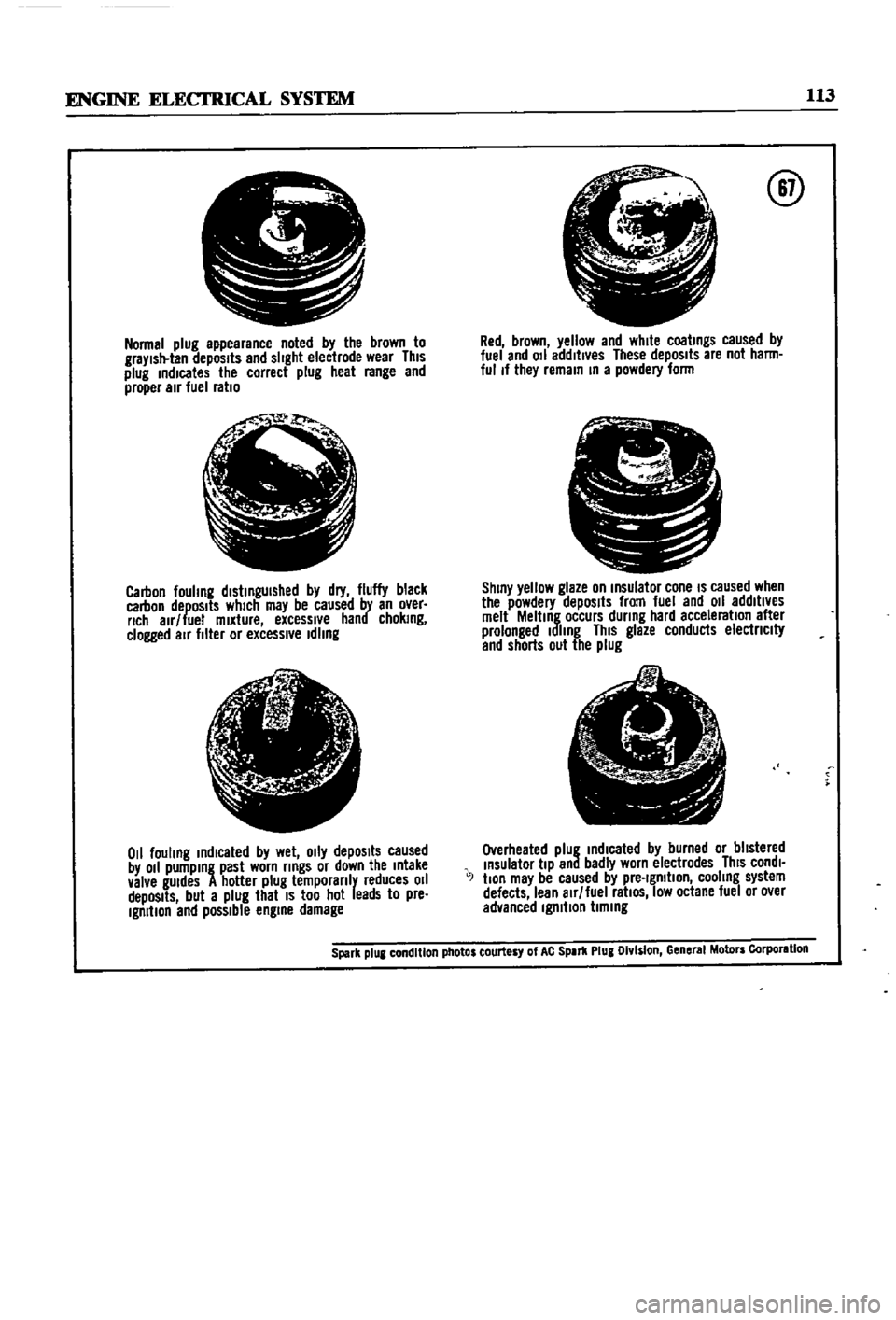
Normal
plug
appearance
noted
by
the
brown
to
graYlsll
lan
depOSits
and
slight
eleclrode
wear
This
plug
indicates
the
correct
plug
heal
range
and
proper
air
fuel
ratio
jI
Jo
t
Ql
i
Carbon
fouhng
distinguished
by
dry
fluffy
black
carbon
depOSits
which
may
be
caused
by
an
over
rich
alr
lue
mixture
excessive
hand
choking
clogged
air
filler
or
excessl
e
Idling
t
I
j
if
r
l
1
tfc
ji
0
1
fouling
indicated
by
wet
o
ly
depOSits
caused
by
011
pumping
past
worn
rings
or
down
the
Intake
valve
gUIdes
A
hotter
plug
temporanly
reduces
011
depOSits
but
a
plug
that
IS
too
hot
leads
to
pre
Ignition
end
possible
engine
damage
@
Red
brown
yellow
and
white
coatings
caused
by
luel
and
011
addltl
es
These
depOSits
are
not
harm
ful
If
they
remain
In
a
powdery
lorm
pr
11
L
J
J
S
C
ShinY
yellow
glaze
on
Insulalor
cone
IS
caused
when
the
powdery
depOSits
from
fuel
and
011
addltl
es
melt
Melting
occurs
during
hard
acceleration
alter
prolonged
Idling
This
glaze
conducts
electnclty
and
shorts
out
the
plug
e
1
A
I
A
I
7
Overheated
plug
indIcated
by
burned
or
blistered
Insulator
tiP
and
badly
worn
electrodes
ThiS
condl
J
tlon
may
be
caused
by
pre
Ignition
cooling
system
defects
lean
alr
luel
ratiOS
low
octane
luel
or
o
er
advanced
Ignition
timing
Spark
plUI
condition
photos
courtesy
of
AC
SPIr1l
Plug
Olv
s
on
Gene
MolDrs
Corporlllon