1968 DATSUN 510 oil level
[x] Cancel search: oil levelPage 11 of 252
CHAPTER
TWO
PERIODIC
MAINTENANCE
To
ensure
good
performance
dependability
and
safety
regular
penodlc
maintenance
is
necessary
TIns
chapter
outlInes
routine
and
penodlc
mamtenance
for
the
average
dnver
Under
heavy
usage
semcmg
mtervals
will
be
shortened
Regular
routme
mamtenance
will
help
aVOId
expensive
repaIrs
ROUTINE
CHECKS
The
followlDg
checks
should
be
performed
at
each
fuel
stop
1
Check
engme
oil
level
Top
up
as
requrred
2
Check
radiator
coolant
level
Top
up
as
re
qwred
3
Check
battery
electrolyte
The
battery
case
IS
marked
With
upper
hrmt
and
lower
lnmt
lInes
Level
should
be
maID
tamed
between
the
IIDes
4
Check
that
the
master
cylInder
brake
flwd
reservOir
level
IS
between
the
max
and
mm
lInes
marked
on
the
plastic
case
S
Check
the
plastic
clutch
cyhnder
reservoir
level
Level
should
be
between
the
max
and
mm
lInes
6
Check
the
windsh1eld
washer
flwd
reservoir
Top
up
as
required
7
Check
tire
pressures
when
the
tIres
are
cold
Front
and
rear
tire
pressures
should
be
24
pounds
under
normal
dnving
conditions
TIre
pressure
should
be
28
pounds
for
h1gh
speed
dnvmg
conditions
8
Check
the
engIne
for
general
conditIon
Check
for
leaky
or
cracked
hoses
and
loose
wmng
9
Check
condition
of
wmdshleld
wiper
blades
PERIODIC
CHECKS
Table
1
prOVIdes
penodIc
checks
and
main
tenance
that
should
be
performed
on
a
set
schedule
Table
2
gIves
recommended
lubncants
and
Table
3
specIfies
the
grades
of
oil
that
should
be
used
Procedures
for
performmg
the
semces
are
presented
ID
vanous
chapters
of
tlus
manual
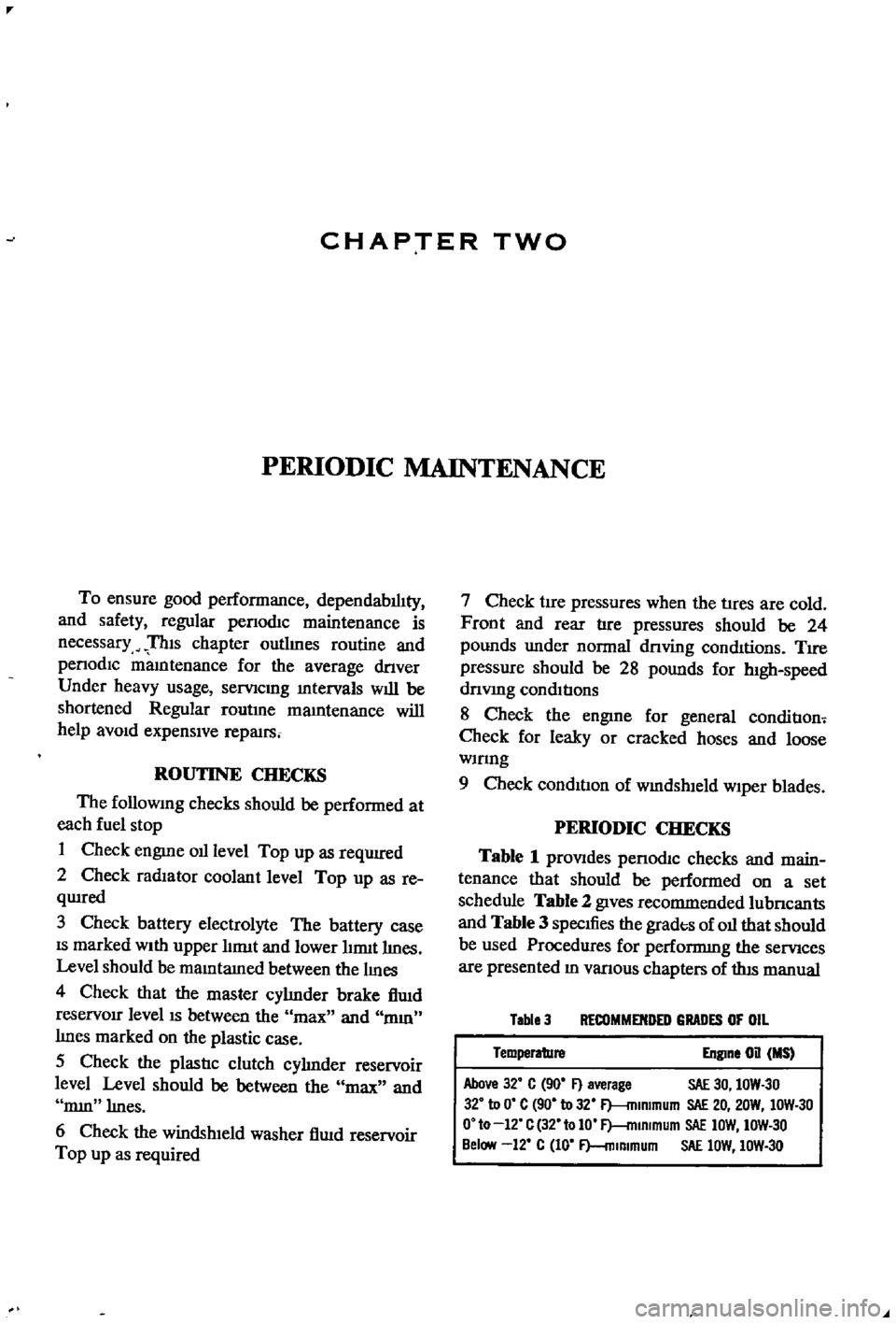
Table
3
RECOMMENDED
GRADES
OF
OIL
Temperature
Engine
on
MS
Above
32
C
90
F
average
SAE
30
IOW
30
32
to
0
C
90
to
32
F
mlmmum
SAE
20
20W
IOW
30
O
to
12
C
32
tolO
F
mlRlmum
SAE
IOW
IOW
30
Below
12
C
10
F
mlmmum
SAE
lOW
IOW
30
Page 18 of 252

TROUBLESHOOTING
13
trouble
may
also
be
worn
bearings
Remove
the
alternator
and
repair
ENGINE
These
procedures
assume
the
starter
cranks
the
engme
over
normally
If
not
refer
to
Starter
section
m
this
chapter
1
Engme
won
t
start
Could
be
caused
by
the
IgOltlon
or
fuel
problems
First
determine
If
high
voltage
to
spark
plug
occurs
To
do
thiS
dISconnect
one
of
the
spark
plug
wires
Hold
the
exposed
wrre
termlOal
y
to
Y2
lOch
from
ground
any
metal
in
engine
com
partment
With
an
msulated
screwdriver
Crank
the
engme
over
If
sparks
do
not
Jump
to
ground
or
the
sparks
are
very
weak
the
trouble
may
be
10
the
IgnitIOn
system
See
Ignition
System
Trou
bleshootmg
to
further
check
If
sparks
occur
properly
the
trouble
may
be
10
the
fuel
system
See
Fuel
System
Troubleshootmg
2
Engme
misses
steadily
Remove
one
spark
plug
wrre
at
a
tune
and
ground
the
wrre
If
engme
mISs
increases
that
cyhnder
was
work
109
properly
Reconnect
the
wire
and
check
the
others
When
a
wire
IS
dIs
connected
and
engme
miss
remams
the
same
that
cylinder
IS
not
finng
Check
spark
as
descnbed
10
Step
1
If
no
spark
occurs
for
one
cyhnder
only
check
dlStnbutor
cap
wrre
and
spark
plug
If
spark
occurs
prop
erly
check
compressIOn
and
mtake
maOlfold
vacuum
to
ISolate
the
trouble
3
Engme
misses
erratlcally
at
all
speeds
Interrmttent
trouble
can
be
difficult
to
find
It
could
be
ill
the
Ignition
system
exhaust
system
or
fuel
system
Follow
troubleshooting
proce
dures
for
these
systems
carefully
to
isolate
the
trouble
4
Engme
misses
at
Idle
only
Trouble
could
exist
anywhere
ill
IgOltlon
system
Follow
Ignition
TroubleshootlOg
procedure
care
fully
Trouble
could
also
eXist
10
the
carburetor
Idle
crrcult
Check
Idle
mIXture
adjustment
and
check
for
restnctions
m
the
idle
crrcUlt
5
Engme
misses
at
high
speed
only
Problems
could
be
ill
the
fuel
or
IgOltlon
systems
heck
accelerator
pump
operation
fuel
pump
dehvery
fuel
hnes
etc
as
descnbed
under
Fuel
System
Troubleshootillg
Also
check
spark
plugs
and
wrres
6
Low
performance
at
all
speeds
poor
acceleratIOn
Trouble
usually
ill
IgOltlon
or
fuel
system
Check
each
With
the
appropnate
troubleshooting
pro
cedure
7
ExceSSive
fuel
consumptIOn
Could
be
caused
by
a
Wide
variety
of
seemmgly
unrelated
factors
Check
for
clutch
shppage
brake
drag
defective
wheel
beanngs
or
poor
front
end
alignment
Check
IgOltlOn
system
and
fuel
system
8
011
pressure
lamp
does
not
light
when
IgmtlOn
switch
IS
on
Check
the
alternator
warning
lamp
If
it
ISn
t
on
either
go
to
Step
1
Chargmg
System
Trouble
shootlOg
If
only
the
oil
pressure
lamp
IS
off
open
the
englOe
compartment
hd
and
locate
the
oil
pressure
sender
on
the
block
near
the
oil
filter
Make
sure
the
wrre
is
connected
to
the
sender
and
makmg
good
contact
Pull
the
wrre
off
and
ground
it
If
the
lamp
hghts
replace
the
sender
If
the
lamp
does
not
light
replace
the
lamp
9
011
pressure
lamp
lights
or
flickers
when
engme
IS
runmng
Indicates
low
or
complete
loss
of
oil
pressure
Stop
the
englOe
unmedmtely
coast
to
a
stop
With
the
clutch
dISengaged
Tlus
may
simply
be
caused
by
a
low
oil
level
or
an
overheatmg
en
glOe
Check
the
oil
level
and
fan
belt
tensIOn
Check
for
a
shorted
oil
pressure
sender
with
an
ohmmeter
or
a
contlOulty
tester
Remove
and
clean
the
oil
dipstick
and
check
oil
level
and
condition
RepleOlsh
or
replace
the
oil
as
re
qurred
Listen
for
unusual
nOISes
mdlcatmg
dam
aged
beanngs
etc
Do
not
re
start
the
engine
until
you
know
why
the
hght
went
on
and
are
sure
that
the
problem
has
been
corrected
IGNITION
SYSTEM
This
procedure
assumes
the
battery
IS
ill
good
enough
condition
to
crank
the
engme
at
a
normal
rate
Page 26 of 252

ENGINE
AND
IGNITION
TUNE
UP
21
many
types
of
test
eqUipment
and
may
be
used
as
a
gUide
If
the
manufacturer
s
mstructioQs
are
not
aVailable
Connections
shown
in
Figure
1
are
as
follows
1
Voltmeter
a
PosItive
lead
to
resistor
side
of
COli
b
Negative
1
ead
to
ground
2
Tlmmg
Light
a
PosItive
lead
to
posItive
battery
termmal
b
Tngger
lead
to
number
1
spark
plug
c
Negative
lead
to
ground
3
Tachometer
a
PosItive
lead
to
dlstnbutor
Side
of
coil
b
Negative
lead
to
ground
4
Dwell
Meter
a
PosItive
lead
to
dlstnbutor
Side
of
COlI
b
Negative
lead
to
ground
BAlTERY
INSPECTION
AND
SERVICE
1
Check
the
level
of
the
electrolyte
m
battery
cells
If
necessary
replemsh
with
distilled
water
Do
not
overfill
2
Measure
the
speCific
gravity
of
the
battery
electrolyte
Refer
to
the
followmg
table
2
Use
the
proper
size
socket
and
wrench
to
remove
spark
plugs
from
the
cyhnder
head
Make
certam
that
the
gaskets
are
removed
from
the
spark
plug
holes
3
Wipe
off
the
msulator
With
a
clean
rag
to
remove
grease
and
dirt
4
Carefully
mspect
the
msulator
and
body
of
each
plug
for
signs
of
cracks
or
chips
Replace
If
faulty
5
Inspect
spark
plug
threads
and
electrodes
for
damage
or
excessive
wear
Replace
as
requrred
Figure
2
shows
the
cond1t
J
on
of
normal
and
de
fectIVe
spark
plugs
along
with
an
explanation
of
the
causes
of
the
abnormal
conditions
6
If
the
spark
plugs
are
still
serviceable
clean
them
thoroughly
With
a
stiff
brush
or
preferably
With
a
sand
blasting
type
of
cleaner
7
File
the
center
electrode
so
that
It
has
a
fiat
surface
8
File
the
surfaces
of
the
outer
electrode
so
that
all
surfaces
are
fiat
and
smooth
9
Usmg
a
feeler
gauge
adjust
clearance
be
tween
the
electrodes
to
0
031
to
0
035
m
0
8
to
0
9mm
as
shown
m
Figure
3
Full
Charge
Value
CD
68
degrees
F
PermiSSIble
Value
20
degrees
C
3
Frigid
chmates
Tropical
chmates
Other
climates
Over
1
22
Over
118
Over
1
20
128
123
126
3
Clean
top
of
battery
and
termmals
With
a
solutIOn
of
bakmg
soda
and
water
Rmse
off
and
dry
thoroughly
Top
of
battery
must
be
clean
to
prevent
current
leakage
between
termmal
and
from
pOSitive
termmal
to
hold
down
clamp
Pro
longed
accumulatIOn
of
aCid
and
dirt
on
top
of
battery
may
cause
blIstenng
of
the
matenal
cov
enng
on
the
connector
straps
and
detenoration
of
the
straps
themselves
4
Tighten
the
cable
connectors
to
the
termmal
securely
5
Coat
the
termmals
lIghtly
With
petrolatum
to
protect
them
from
corrosion
SPARK
PLUGS
INSPECTION
AND
SERVICE
1
Remove
spark
plug
WIres
Mark
them
to
fi
sure
correct
replacement
J
J
I
I
j
j
10
Remstall
spark
plugs
Make
certam
to
use
a
new
gasket
for
each
plug
Use
a
torque
wrench
to
tighten
spark
plugs
from
11
0
to
150
ft
lb
1
5
to
2
0
kg
m
11
Remstall
WIres
DISTRIBUTOR
INSPECTION
AND
SERVICE
Dependmg
on
the
model
year
velucles
have
a
smgle
pomt
or
a
dual
pomt
dlstnbutor
system
Page 29 of 252

P
r
OVll
t
ate
I
l
h
l
JlA
ye
I
o
ctg
fI
O
0
I
d
1e
d
c
Ji
uo
JJ
cb
c
s
rlr
I
l
4
c
1
2
24
CHAPTER
FOUR
block
and
should
be
used
as
the
reference
point
m
II
1akmg
adjustments
6
With
a
piece
of
white
chalk
mark
a
hne
down
the
center
of
the
pomter
and
mark
the
timing
groove
on
the
crankshaft
pulley
which
IS
to
be
used
m
tImmg
the
engine
SpecIficatIon
for
tun
ing
reqUIres
trlhmg
at
10
degrees
before
top
dead
center
wluch
would
be
the
fourth
mark
from
the
left
end
of
the
row
of
marks
7
Loosen
the
hold
down
bolt
at
the
base
of
the
dlstnbutor
8
Locate
the
slow
speed
1
Ile
adjustIng
screw
on
the
carburetor
so
that
Ile
speed
can
be
adjusted
whIle
runnmg
Also
locate
throttle
adJustmg
screw
9
Start
engme
and
adjust
speed
With
the
adJust
ing
screws
to
the
readmgs
below
Smgle
pomt
dIStributor
600
rpm
Dual
pomt
trlbutor
700
rpm
10
Alternate
adjustment
of
the
two
screws
untIl
the
smoothest
Idle
at
the
proper
speed
IS
achieved
11
Pomt
the
tlIrung
lIght
at
the
stationary
pomter
When
the
lIght
flashes
the
timmg
mark
n
the
crankshaft
pulley
should
hne
up
With
the
mark
on
the
stationary
pomter
If
It
does
not
exactly
Ime
up
rotate
the
dlstnbutor
gradually
untIl
the
marks
align
mdlcatlng
correct
timmg
12
Shut
off
the
engme
remove
the
tmung
lIght
and
tachometer
tighten
the
hold
down
bolt
on
the
dlStnbutor
and
connect
the
vacuum
advance
hne
to
the
tli
tnbutor
IGNITION
TIMING
IDLE
SPEED
IDLE
MIXTURE
DUAL
POINT
DISTRIBUTOR
ONLY
The
followmg
applies
to
velucles
With
dual
pomt
distributor
and
an
exhaust
emission
con
trol
deVice
If
these
procedures
are
followed
ha
ul
exhaust
emisSion
should
be
below
the
maximum
allowable
level
1
Locate
the
Idle
and
throttle
adJustmg
screws
on
the
carburetor
2
Warm
up
the
engine
thoroughly
3
Connect
tachometer
and
tmung
light
4
Set
the
Id
le
speed
at
700
rpm
With
the
Idle
adjust
screw
5
Adjust
IgnltJ
on
tuning
at
10
degrees
before
top
dead
center
6
Increase
the
speed
of
the
engme
to
2
000
rpm
With
the
accelerator
or
throttle
hnkage
and
hold
for
about
15
seconds
7
Return
to
Idle
for
one
mmute
8
Set
the
engme
to
best
Idle
at
750
rpm
770
rpm
for
automatJ
c
transIDlsslOn
With
the
Idle
and
throttle
adJustmg
screws
9
Re
uce
engme
speed
at
700
rpm
720
rpm
for
automatic
transmission
by
turnmg
the
Idle
adJustmg
screw
clockWise
for
a
leaner
IlliXture
10
Connect
a
wife
lead
between
the
advance
ami
retard
Side
tenrunals
See
Figure
4
Speed
should
drop
from
100
to
150
rpm
11
Check
IgIl1tIon
tmung
With
tImmg
light
It
should
now
be
at
top
d
ad
center
12
If
the
tlmmg
IS
nSJt
correct
stop
the
engme
and
adjust
the
retarded
breaker
pomt
13
Start
the
engme
and
reclieck
ili
tmung
If
l
incorrect
reset
the
retarded
breaker
pomt
until
it
IS
correct
Repeat
s
nece
s
14
Disconnect
the
wife
bet
reen
the
advance
and
retard
termmals
15
Recheck
tmung
It
should
be
10
degrees
before
top
dead
center
16
If
mcorrect
repeat
the
above
procedures
un
tIl
satIsfactory
17
T
he
Idle
speed
of
automatic
transnllsslOn
vehicles
should
be
about
575
rpm
With
the
gear
j
selector
m
the
dhve
poSltlon
c
t
DWELL
ANGLE
SETIING
1
Connect
the
dwell
angle
meter
2
PLoJust
dwell
angle
to
49
to
55
degrees
OMPRESSION
TEST
I
A
compressIOn
test
IS
performed
to
check
for
worn
piston
nngs
or
to
detect
the
cause
of
a
low
speed
miss
Before
undertaking
the
test
el
llmate
the
pOSSibility
of
sticky
valves
by
usmg
one
of
the
oil
additives
deSigned
for
the
purpose
With
valves
free
test
compressIOn
as
follows
1
Run
the
engme
for
15
to
20
mmutes
untIl
normal
operating
temperatures
are
obtained
2
Shut
off
engme
remove
arr
cleaner
and
Page 31 of 252
26
CHAPTER
FOUR
2
Check
all
belts
hoses
and
fuellmes
Replace
If
reqUIred
Check
the
tensIon
of
the
belts
for
the
au
pump
and
the
alternator
Adjust
as
re
qUIred
Normal
deflection
of
the
belts
when
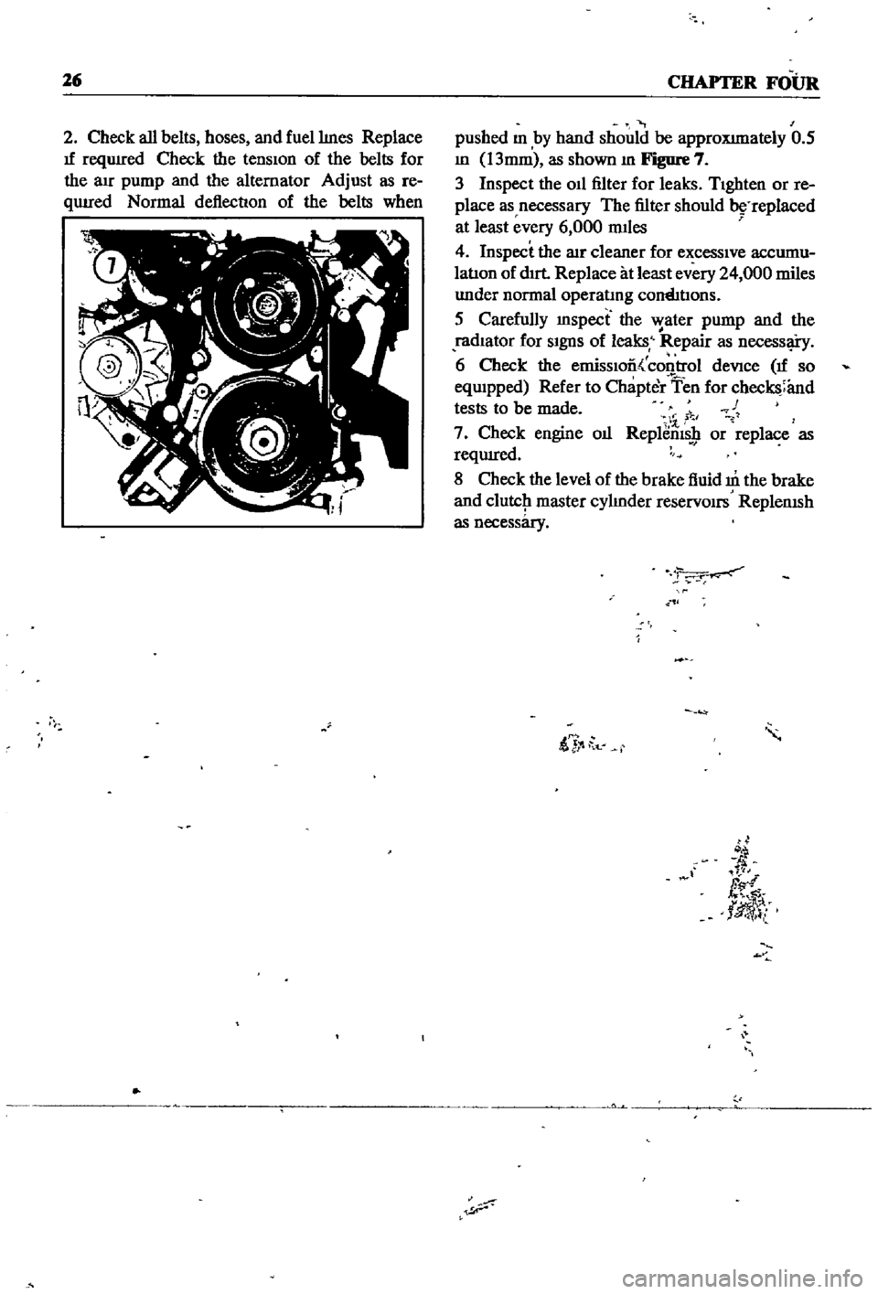
pushed
m
by
hand
should
be
approXImately
0
5
m
13mm
as
shown
m
Figure
7
3
Inspect
the
011
filter
for
leaks
TIghten
or
re
place
as
necessary
The
filter
should
replaced
at
least
every
6
000
mIles
4
Inspect
the
lIlr
cleaner
for
excessIve
accumu
latIon
of
dIrt
Replace
at
least
every
24
000
miles
under
normal
operatmg
cornhtIons
5
Carefully
mspect
the
water
pump
and
the
radIator
for
SIgnS
of
leaks
Repair
as
necessl
i
y
6
Check
the
emissIoo
control
deVice
If
so
eqwpped
Refer
to
Chapter
Ten
for
checks
and
tests
to
be
made
c
1
7
Check
engine
oIl
Replems
9
or
replace
as
reqUIred
8
Check
the
level
of
the
brake
fluid
m
the
brake
and
clutcJ1
master
cylmder
reservOirs
ReplenISh
as
necessary
ii
t
d
fl
tlJ
l
Page 38 of 252
4l
4111a
78
mml
la78mml
42
4
42
4OIla50mml
t
4544
i
35
45
lIq
D
1
43
45
44
6
1i
45
43
42
41
45
44
46
46
47
8
78mml
I
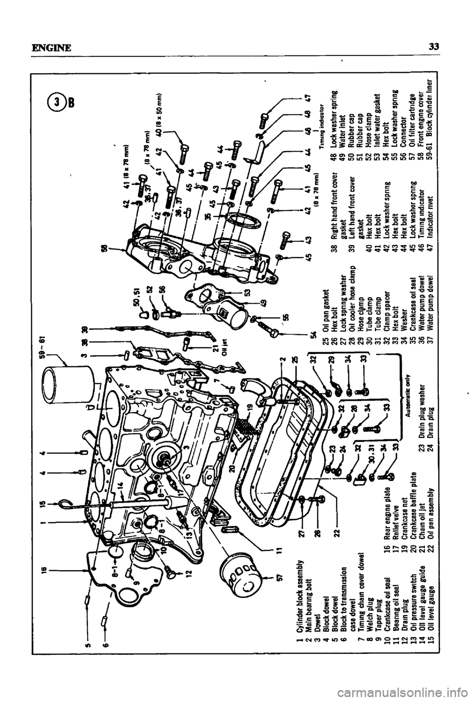
Tlmmg
Indicator
48
lock
washer
spring
49
Water
Inlet
50
Rubber
cap
51
Rubber
cap
52
Hosa
clamp
53
Inlet
watar
gasket
54
Hex
bolt
55
lock
washer
spring
56
Connector
57
011
filter
cartndge
58
front
engme
cover
59
61
Bloel
cyllndelllner
18
15
58
57
1
Cylinder
block
assembly
2
Main
beanng
bolt
3
Dowel
4
Block
dowel
5
Block
dowel
6
Block
to
transmIssIon
case
dowel
7
Tlmmg
chaIn
covar
dowel
8
Welch
plug
9
Taper
plug
10
Crankcase
011
seal
11
Bearing
011
seal
12
Drain
plug
13
011
pressure
sWitch
14
011
level
gauge
guide
15
Oll
evel
gauga
r1
26
54
25
011
pan
gasket
26
Hax
bolt
27
lock
Sprl
ng
washer
28
011
cooler
hose
clamp
29
Hose
cl
mp
30
Tube
clamp
31
Tube
clamp
32
Clamp
spacer
33
Hex
bolt
34
Washer
35
Crankcase
011
seel
36
Waler
pump
dowel
37
Water
pump
dowel
38
RIght
hand
front
caver
gasket
39
left
hand
front
cover
gasket
40
Hex
bolt
41
Hex
bolt
42
lock
washer
spnng
43
Hex
bolt
44
Hex
bolt
45
Lock
washer
spring
46
Tlmmg
Indicator
47
IndIcator
rivet
22
16
23
Drain
plug
washer
24
Dram
plug
e
l
lIlI
1M
1M
Page 152 of 252
CLUTCH
TRANSMISSION
AND
DRIVESHAFI
147
SERVICE
DATA
AND
SPECIFICATIONS
Table
3
gives
the
service
data
and
specIfica
tIons
for
the
dnveshaft
AUTOMATIC
TRANSMISSION
CHECKS
AND
ADJUSTMENTS
Whlle
removal
and
repair
of
the
automatic
transmisSIOn
IS
not
recommended
the
follo
VlIlg
checks
and
adjustments
should
help
prevent
costly
repatrs
Transmission
Oil
Check
Check
the
automatIc
transmission
oil
level
at
least
every
3
000
mlles
Replemsh
With
hIgh
qualIty
automatIc
transmISSIon
flUId
as
reqUIred
Be
careful
not
to
overfill
as
damage
to
the
seals
can
result
To
check
the
011
level
proceed
as
follows
1
Start
the
engme
and
nm
it
untIl
normal
oper
atrng
temperature
IS
reached
2
Apply
brakes
and
move
the
transmission
shut
lever
through
all
drive
pOSItions
and
place
lever
In
park
position
3
WIth
engme
running
remove
tranSmISSIon
dIp
StIck
clean
It
WIth
a
lInt
free
cloth
or
paper
and
return
it
to
the
transmission
4
Remove
dIp
stIck
agam
and
examine
level
on
dIp
stIck
gauge
It
should
be
between
the
low
and
full
marks
Replenish
as
necessary
5
VIsually
InSpect
the
color
and
condItIon
of
the
OIl
on
the
dIp
stIck
Normal
color
of
the
OIl
IS
red
If
the
color
IS
abnormal
dram
and
re
place
If
the
011
has
detenorated
to
a
vamlsh
lIke
qualIty
It
may
cause
the
control
valve
to
stIck
Blackened
oil
may
mdlcate
a
burned
clutch
or
brake
band
6
Should
the
above
condItIons
exist
refer
mamtenance
to
a
transmISSIon
specIalIst
Transmission
Oil
Leakage
Check
011
leakage
may
occur
at
the
Junction
of
the
transmissIon
and
rear
extensIon
011
tube
con
nectors
011
pan
OIl
pressure
mspectIon
holes
downshIft
solenoid
or
breather
pipe
Abnormal
OIl
usage
usually
mdlcates
leaks
that
should
be
stopped
before
severe
damage
IS
done
To
mspect
for
011
leaks
proceed
as
follows
1
LIft
car
up
on
hOISt
or
Jack
up
and
place
on
stands
2
Clean
outsIde
of
transmISSIon
case
With
cleanIng
solvent
to
remove
dIrt
and
011
accumu
latIons
3
Start
engme
and
nm
untIl
operating
temper
ature
is
reached
4
ShIft
gear
lever
to
dnve
to
Increase
011
pres
sure
and
CIrculatIon
WIthin
tranSmISsion
5
Inspect
pOInts
mentIoned
above
for
SIgnS
of
leakage
Leakage
of
transrmSSIOn
011
IS
dIStrnC
tIve
by
its
reddISh
color
6
If
leaks
are
detected
refer
servIce
and
reparr
to
qualIfied
transrmssion
specialISt
Kick
down
Switch
and
Downshift
Solenoid
Checks
and
Adjustment
When
ktck
down
operatIon
IS
not
correct
or
the
speed
changmg
pomt
IS
too
high
check
the
klck
down
SWItch
downshIft
solenOId
and
the
wlDng
between
them
Figure
45
shows
the
loca
tIOn
of
these
parts
To
check
operatIon
proceed
as
follows
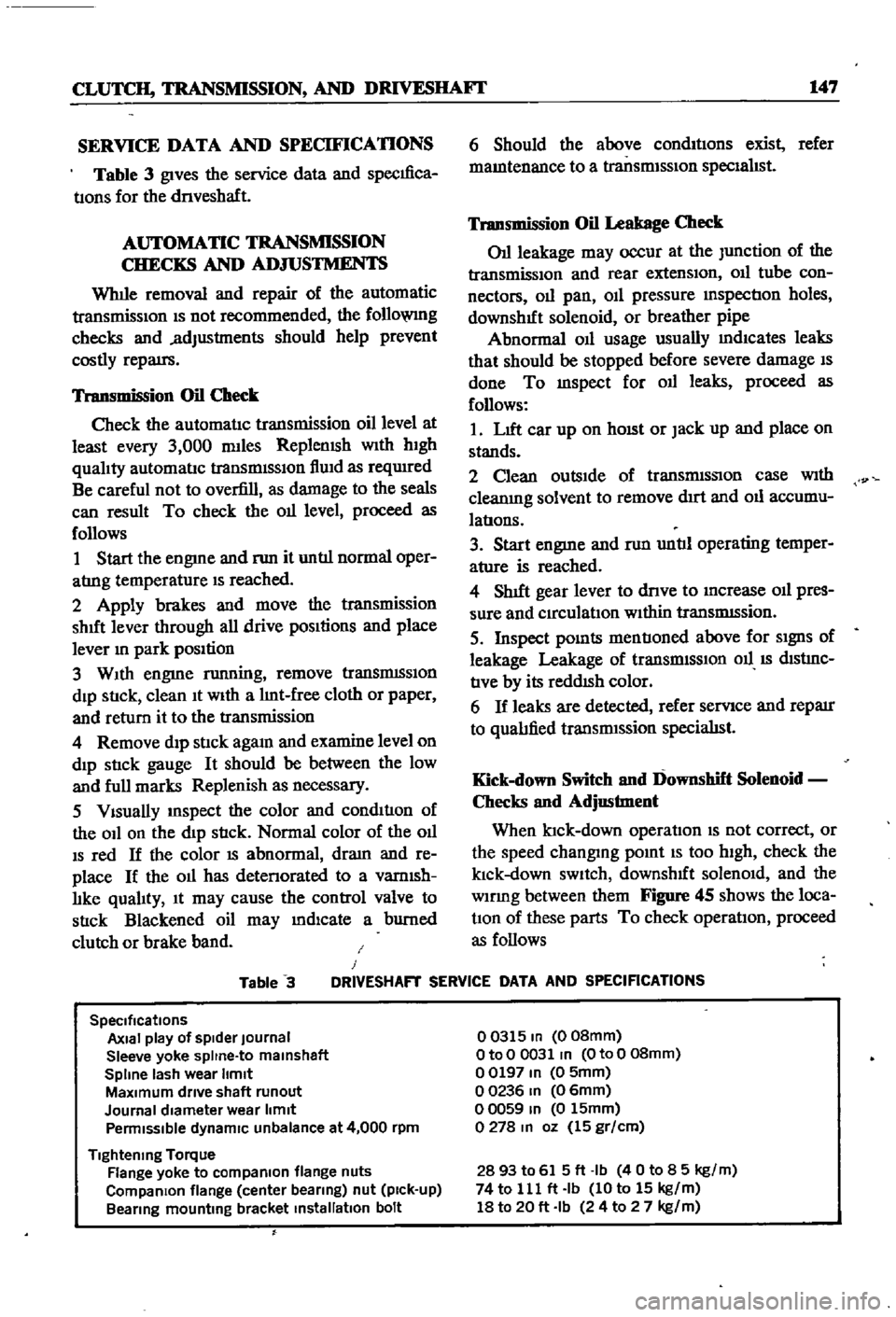
Table
3
J
DRIVESHAFT
SERVICE
DATA
AND
SPECIFICATIONS
SpeCifications
Axial
play
of
spider
Journal
Sleeve
yoke
spltne
to
malnshaft
Spline
lash
wear
Itmlt
MaXimum
drive
shaft
runout
Journal
diameter
wear
limit
Penmlsslble
dynamiC
unbalance
at
4
000
rpm
Tightening
Torque
Flange
yoke
to
compaRlon
flange
nuts
CompaRlon
flange
center
bearing
nut
pick
up
Bearing
mounting
bracket
installation
bolt
00315
In
008mm
OtoO
0031
In
OtoO
08mm
00197
In
0
5mm
00236
In
06mm
00059
In
0
15mm
0278
In
oz
15
gr
cm
2893
to
615ft
Ib
40
to
8
5
kg
m
74
to
111
ft
Ib
10
to
15
kg
m
18
to
20
ft
Ib
24
to
2
7
kg
m
Page 242 of 252
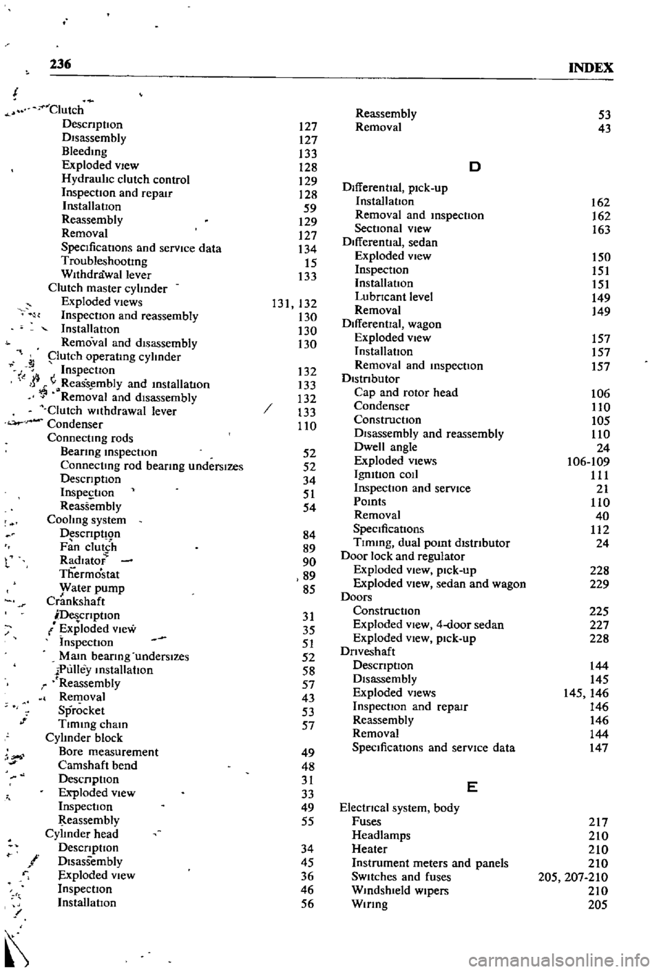
236
INDEX
Clutch
DescnptIon
DIsassembly
Bleedmg
Exploded
vIew
Hydraulic
clutch
control
InspectIOn
and
repair
InstallatIOn
Reassembly
Removal
SpecificatIons
and
service
data
TroubleshootIng
Withdrawal
lever
Clutch
master
cylinder
Exploded
views
InspectIon
and
reassembly
InstallatIOn
Removal
and
disassembly
putch
operatmg
cylinder
J
Inspection
I
jj
ReaSs
mbly
and
mslallatlOn
Removal
and
disassembly
Clutch
wllhdrawal
lever
Condenser
Connectmg
rods
Beanng
mspectIon
Connectmg
rod
bearmg
underslzes
DescrIptIOn
InspestIon
Reassembly
Cooling
system
D
scrIpt
Qn
Fan
clutch
Radlato
Thermostat
yvater
pump
Crankshaft
DescrIptIon
Exploded
View
Inspection
Mam
bearIng
underslzes
iPulley
mstallahon
r
Reassembly
Removal
Sprocket
Tlmmg
cham
Cylinder
block
Bore
measurement
Camshaft
bend
DesCrIpllOn
Exploded
view
InspectIOn
eassembly
Cylinder
head
DescrIptIon
f
DIsassembly
r
Exploded
View
InspectIOn
InstallatIOn
l
or
1
Reassembly
127
Removal
127
133
128
D
129
DifferentIal
pick
up
128
59
InstallatIon
129
Removal
and
mspecllOn
127
SectIOnal
view
134
Differential
sedan
15
Exploded
view
133
Inspection
InstallatIOn
131
132
LubrIcant
level
130
Removal
130
DifferentIal
wagon
130
Exploded
view
InstallatIon
132
Removal
and
mspecllon
133
DistrIbutor
132
Cap
and
rotor
head
133
Condenser
110
ConstructIon
DIsassembly
and
reassembly
52
Dwell
angle
52
Exploded
Views
34
IgmtIon
coIl
51
Inspection
and
service
54
Pomts
Removal
84
SpeCificatIons
89
Tlmmg
dual
pomt
distrIbutor
90
Door
lock
and
regulator
89
Exploded
view
pick
up
85
Exploded
View
sedan
and
wagon
Doors
31
Construction
35
Exploded
view
4
door
sedan
51
Exploded
vIew
pick
up
52
DrIveshaft
58
DescrIptIOn
57
Disassembly
43
Exploded
Views
53
InspectIon
and
repaIr
57
Reassembly
Removal
49
SpeCificatIons
and
service
data
48
31
E
33
49
ElectrIcal
system
body
55
Fuses
Headlamps
34
Heater
45
Instrument
meters
and
panels
36
SWitches
and
fuses
46
Wmdshleld
wipers
56
Wmng
53
43
162
162
163
150
151
151
149
149
157
157
157
106
110
105
110
24
106
109
111
21
110
40
112
24
228
229
225
227
228
144
145
145
146
146
146
144
147
217
210
210
210
205
207
210
210
205