1968 DATSUN 510 fuel cap release
[x] Cancel search: fuel cap releasePage 20 of 252

TROUBLESHOOTING
15
5
Stumbling
when
acceleratmg
from
Idle
Check
accelerator
pump
diaphragm
and
Idle
speed
adjustment
6
Engine
mISses
at
hIgh
speed
or
lacks
power
This
mdlcates
pOSSible
fuel
starvatIon
Check
fuel
pump
pressure
and
capacIty
Clean
main
Jet
and
float
needle
valve
7
Black
exhaust
smoke
Black
exhaust
smoke
means
a
badly
ovemch
nuxture
Check
Idle
mIXture
and
Idle
speed
ad
Justment
Check
for
excessive
fuel
pump
pres
sure
or
blocked
return
hne
from
carburetor
to
fuel
tank
Check
for
leaky
float
or
worn
needle
valve
8
ExceSSIve
fuel
consumptIOn
ThIS
may
be
another
mdIcatIon
of
an
ovemch
fuel
mixture
Check
that
automatIc
choke
oper
ates
If
so
eqUIpped
or
that
the
manual
choke
contraIlS
not
being
left
out
Check
Idle
mIXture
and
Idle
speed
Check
for
excessIve
fuel
pump
pressure
leaky
float
or
worn
needle
valve
Make
certam
that
jets
are
the
proper
SIZe
Fuel
Pump
Pressure
Testing
1
Install
a
T
fittmg
m
the
fuel
hue
close
to
the
carburetor
2
Connect
a
fuel
pressure
gauge
to
the
fittmg
WIth
a
short
tube
3
Check
fuel
pump
pressure
as
described
in
the
Fuel
System
chapter
EXHAUST
EMISSION
CONTROL
The
followmg
symptoms
as
ume
you
have
ad
justed
the
Ignition
and
carburetor
to
specdicatIon
and
that
you
have
checked
the
results
on
an
accurate
exhaust
gas
anajyzer
1
CO
content
too
low
Make
sure
Idle
speed
IS
not
too
low
Check
Idle
mIXture
adjustment
too
lean
Check
carbu
retor
Jets
and
channels
Clean
and
or
replace
as
necessary
Check
engme
condition
With
a
com
pressIOn
and
vacuum
test
2
CO
content
too
hIgh
Check
Idle
mixture
adjustment
too
nch
Check
for
dIrty
air
cleaner
and
defectIve
automatIc
choke
If
so
equipped
Check
carburetor
Jets
and
channels
Clean
and
or
replace
as
necessary
Check
engme
condItIon
WIth
compression
and
vacuum
test
3
Hydrocarbon
level
too
hIgh
Check
that
Idle
speed
and
mIXture
adjustments
are
to
specIfication
Check
spark
plug
condItIon
and
gap
Check
breaker
pomts
Check
IgnItIon
tnumg
too
early
Check
mtake
mamfold
for
leaks
Check
valve
clearance
too
small
Check
condItIon
of
valves
With
compressIOn
test
MANUAL
CLUTCH
1
SlIppage
ThiS
is
most
noticeable
when
acceleratIng
m
a
hIgh
gear
at
relatIvely
slow
speed
To
check
slip
page
park
the
car
on
a
level
surface
WIth
the
handbrake
set
ShIft
to
2nd
gear
and
release
the
clutch
as
If
drlVing
off
If
the
clutch
is
good
the
engme
will
slow
and
stall
If
the
clutch
shps
con
tInued
engme
speed
will
gIve
It
away
CAUTION
ThIS
IS
a
severe
test
Perform
only
when
slippage
IS
suspected
not
penodlcally
Shppage
results
from
IDSufliclent
clutch
pedal
free
play
all
or
grease
on
the
clutch
disc
worn
pressure
plate
or
weak
sprmgs
Also
check
for
bIndIng
m
the
clutch
cable
and
lever
arm
which
may
prevent
full
engagement
2
Drag
or
failure
to
release
ThIS
problem
usually
causes
dIfficult
shIftIng
and
gear
clash
espeCially
when
downshIftmg
The
causes
may
be
excessive
clutch
pedal
free
play
warped
or
bent
pressure
plate
or
clutch
dISC
ex
cessive
clutch
cable
guide
sag
and
broken
or
loose
clutch
lmings
Check
conditIOn
of
mam
shaft
splines
3
Chatter
or
grabbing
A
number
of
thmgs
can
cause
tIns
Check
cable
gUIde
sag
and
tIghtness
of
transnusslOn
to
frame
and
engme
to
transmlSslon
mountIng
bolts
Check
for
worn
or
mISaligned
pressure
plate
and
misalIgned
release
plate
4
Other
nOIses
NOISe
usually
mdlcates
a
dry
or
defective
release
bearIng
Check
the
beanng
and
replace
If
neces
Page 59 of 252

54
CHAP1ER
SIX
2
Set
the
valve
spnng
seat
m
position
on
the
top
of
the
block
and
over
the
valve
stem
3
Place
the
oil
seal
over
the
valve
stem
4
Place
the
mner
and
outer
valve
spnngs
over
the
valve
stem
S
Place
the
spnng
retamer
over
the
springs
compress
spnngs
With
spring
compressor
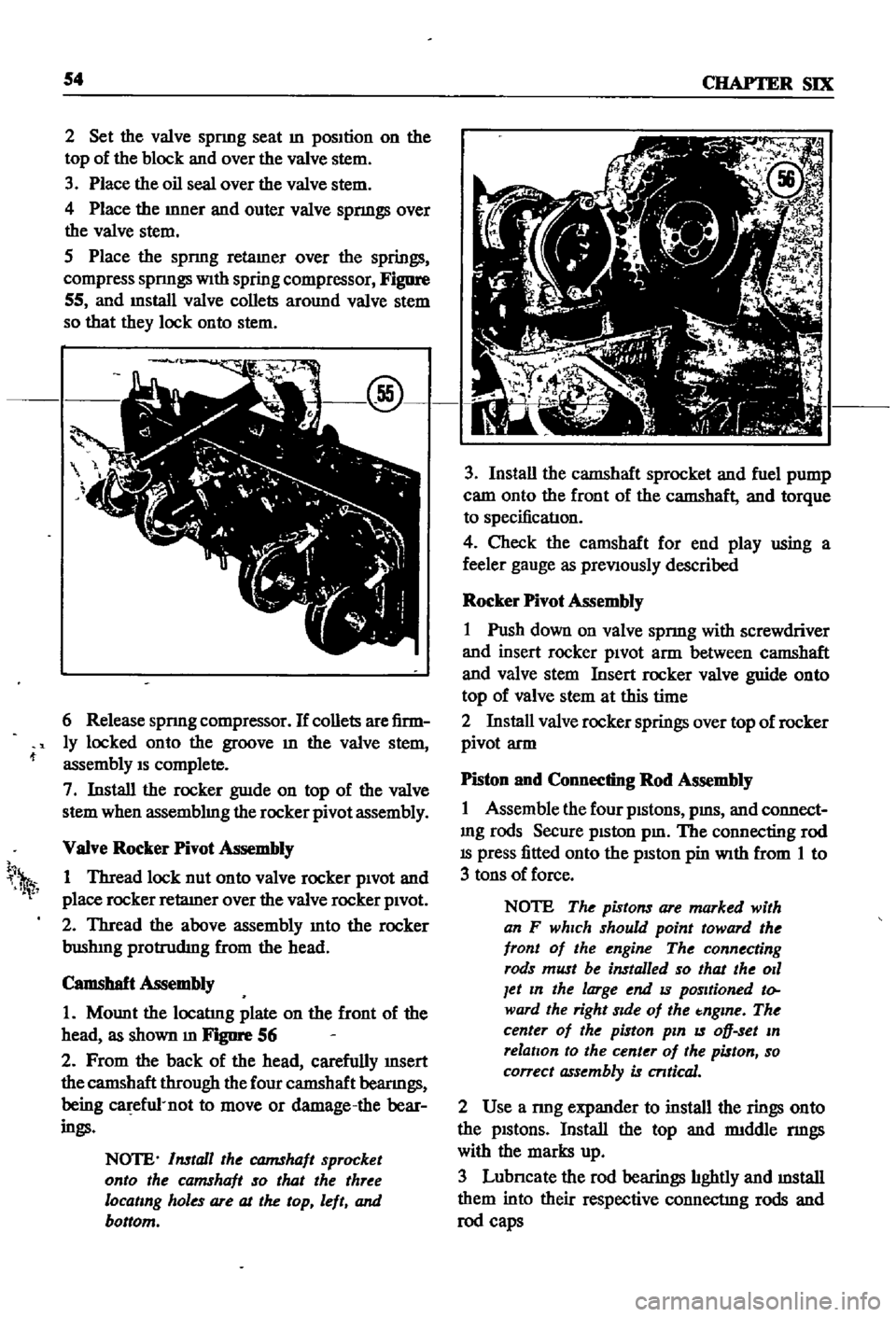
Figure
55
and
mstall
valve
collets
around
valve
stem
so
that
they
lock
onto
stem
6
Release
spnng
compressor
If
collets
are
firm
ly
locked
onto
the
groove
m
the
valve
stem
assembly
IS
complete
7
Install
the
rocker
guIde
on
top
of
the
valve
stem
when
assemblmg
the
rocker
pivot
assembly
VaIve
Rocker
Pivot
Assembly
1
Thread
lock
nut
onto
valve
rocker
pivOt
and
place
rocker
retaIner
over
the
valve
rocker
pivOt
2
Thread
the
above
assembly
mto
the
rocker
bushIng
protrudIng
from
the
head
Camshaft
Assembly
1
Mount
the
locatIng
plate
on
the
front
of
the
head
as
shown
m
FJgIlI
1
56
2
From
the
back
of
the
head
carefully
InSert
the
camshaft
through
the
four
camshaft
beanngs
being
ca
efu1
not
to
move
or
damage
the
bear
ings
NOTE
Install
the
CQJ7IShaft
sprocket
onto
the
camshaft
so
that
the
three
locating
holes
are
at
the
top
left
and
bottom
h
1
3
Install
the
camshaft
sprocket
and
fuel
pump
cam
onto
the
front
of
the
camshaft
and
torque
to
specificatIon
4
Check
the
camshaft
for
end
play
using
a
feeler
gauge
as
preViously
described
Rocker
Pivot
Assembly
1
Push
down
on
valve
spnng
with
screwdriver
and
insert
rocker
piVOt
arm
between
camshaft
and
valve
stem
Insert
rocker
valve
guide
onto
top
of
valve
stem
at
this
time
2
Install
valve
rocker
springs
over
top
of
rocker
pivot
arm
Piston
and
Connecting
Rod
Assembly
1
Assemble
the
four
pistons
pms
and
connect
mg
rods
Secure
piston
pm
The
connecting
rod
IS
press
fitted
onto
the
pISton
pin
With
from
1
to
3
tons
of
force
NOTE
The
pistons
are
marked
with
an
F
which
should
point
toward
the
front
of
the
engine
The
connecting
rods
must
be
installed
so
that
the
011
Jet
In
the
large
end
IS
positioned
to
ward
the
right
Side
of
the
tnglne
The
center
of
the
piston
pin
IS
oD
set
In
relation
to
the
center
of
the
piston
so
correct
assembly
is
cntical
2
Use
a
nng
expander
to
install
the
rings
onto
the
pistons
Install
the
top
and
rmddle
nngs
with
the
marks
up
3
Lubncate
the
rod
bearings
hghtly
and
mstall
them
into
their
respective
connectIng
rods
and
rod
caps
Page 64 of 252

ENGINE
59
2
Coat
the
pan
gasket
on
both
sides
With
gasket
compound
and
attach
the
oil
pan
to
the
cyhnder
block
Torque
as
specIfied
Manifold
and
Carburetor
Installation
1
Install
the
mtake
and
exhaust
manIfolds
WIth
associated
gasket
to
the
cylmder
head
2
Mount
the
carburetor
and
gasket
to
the
mtake
manIfold
2
Adjust
all
mtake
and
exhaust
valves
to
the
specIfied
clearance
for
a
cold
engme
Clutch
Assembly
Installation
CAUTION
Take
extreme
care
not
to
get
grease
or
011
on
the
clutch
or
flywheel
frlc
hon
contact
surfaces
1
Place
the
clutch
disc
assembly
on
the
flywheel
With
the
longer
chamfered
splmed
end
of
the
dISC
toward
the
transmISSion
2
Visually
align
or
use
a
dummy
splmed
dnve
shaft
to
ahgn
the
diSC
assembly
With
the
flywheel
pilot
beanng
3
Install
and
tighten
the
SIX
bolts
holdmg
the
clutch
cover
assembly
to
the
flywheel
Tighten
the
bolts
a
turn
each
tune
by
diagonal
pattern
until
they
are
tight
Tlghtenmg
torque
should
be
174
to
188ft
lbs
24
to
2
6
kg
m
NOTE
There
are
two
dowels
on
the
flywheel
to
locate
the
clutch
cover
4
Remove
dummy
shaft
If
used
after
the
above
bolts
are
fully
tightened
5
Refit
the
release
bearing
and
translI11Ssion
case
Miscellaneous
Installation
1
Connect
the
fuel
hose
on
the
front
part
of
the
engme
to
the
fuel
pump
and
to
the
carburetor
2
Gap
the
spark
plugs
and
mstall
them
usmg
new
gaskets
3
Coat
the
rocker
arm
cover
gasket
With
sealer
and
position
It
on
the
cylmder
head
4
Install
the
rocker
arm
cover
and
tighten
the
two
thumb
screws
that
hold
it
m
place
5
Install
distrIbutor
makmg
certam
that
the
notch
on
the
distributor
shaft
assembly
mates
With
the
drive
spmdle
Ahgn
the
location
marks
made
dunng
disassembly
so
that
the
distrIbutor
is
positioned
as
before
6
Install
and
tighten
the
bolts
which
hold
the
dIStributor
to
the
front
cover
7
Install
pomts
condenser
and
rotor
8
Replace
distrIbutor
cap
and
attach
spark
plug
Wires
m
the
correct
sequence
Make
certain
that
all
wires
are
firmly
seated
m
the
distrIbutor
cap
and
attached
securely
to
the
spark
plugs
9
HOISt
the
engme
assembly
from
the
work
stand
10
Install
the
alternator
bracket
alternator
and
engme
mounts
to
the
block
11
Install
the
IgnItIon
coil
oil
filter
oil
pressure
SWitch
dipstick
and
water
drain
plug
12
Connect
the
vacuum
Ime
between
the
dis
trIbutor
and
carburetor
13
Connect
the
transIDlSSlOn
to
the
engine
prior
to
mstallatIon
m
the
vehicle
Engine
Installation
Installation
is
the
reverse
of
the
procedures
followed
m
removal
Be
certaIn
thatlall
battery
connections
are
made
that
water
hoses
are
se
cured
wmng
IS
connected
properly
and
that
all
required
bolts
and
mounts
are
mstalled
and
tightened
Replace
the
radiator
fan
belts
and
radiator
shroud
Fill
the
engme
With
the
proper
grade
of
oil
and
the
radiator
With
recommended
coolant
Install
the
hood
to
the
hInges
according
to
the
marks
made
dUrIng
removal
SERVICE
DATA
AND
SPECIFICATIONS
Table
1
covers
servIce
data
and
engme
Speci
fications
Page 87 of 252

82
CHAPTER
SEVEN
Removal
Pick
up
The
fuel
tank
IS
mstalled
along
With
the
vapor
liqUid
separator
A
cover
m
front
of
the
left
rear
wheel
protects
the
vapor
lIqUid
separator
from
damage
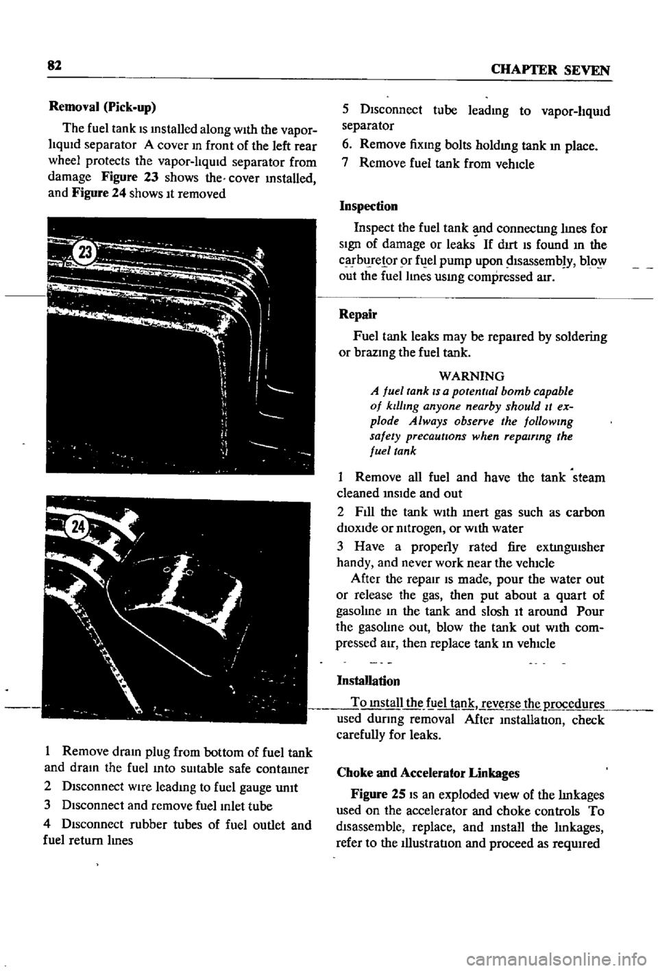
Figure
23
shows
the
cover
mstalled
and
Figure
24
shows
It
removed
I
Remove
dram
plug
from
bottom
of
fuel
tank
and
dram
the
fuel
mto
sUitable
safe
contamer
2
Disconnect
wire
leadmg
to
fuel
gauge
unIt
3
Disconnect
and
remove
fuel
Inlet
tube
4
Disconnect
rubber
tubes
of
fuel
outlet
and
fuel
return
lInes
5
Disconnect
tube
leadmg
to
vapor
liqUid
separator
6
Remove
fixmg
bolts
holdmg
tank
In
place
7
Remove
fuel
tank
from
vehIcle
Inspection
Inspect
the
fuel
tank
d
connectIng
lInes
for
SIgn
of
damage
or
leaks
If
dIrt
IS
found
In
the
carbl
relor
r
fuel
pump
upon
dlsassemb
y
blo
out
the
fuel
lines
usmg
compressed
air
Repair
Fuel
tank
leaks
may
be
repaired
by
soldering
or
brazmg
the
fuel
tank
WARNING
A
fuel
tank
IS
a
potential
bomb
capable
of
klllmg
anyone
nearby
should
It
ex
plode
Always
observe
the
followmg
safety
precautions
when
repairing
the
fuel
tank
1
Remove
all
fuel
and
have
the
tank
steam
cleaned
InSIde
and
out
2
F1l1
the
tank
WIth
Inert
gas
such
as
carbon
diOXide
or
mtrogen
or
WIth
water
3
Have
a
properly
rated
fire
extIngUisher
handy
and
never
work
near
the
vehicle
After
the
repair
IS
made
pour
the
water
out
or
release
the
gas
then
put
about
a
quart
of
gasolme
In
the
tank
and
slosh
It
around
Pour
the
gasolme
out
blow
the
tank
out
WIth
com
pressed
aIr
then
replace
tank
In
vehIcle
Installation
To
mstall
the
f
iel
tank
reverse
the
p
rocedur
used
dUring
removal
After
InstallatIon
check
carefully
for
leaks
Choke
and
Accelerator
Linkages
Figure
25
IS
an
exploded
VIew
of
the
lInkages
used
on
the
accelerator
and
choke
controls
To
disassemble
replace
and
mstall
the
lInkages
refer
to
the
IllustratIon
and
proceed
as
reqUIred