CHAPTER
NINE
ENGINE
ELECTRICAL
SYSTEM
The
electrIcal
system
has
undergone
slIght
yearly
changes
the
most
SignIficant
being
ill
the
distrIbutor
Some
models
have
a
smgle
contact
pomt
whIle
others
have
a
dual
pomt
system
De
talls
are
covered
m
the
dIstrIbutor
sectlon
The
electrIcal
system
IS
a
12
volt
negatIve
type
OPERATION
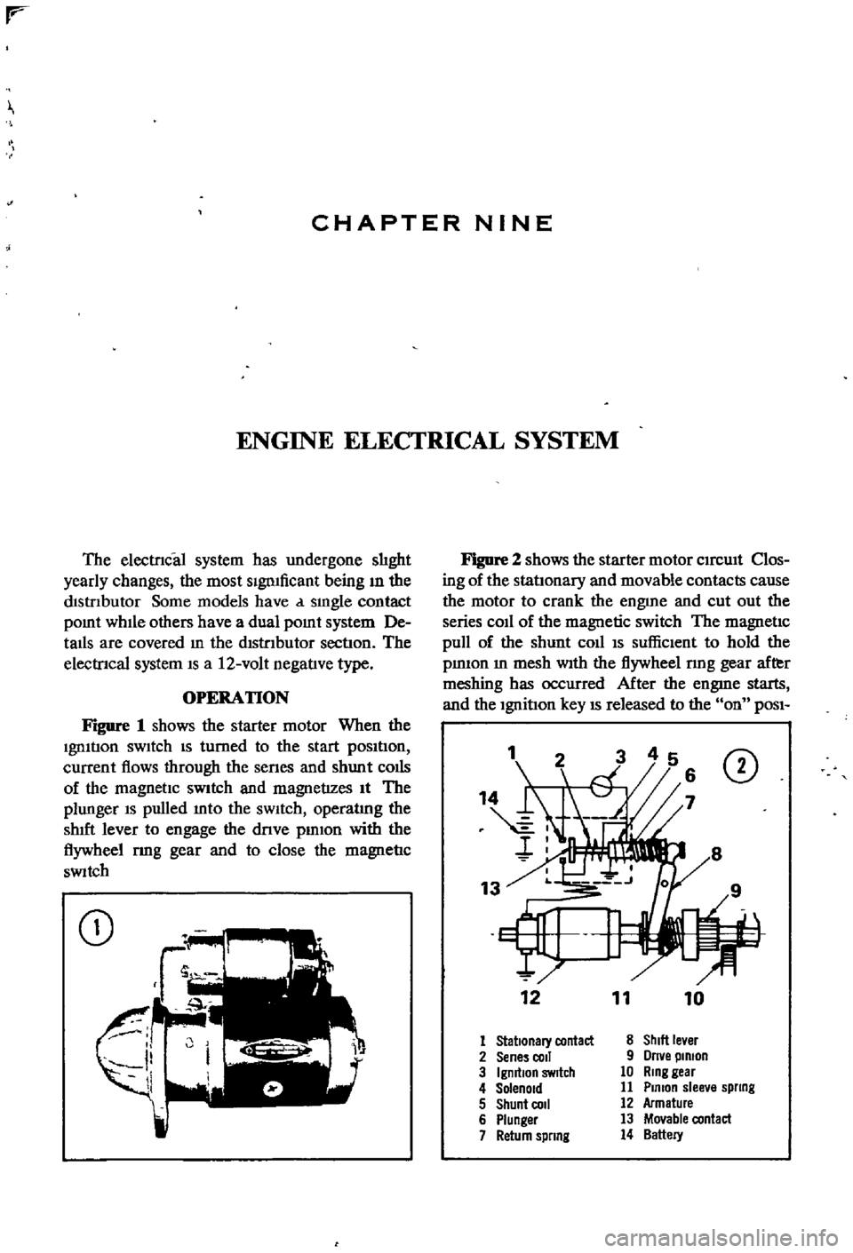
Figure
1
shows
the
starter
motor
When
the
Ignltlon
sWItch
IS
turned
to
the
start
pOSItIon
current
flows
through
the
senes
and
shunt
colis
of
the
magnetIc
SWitch
and
magnetizes
It
The
plunger
IS
pulled
mto
the
sWItch
operatlng
the
shIft
lever
to
engage
the
dnve
pmlon
with
the
flywheel
rmg
gear
and
to
close
the
magnetIc
SWitch
CD
Figure
2
shows
the
starter
motor
CIrcUIt
Clos
ing
of
the
statlonary
and
movable
contacts
cause
the
motor
to
crank
the
engme
and
cut
out
the
series
coIl
of
the
magnetic
switch
The
magnetic
pull
of
the
shunt
coll
IS
suffiCIent
to
hold
the
pmIOn
m
mesh
With
the
flywheel
nng
gear
after
meshing
has
occurred
After
the
engme
starts
and
the
Ignition
key
IS
released
to
the
on
POSI
1
CD
12
11
10
1
Stationary
contact
8
ShIlt
le
er
2
Sene
coli
9
Orne
pinion
3
IgmtlOn
SWitch
10
Ring
gear
4
Solenoid
11
Plmon
slee
e
spllng
5
Shunt
COil
12
Armature
6
Plunger
13
Movable
contact
7
Return
spllng
14
Battery
DIFFERENTIAL
REAR
AXLE
AND
REAR
SUSPENSION
155
i
I
I
I
REAR
SUSPENSION
ARM
SEDAN
Rear
Suspension
Arm
Removal
Sedan
1
Jack
up
the
rear
of
the
vehIcle
and
support
It
on
stands
2
Remove
wheel
and
brake
drum
3
DIsconnect
dnve
shaft
from
axle
shaft
4
Remove
handbrake
cable
from
lever
attached
to
wheel
cylInder
5
Plug
brake
tube
to
prevent
loss
of
brake
flwd
6
Remove
wheel
beanng
lock
nut
rear
axle
shaft
wheel
beanngs
and
OIl
seal
Remove
rear
brake
assembly
from
suspensIOn
arm
7
Place
Jack
under
suspenSIon
arm
remove
shock
absorber
from
lower
bracket
lower
Jack
gradually
remove
coll
spnng
spnng
seat
and
bumper
assembly
8
Remove
two
bolts
secunng
suspensIOn
arm
to
suspensIOn
member
and
remove
suspensIOn
arm
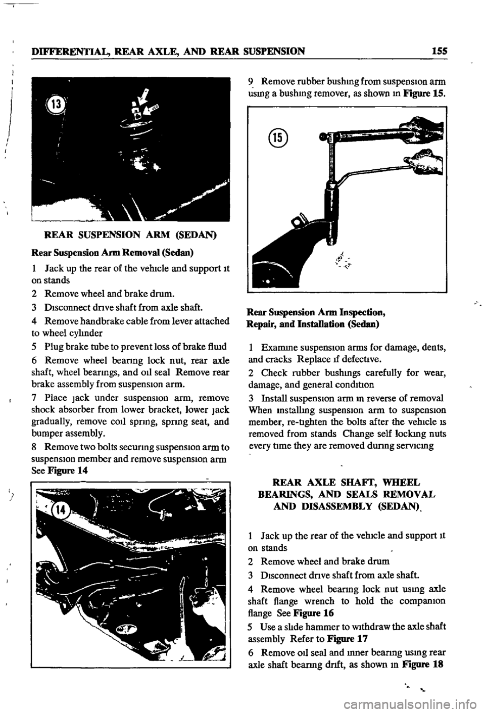
See
Figure
14
9
Remove
rubber
bushmg
from
suspensIon
arm
usmg
a
bushmg
remover
as
shown
In
Figure
15
@
Rear
SllSpension
Arm
Inspection
Repair
and
Installation
Sedan
1
Examme
suspensIOn
arms
for
damage
dents
and
cracks
Replace
tf
defectIve
2
Check
rubber
bushmgs
carefully
for
wear
damage
and
general
condItIon
3
Install
suspensIOn
arm
m
reverse
of
removal
When
Installmg
suspensIOn
arm
to
suspensIOn
member
re
tIghten
the
bolts
after
the
vehIcle
IS
removed
from
stands
Change
self
lockmg
nuts
every
tIme
they
are
removed
dunng
semcmg
REAR
AXLE
SHAFf
WHEEL
BEARINGS
AND
SEALS
REMOVAL
AND
DISASSEMBLY
SEDAN
1
Jack
up
the
rear
of
the
vehIcle
and
support
It
on
stands
2
Remove
wheel
and
brake
drum
3
DIsconnect
dnve
shaft
from
axle
shaft
4
Remove
wheel
bearmg
lock
nut
usmg
axle
shaft
flange
wrench
to
hold
the
companIOn
flange
See
Figure
16
5
Use
a
slIde
hammer
to
Withdraw
the
axle
shaft
assembly
Refer
to
Figure
17
6
Remove
011
seal
and
Inner
bearmg
usmg
rear
axle
shaft
bearmg
dnft
as
shown
In
Figure
18