1968 DATSUN 510 transmission
[x] Cancel search: transmissionPage 3 of 252
CON1EN1S
CHAPTER
ONE
GENERAL
INFORMATION
Introduction
Model
Identification
CHAPTER
TWO
PERIODIC
MAINTENANCE
RoutIne
checks
Pen
odic
checks
CHAPTER
THREE
TROUBLESHOOTING
EqUIpment
Starter
ChargIng
system
EngIne
Igmtlon
system
Fuel
system
Exhaust
emIssIon
control
CHAPTER
FOUR
ENGINE
AND
IGNITION
TUNE
UP
EqUIpment
Battery
Spark
plugs
DIstrIbutor
Igmtlon
timIng
CHAPTER
FIVE
ENGINE
LUBRICATION
SYSTEM
Descnptlon
Lubncation
cIrcuIt
SpecIficatiOns
and
dImensIons
EngIne
lubncation
and
maIntenance
Recommended
lubncants
Clutch
TransmIssiOn
Brakes
Steenng
and
suspension
TIre
wear
analysIs
Wheel
balancIng
Idle
speed
and
Idle
mIXture
Dwell
angle
setting
CompressIon
test
Valve
clearance
adjustment
AddlllOnal
checks
Oil
pump
I
6
t
1
4
V
9
t
1
20
27
Page 4 of 252
II
CHAPTER
SIX
ENGINE
Cylmder
block
Crankshaft
PistOns
and
connectmg
rods
Cyhnder
head
Camshaft
Valve
mechamsm
Camshaft
dnve
Mamfolds
011
pump
Fuel
pump
Carburetor
Emission
control
devIces
Engme
removal
Engme
dISassembly
Pistons
and
connectmg
rods
Cyhnder
head
Engme
mspectIon
and
replllr
Engme
reassembly
Service
data
and
speCifications
CHAPTER
SEVEN
FUEL
SYSTEM
Air
cleaner
Fuel
strlllner
Fuel
pump
Carburetor
Fuel
tank
1
CHAPTER
EIGHT
COOLING
SYSTEM
DescnptIon
Water
pump
Fan
clutch
Thermostat
Radiator
CHAPTER
NINE
ENGINE
ELECTRICAL
SYSTEM
Starter
Overrunmng
clutch
assembly
ChargIng
ClrcUlt
Alternator
Alternator
output
Voltage
regulator
DIstrIbutor
Condenser
Igrntlon
cod
SpeCifications
Spark
plugs
CHAPTER
TEN
EMISSION
CONTROL
SYSTEM
Exhaust
emiSSIOn
control
Crankcase
emission
control
Air
mJectlon
system
Engme
modifications
Evaporative
emiSSion
control
Exhaust
system
CHAPTER
ELEVEN
CLUTCH
TRANSMISSION
AND
DRIVESHAFT
Clutch
TransmissIon
Master
cyhnder
TransmissIon
data
and
speCIfications
Operating
cyhnder
Dnveshaft
Withdrawal
lever
adjustment
Dnveshaft
data
and
speCIfications
Clutch
system
bleedmg
Automatic
transmIssIon
checks
Clutch
data
and
speCIfications
31
62
84
91
114
127
Page 6 of 252
CHAPTER
ONE
GENERAL
INFORMATION
This
manual
provides
maintenance
informa
tIon
on
the
Datsun
510
Series
and
521
Series
of
vehlcles
The
510
Series
includes
the
two
door
sedan
four
door
sedan
and
station
wagon
The
521
Senes
IS
the
pIck
up
truck
Coverage
is
from
1968
through
1972
models
All
models
use
the
L16
engme
a
96
horse
power
four
cylmder
overhead
camshaft
design
The
510
has
a
fully
synchronized
four
speed
manual
or
three
speed
automatic
transmisSIon
The
521
has
a
four
speed
manual
transmission
only
In
1972
horsepower
ratIng
was
lowered
to
92
horsepower
due
to
changes
m
emission
control
device
requirements
Figure
1
is
an
over
all
view
of
the
four
door
sedan
Figure
2
shows
the
station
wagon
and
Figure
3
illustrates
the
pick
up
truck
Over
the
years
the
510
and
521
series
have
remained
essentIally
the
same
with
the
excep
tion
of
changes
to
the
emISsion
control
systems
and
overall
body
stylmg
In
this
manual
every
effort
has
been
made
to
pinpoint
significant
c
if
ferences
between
model
years
The
use
of
SpecIal
tools
and
test
equipment
has
been
avoided
wherever
possible
When
necessary
special
tools
and
test
equipment
are
illustrated
either
in
actual
use
or
alone
A
well
equipped
mecharuc
may
find
he
can
substitute
similar
tools
or
make
his
own
to
fulfill
a
e
Ii
ment
Recommendations
are
occasionally
made
to
refer
servIce
or
mamtenance
to
a
Datsun
dealer
or
a
SpecIaliSt
in
a
specIfied
field
In
these
cases
work
WIll
probably
be
done
more
qUlckly
and
economIcally
than
if
the
mecharuc
performs
them
himself
MODEL
IDENTIFICATION
Body
Number
Plate
The
body
number
IS
stamped
on
the
fire
wall
in
the
engine
compartment
The
numbers
give
the
chasSIS
model
and
serial
number
Model
Identification
Plate
The
model
Identification
plate
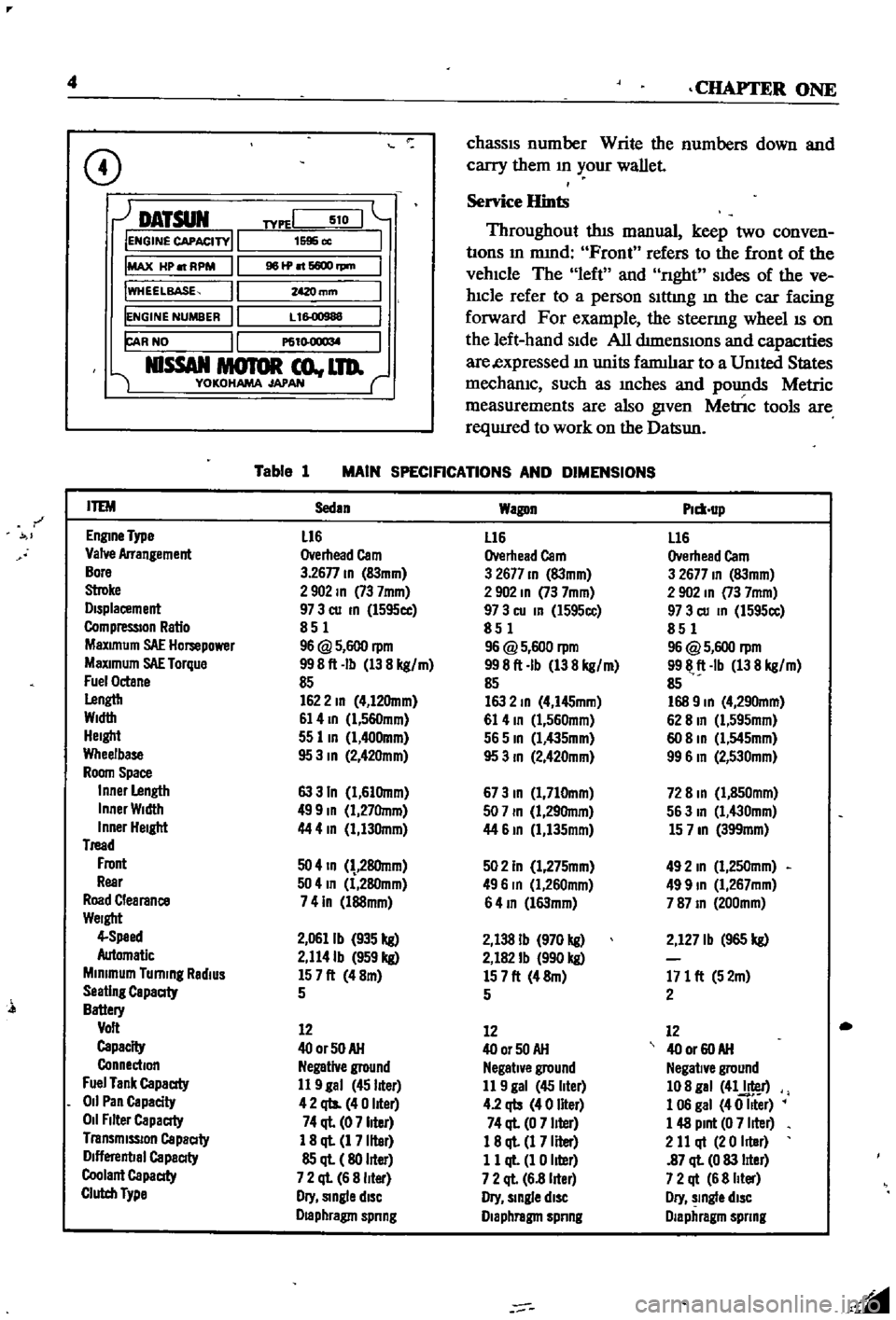
Figure
4
is
mounted
WIthin
the
engine
compartment
TIns
plate
gIves
engine
number
and
veh1cle
number
Engine
Identification
The
engine
identrlicatlon
marking
is
stamped
on
the
right
hand
SIde
of
the
cylinder
block
just
below
the
third
and
fourth
sp8l
k
plugs
Model
Identification
Numbel
ll
The
following
numbers
have
been
assigned
to
the
510
and
52
I
Series
vehicles
oj
Page 9 of 252
4
CHAPTER
ONE
chassIs
number
Write
the
numbers
down
and
carry
them
ill
your
wallet
Service
Hints
Throughout
thIs
manual
keep
two
conven
bons
ill
mmd
Front
refers
to
the
front
of
the
vehicle
The
left
and
nght
sides
of
the
ve
hicle
refer
to
a
person
sittIng
ill
the
car
facing
forward
For
example
the
steenng
wheelIS
on
the
left
hand
Side
All
dimensIOns
and
capacities
are
expressed
ill
units
fanuhar
to
a
Umted
States
mechaniC
such
as
illches
and
pounds
Metric
measurements
are
also
given
Metnc
tools
are
reqUITed
to
work
on
the
Datsun
CD
DATSUN
IENGINE
CAPACITY
IMAX
HP
RPM
IWHEELBASE
IENGINE
NUMBER
FAR
NO
NlSSAN
MOTOR
co
LTD
YOKOHAMA
JAPAN
TYPEI
510
1595
cc
961P
6600
rpm
mm
L
1
00988
P61
l
O
1
l
M
Table
1
MAIN
SPECIFICATIONS
AND
DIMENSIONS
r
ITEM
Sedan
Wagon
Plm
up
EnglDe
Type
L16
L16
L16
Valve
Arrangement
Overhead
Cam
Overhead
Cam
Overhead
Cam
Bore
3
26n
ID
83mm
3
2677
ID
83mm
3
2677
ID
83mm
Stroke
2902
ID
73
7mm
2
902
ID
73
7mm
2
902
In
73
7mm
Displacement
97
3
cu
ID
l595cc
97
3
cu
In
l595cc
97
3
cu
ID
1595cc
CompressIOn
Ratio
851
851
851
MaXimum
SAE
Hompower
96
@
5
600
rpm
96
@
5
600
rpm
96
@
5
600
rpm
MaXimum
SAE
Torque
998ft
Ib
138
kg
m
998ft
Ib
138
kg
m
9911
ft
Ib
138
kg
m
Fuel
Octane
85
85
85
Lengtb
1622
ID
4
12Omm
163
2
ID
4
I45mm
168
9
ID
4
290mm
Width
61
4
ID
l
560mm
61
4
ID
1
560mm
62
8
In
Cl
595mm
Height
55
lID
1
400mm
565
ID
Cl
435mm
60
8
ID
Cl
545mm
Wheelbase
95
3
ID
2
42Omm
95
3
ID
2
420mm
99
6
In
2
530mm
Room
Space
Inner
Length
63
3
In
1
61Omm
673
ID
1
710mm
72
8
ID
1
850mm
Inner
Width
499
ID
1
27Omm
507
ID
1
29Omm
563
In
1
430mm
Inner
Height
44
4
In
1
130mm
44
61D
1
135mm
15
7
ID
399mm
Tread
Front
50
4
ID
28Omm
502
In
1
275mm
492
In
1
250mm
Rear
504
In
1
280mm
496
In
Cl
260mm
499
ID
1
267mm
Road
Clearance
741n
l88mm
64
ID
l63mm
787
ID
200mm
Weight
4
Speed
2
0611b
935
kg
2
138
Ib
970
kg
2
127
Ib
965
kg
Automatic
2
114Ib
959
kg
2
182
Ib
990
kg
Minimum
Turning
RadiUS
157ft
48m
157ft
48m
171
ft
52m
Seating
Capaaty
5
5
2
Battery
Volt
12
12
12
Capacity
400rSOAH
400r50AH
40
or
60
AH
Connection
Negative
ground
Negative
ground
Negative
ground
Fuel
Tank
Capaaty
11
9
gal
45
liter
11
9
gal
45
liter
108
gal
41J
r
011
Pan
Capacity
42
qts
40
liter
4
2
qb
40
liter
1
06
gal
40
Iller
011
Filter
Capaaty
74
ql
07
liter
74
ql
0
7
liter
1
48
Pint
0
7
liter
Transmission
Capaaty
1
8
ql
1
7
liter
18
ql
1
7
Iller
2
11
qt
20
Iller
Dlflerenbal
Capaaty
85
ql
80
liter
11
ql
1
0
liter
87
ql
0
83
lIter
Coolant
Capaaty
7
2
ql
6
8
liter
7
2
ql
6
8
lIter
7
2
qt
6
8
Iller
Clutch
Type
Dry
Single
diSC
Dry
slDgle
diSC
Dry
slDgle
diSC
Draphragm
spnng
Diaphragm
spnng
Diaphragm
spnng
l
Page 10 of 252
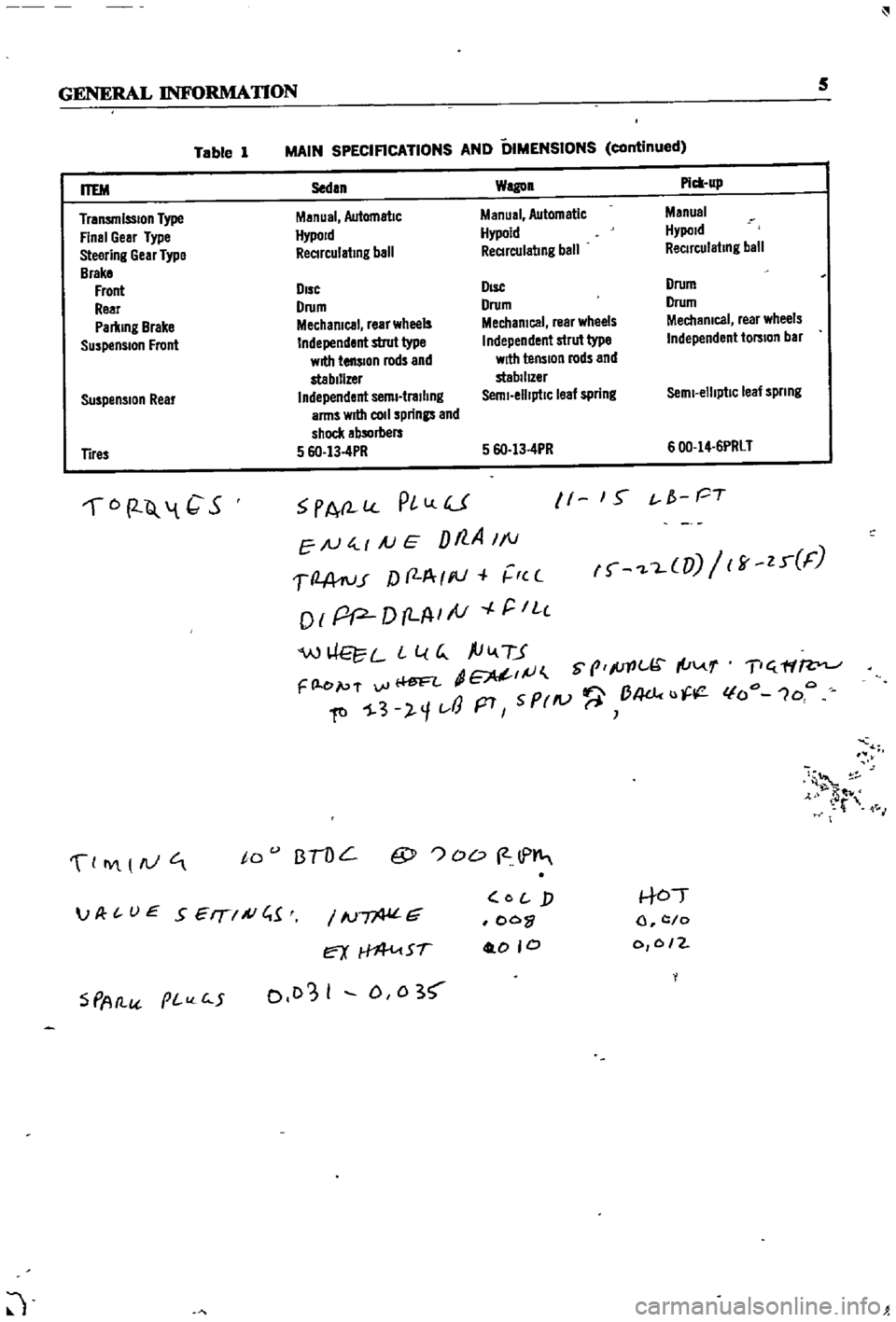
GENERAL
INFORMATION
5
Table
1
MAIN
SPECIFICATIONS
AND
DIMENSIONS
continued
Suspension
Rear
Sedan
Wagon
Pick
up
Manual
Automatic
Manual
Automatic
Manual
HypoJd
Hypoid
Hypold
ReCIrculating
ball
ReCIrculating
ball
ReCirculating
ball
DIsc
DIsc
Drum
Drum
Drum
Drum
Mechanical
rear
wheels
Mechanical
rear
wheels
Mechanical
rear
wheels
Independent
strut
type
Independent
strut
type
Independent
torsion
bar
with
tension
rods
and
with
tension
rods
and
stabilizer
stabilIZer
Independent
semi
trailing
Semi
elliptiC
leaf
spring
Semi
elliptic
leaf
spnng
arms
wrtII
coli
springs
and
shock
absorbers
5
6O
13
4PR
5
6O
13
4PR
600
14
6PRLT
ITEM
Transmission
Type
Final
Gear
Type
Steering
Gear
Type
Brake
Front
Rear
Parking
Brake
Suspension
Front
Tires
6
2
Q
1
C
S
PA
l
PlLlU
EN
4
1
AJ
E
Dt7
A
1
1
1
2
A
ru
r
f
f
A
I
III
r
c
o
I
pP
D
LA
I
tV
r
IL
c
W
L
L
l
G
ftiv
TJ
dE
IJ
S
prlc
I
u
F
l
e
p
f
vi
Ii
ftl
1
3
l
1t
J
p7
5
PrlV
B4dc
u
11
1
S
t
f
PT
f
L
UJ
ff
zr
F
T
ff
lfo
1oo
4
t
M
0
IY
AJ
to
BTOL
@
OD
2
lP
S
PAtl
pI
c
5
IN
G
ex
Sf
0103
I
D
0
3
O
j
oo
0
0
0
to
l
c
o
0
0
2
JP
t
UE
SEIT
A
C
1
J
Page 17 of 252

12
CHAPTER
THREE
13
IMPROPER
IDLE
MIXTURE
Roats
slowly
between
13
17
14
SMALl
SPARK
GAP
or
DEFECTIVE
POINTS
Slight
float
between
14
16
ignItIOn
switch
If
the
starter
still
fails
to
crank
properly
remove
the
starter
and
test
it
2
Starter
turns
but
does
not
engage
with
engine
This
trouble
is
usually
a
defective
pInion
or
sole
noid
shlfting
fork
It
may
also
be
that
the
teeth
on
the
pInion
flywheel
ring
gear
or
both
are
worn
down
too
far
to
engage
properly
3
Starter
engages
but
will
not
dISengage
when
IgmtlOn
switch
IS
released
TIns
trouble
is
usually
caused
by
a
sticking
sole
nOid
but
occasionally
the
pmlOn
can
jam
on
the
flywheel
With
manual
transmissions
the
pinion
can
be
temporanly
freed
by
rockmg
the
car
in
high
gear
Naturally
this
IS
not
poSSible
in
auto
matics
the
starter
must
be
removed
4
Loud
grinding
noISes
when
starter
runs
TIns
usually
means
the
teeth
on
the
pinion
and
or
flywheel
are
not
meshing
properly
It
may
also
mean
the
over
running
clutch
IS
broken
In
the
first
case
remove
the
starter
and
examine
the
gear
teeth
In
the
latter
remove
the
starter
and
replace
the
pmion
dnve
assembly
CHARGING
SYSTEM
Charging
system
troubles
may
be
in
the
alter
nator
voltage
regulator
or
fan
belt
The
follow
ing
symptoms
are
typical
1
Alternator
warning
lamp
does
not
come
on
when
IgmtlOn
is
turned
on
This
may
indicate
a
defective
ignition
switch
battery
voltage
regulator
or
lamp
Frrst
try
to
15
HEAD
GASKET
LEAK
Roats
between
5
19
16
RESTRICTm
EXHAUST
SYSTEM
Normal
when
first
started
Drops
to
0
as
rpm
Increases
May
eventually
rrse
to
about
16
start
the
car
If
it
doesn
t
start
check
the
igllltlon
sWitch
and
battery
If
the
car
starts
find
the
voltage
regulator
and
disconnect
the
wlute
red
Wire
this
is
the
lamp
wire
Ground
the
wire
If
the
lamp
hghts
the
voltage
regulator
is
defective
not
properly
grounded
try
tightening
the
mounting
screws
or
the
alternator
brushes
are
not
contactmg
the
commutator
If
the
lamp
does
not
light
when
the
wire
IS
grounded
the
lamp
is
probably
burned
out
replace
It
2
Alternator
warning
lamp
comes
on
and
stays
on
This
usually
mdicates
that
no
chargmg
is
takmg
place
Frrst
check
the
fan
belt
tension
and
adlust
if
necessary
Check
the
battery
condition
with
the
hydrometer
and
check
all
electrical
connec
tions
m
the
chargmg
system
Fmally
isolate
the
trouble
to
the
alternator
or
voltage
regulator
3
Alternator
warmng
lamp
flashes
erratically
This
usually
indicates
the
chargmg
system
is
workmg
intermittently
Check
the
fan
belt
ten
sion
and
all
electncal
connections
m
the
charg
ing
system
Check
alternator
brushes
and
cODlh
tlon
of
the
commutator
4
Baltery
reqUires
frequent
additiOns
of
water
or
lamps
require
frequent
replacement
The
alternator
IS
probably
overchargmg
the
bat
tery
The
voltage
regulator
is
probably
faulty
check
it
using
the
procedures
given
in
Chaper
Nme
5
ExceSSive
noISe
from
he
alternator
Check
for
loose
alternator
mountmg
The
Page 21 of 252
16
CHAPTER
TIlREE
sary
Also
check
all
parts
for
mlSaltgnment
and
uneven
wear
TRANSMISSION
1
Difficult
to
mesh
gears
Make
certam
the
clutch
pressure
plate
and
re
lease
beanng
are
m
good
condItion
The
trouble
can
be
caused
by
worn
gears
shaft
and
or
bear
mgs
DISassemble
and
repaIr
as
requIred
Also
can
be
caused
by
msufficlent
operatmg
stroke
due
to
worn
or
loose
sltdmg
parts
or
a
defective
synchronIZer
DIsassemble
carefully
InSpect
and
replace
as
requIred
2
Gears
slip
out
of
mesh
Generally
thIS
trouble
occurs
when
the
mterlock
plunger
check
ball
and
or
spnng
IS
weakened
or
worn
The
trouble
can
also
be
caused
by
worn
fork
rod
ball
groove
damaged
bearings
or
dam
aged
gears
DIsassemble
carefully
mspect
and
replace
as
required
3
NOIse
If
nOISes
are
heard
wIth
the
engme
idlmg
and
the
clutch
disengaged
the
nOIse
IS
probably
conung
from
the
transmISSIOn
Several
Items
can
cause
nOISes
either
smgly
or
m
combmatIon
Check
the
qualIty
and
quantity
of
lubrIcant
in
the
trans
mISSIon
Replace
or
replenISh
as
necessary
Worn
bearIngs
wIll
usually
produce
a
lugh
humming
at
hIgh
speed
and
a
cycltc
knockIng
sound
at
low
speed
Worn
or
damaged
splInes
and
bushmgs
will
also
cause
nOIse
BRAKES
1
Brake
pedal
goes
to
floor
There
are
numerous
causes
for
thIS
includIng
excessIvely
worn
Itnmgs
aIr
in
the
hydraultc
sys
tem
leaky
brake
lmes
leaky
wheel
cylmders
or
leaky
or
worn
master
cylmder
Check
for
leaks
and
thIn
brake
linmgs
Bleed
and
adjust
the
brakes
If
thIS
doesn
t
cure
the
trouble
rebwld
wheel
cylmders
a
nd
or
master
cylmder
2
Spongy
pedal
Normally
caused
by
aIr
m
the
system
blee
d
and
adjust
the
brakes
3
Brakes
pull
Check
brake
adjustment
Also
check
for
contam
inated
brake
Itmngs
from
leaks
leaky
wheel
cyltnders
loose
caltpers
frozen
or
seIZed
pIstons
and
restrIcted
brake
lmes
or
hoses
In
addItion
check
front
end
alignment
and
suspensIOn
dam
age
such
as
broken
front
or
rear
sprmgs
shocks
etc
Check
condItIon
of
tIres
4
Brakes
squeal
or
chatter
Check
brake
lmmg
thickness
and
brake
drum
roundness
Ensure
that
the
shoes
have
cham
ferred
ends
and
are
not
loose
Inspect
the
condI
tion
of
the
rotors
on
the
front
wheel
dISC
brakes
to
make
certain
they
are
not
scored
or
damaged
Clean
away
all
dIrt
on
shoes
pads
rotors
or
drums
5
Draggmg
brakes
Check
brake
adjustment
includmg
handbrake
Check
for
broken
or
weak
shoe
return
springs
swollen
rubber
parts
due
to
unproper
brake
flUId
or
other
contammatIon
Clean
or
replace
de
fectIve
parts
6
Hard
pedal
Check
brake
linmgs
for
contammation
Also
check
for
restrIcted
brake
lines
and
hoses
7
High
speed
fade
Check
for
dIstorted
or
out
of
round
drums
and
contamInated
brake
lmmgs
Make
certam
the
recommended
brake
flUId
IS
used
Dram
entIre
system
and
refill
If
In
doubt
8
Pulsatmg
pedal
Check
for
dIStorted
or
out
of
round
drums
or
rotors
Check
for
excessIVe
brake
dISC
run
out
STEERING
AND
SUSPENSION
NOTE
Unusual
steermg
pullmg
or
wandermg
IS
usually
caused
by
bent
or
otherwise
mIsaligned
suspenszon
parts
Because
of
the
speCialized
equIp
ment
reqUired
to
evaluate
and
correct
these
faults
It
IS
recommended
t
tat
servIce
to
the
steermg
and
suspension
system
be
referred
to
your
Datsun
dealer
oca
quallfied
specrallst
m
thiS
field
1
VibratIOn
felt
m
steermg
wheel
VIbratIon
can
be
caused
by
several
thmgs
includ
ing
lll1proper
aIr
pressure
m
tIres
uneven
wear
Page 29 of 252

P
r
OVll
t
ate
I
l
h
l
JlA
ye
I
o
ctg
fI
O
0
I
d
1e
d
c
Ji
uo
JJ
cb
c
s
rlr
I
l
4
c
1
2
24
CHAPTER
FOUR
block
and
should
be
used
as
the
reference
point
m
II
1akmg
adjustments
6
With
a
piece
of
white
chalk
mark
a
hne
down
the
center
of
the
pomter
and
mark
the
timing
groove
on
the
crankshaft
pulley
which
IS
to
be
used
m
tImmg
the
engine
SpecIficatIon
for
tun
ing
reqUIres
trlhmg
at
10
degrees
before
top
dead
center
wluch
would
be
the
fourth
mark
from
the
left
end
of
the
row
of
marks
7
Loosen
the
hold
down
bolt
at
the
base
of
the
dlstnbutor
8
Locate
the
slow
speed
1
Ile
adjustIng
screw
on
the
carburetor
so
that
Ile
speed
can
be
adjusted
whIle
runnmg
Also
locate
throttle
adJustmg
screw
9
Start
engme
and
adjust
speed
With
the
adJust
ing
screws
to
the
readmgs
below
Smgle
pomt
dIStributor
600
rpm
Dual
pomt
trlbutor
700
rpm
10
Alternate
adjustment
of
the
two
screws
untIl
the
smoothest
Idle
at
the
proper
speed
IS
achieved
11
Pomt
the
tlIrung
lIght
at
the
stationary
pomter
When
the
lIght
flashes
the
timmg
mark
n
the
crankshaft
pulley
should
hne
up
With
the
mark
on
the
stationary
pomter
If
It
does
not
exactly
Ime
up
rotate
the
dlstnbutor
gradually
untIl
the
marks
align
mdlcatlng
correct
timmg
12
Shut
off
the
engme
remove
the
tmung
lIght
and
tachometer
tighten
the
hold
down
bolt
on
the
dlStnbutor
and
connect
the
vacuum
advance
hne
to
the
tli
tnbutor
IGNITION
TIMING
IDLE
SPEED
IDLE
MIXTURE
DUAL
POINT
DISTRIBUTOR
ONLY
The
followmg
applies
to
velucles
With
dual
pomt
distributor
and
an
exhaust
emission
con
trol
deVice
If
these
procedures
are
followed
ha
ul
exhaust
emisSion
should
be
below
the
maximum
allowable
level
1
Locate
the
Idle
and
throttle
adJustmg
screws
on
the
carburetor
2
Warm
up
the
engine
thoroughly
3
Connect
tachometer
and
tmung
light
4
Set
the
Id
le
speed
at
700
rpm
With
the
Idle
adjust
screw
5
Adjust
IgnltJ
on
tuning
at
10
degrees
before
top
dead
center
6
Increase
the
speed
of
the
engme
to
2
000
rpm
With
the
accelerator
or
throttle
hnkage
and
hold
for
about
15
seconds
7
Return
to
Idle
for
one
mmute
8
Set
the
engme
to
best
Idle
at
750
rpm
770
rpm
for
automatJ
c
transIDlsslOn
With
the
Idle
and
throttle
adJustmg
screws
9
Re
uce
engme
speed
at
700
rpm
720
rpm
for
automatic
transmission
by
turnmg
the
Idle
adJustmg
screw
clockWise
for
a
leaner
IlliXture
10
Connect
a
wife
lead
between
the
advance
ami
retard
Side
tenrunals
See
Figure
4
Speed
should
drop
from
100
to
150
rpm
11
Check
IgIl1tIon
tmung
With
tImmg
light
It
should
now
be
at
top
d
ad
center
12
If
the
tlmmg
IS
nSJt
correct
stop
the
engme
and
adjust
the
retarded
breaker
pomt
13
Start
the
engme
and
reclieck
ili
tmung
If
l
incorrect
reset
the
retarded
breaker
pomt
until
it
IS
correct
Repeat
s
nece
s
14
Disconnect
the
wife
bet
reen
the
advance
and
retard
termmals
15
Recheck
tmung
It
should
be
10
degrees
before
top
dead
center
16
If
mcorrect
repeat
the
above
procedures
un
tIl
satIsfactory
17
T
he
Idle
speed
of
automatic
transnllsslOn
vehicles
should
be
about
575
rpm
With
the
gear
j
selector
m
the
dhve
poSltlon
c
t
DWELL
ANGLE
SETIING
1
Connect
the
dwell
angle
meter
2
PLoJust
dwell
angle
to
49
to
55
degrees
OMPRESSION
TEST
I
A
compressIOn
test
IS
performed
to
check
for
worn
piston
nngs
or
to
detect
the
cause
of
a
low
speed
miss
Before
undertaking
the
test
el
llmate
the
pOSSibility
of
sticky
valves
by
usmg
one
of
the
oil
additives
deSigned
for
the
purpose
With
valves
free
test
compressIOn
as
follows
1
Run
the
engme
for
15
to
20
mmutes
untIl
normal
operating
temperatures
are
obtained
2
Shut
off
engme
remove
arr
cleaner
and