1968 DATSUN 510 transmission
[x] Cancel search: transmissionPage 74 of 252
FUEL
SYSTEM
69
CARBURETOR
The
carburetor
IS
an
Hltach1
Type
DAF328
Several
varIations
are
used
dependmg
on
the
model
year
type
of
transmissIOn
and
the
emIS
SIon
control
system
The
dIfferent
models
are
the
same
as
far
as
basiC
operation
IS
concerned
Therefore
the
followmg
dISCUSSIon
covers
a
typIcal
carburetor
The
automatIc
choke
IS
used
on
automatIc
transmISSIon
and
1972
models
only
All
other
chokes
are
manual
Refer
to
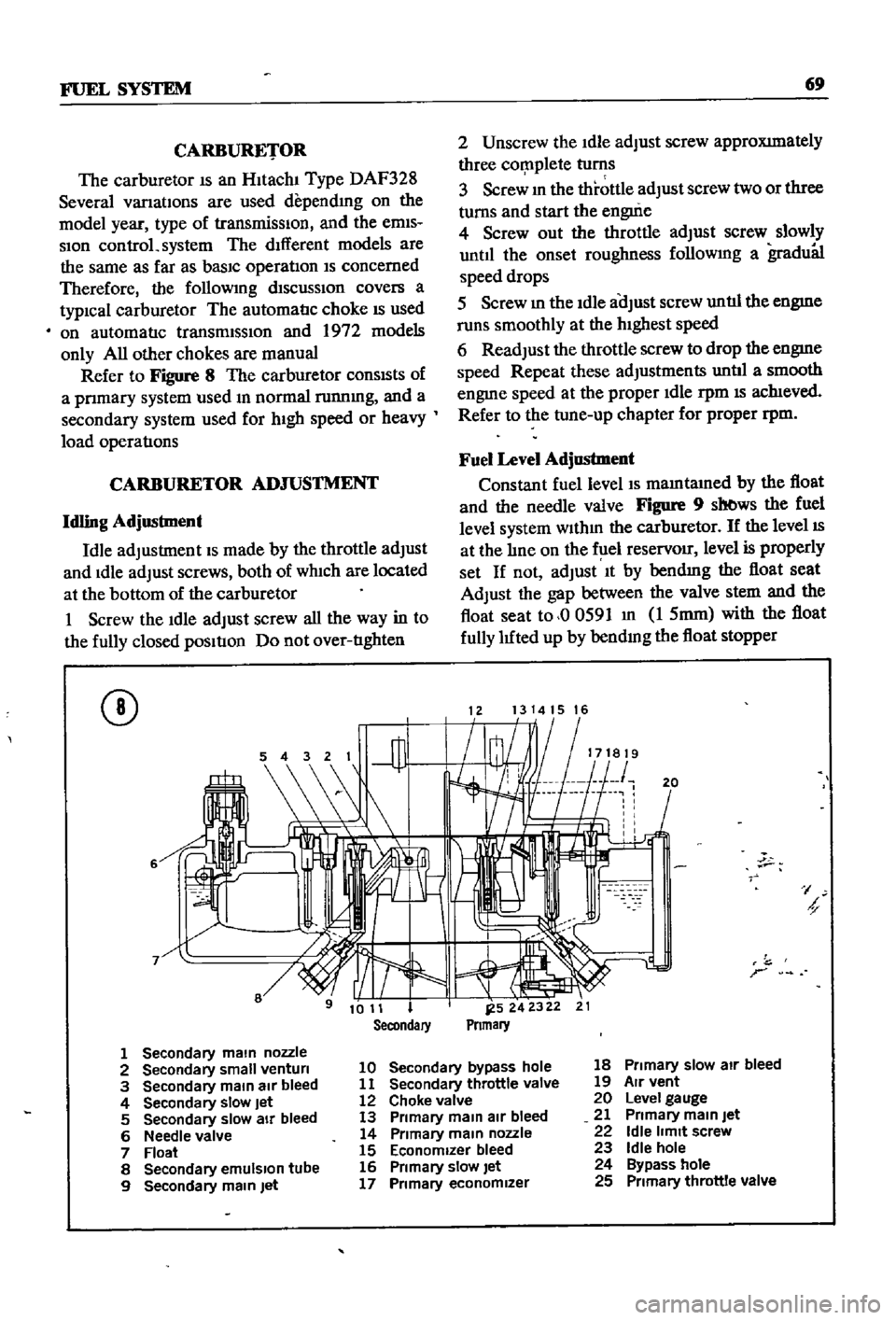
Figure
8
The
carburetor
conSIsts
of
a
pnmary
system
used
m
normal
runnmg
and
a
secondary
system
used
for
hIgh
speed
or
heavy
load
operatIons
CARBURETOR
ADJUSTMENT
Idling
Adjustment
Idle
adjustment
IS
made
by
the
throttle
adjust
and
Idle
adjust
screws
both
of
wh1ch
are
located
at
the
bottom
of
the
carburetor
1
Screw
the
Idle
adjust
screw
all
the
way
in
to
the
fully
closed
pOSItIon
Do
not
over
tIghten
CD
6
2
Unscrew
the
Idle
adjust
screw
approXImately
three
cor
nplete
turns
3
Screw
m
the
throttle
adjust
screw
two
or
three
turns
and
start
the
engui
e
4
Screw
out
the
throttle
adjust
screw
slowly
until
the
onset
roughness
followmg
a
gradu81
speed
drops
5
Screw
m
the
Idle
aOJust
screw
untIl
the
engme
runs
smoothly
at
the
hIghest
speed
6
Readjust
the
throttle
screw
to
drop
the
engme
speed
Repeat
these
adjustments
untIl
a
smooth
engme
speed
at
the
proper
Idle
rpm
IS
ach1eved
Refer
to
the
tune
up
chapter
for
proper
rpm
Fuel
Level
Adjustment
Constant
fuel
level
IS
mamtamed
by
the
float
and
the
needle
valve
Figure
9
sb
ws
the
fuel
level
system
wlthm
the
carburetor
If
the
level
IS
at
the
lIne
on
the
f
lel
reservOir
level
is
properly
set
If
not
adjust
It
by
bendmg
the
float
seat
Adjust
the
gap
between
the
valve
stem
and
the
float
seat
to
00591
m
1
5mm
with
the
float
fully
luted
up
by
bendmg
the
float
stopper
1213141516
20
I
h
r
1
Secondary
main
nozzle
2
Secondary
small
venturi
10
Secondary
bypass
hole
18
Primary
slow
air
bleed
3
Secondary
main
air
bleed
11
Secondary
throttle
valve
19
Air
vent
4
Secondary
slow
Jet
12
Choke
valve
20
Level
gauge
5
Secondary
slow
air
bleed
13
Primary
main
air
bleed
21
Primary
main
Jet
6
Needle
valve
14
Primary
main
nozzle
22
Idle
limit
screw
7
Float
15
Economizer
bleed
23
Idle
hole
8
Secondary
emulSion
tube
16
Primary
slow
let
24
Bypass
hole
9
Secondary
main
Jet
17
Primary
economizer
25
Primary
throttle
valve
Page 95 of 252
90
CHAPTER
EIGHT
degrees
C
The
maXImum
WIdth
of
the
thermo
stat
openIng
should
be
0315
In
8mm
3
If
the
thermostat
IS
defectIve
or
If
you
have
an
doubts
about
It
mstall
a
new
one
4
When
Installmg
the
thermostat
m
the
hous
Ing
be
certaIn
to
place
the
spnng
end
down
Coat
both
SIdes
of
the
gasket
WIth
sealer
to
pre
vent
leaks
and
tIghten
the
mountlng
nuts
securely
RADIATOR
The
radIator
IS
of
conventional
desIgn
A
draIn
cock
IS
proVIded
at
the
bottom
back
to
perrmt
drainIng
The
system
IS
pressurized
and
the
rehef
valve
incorporated
In
the
filler
cap
mamtains
the
pressure
at
approximately
12
8
Ib
in
0
9
kg
cm
Coolant
capacity
is
1
691
gallons
6
4
lIters
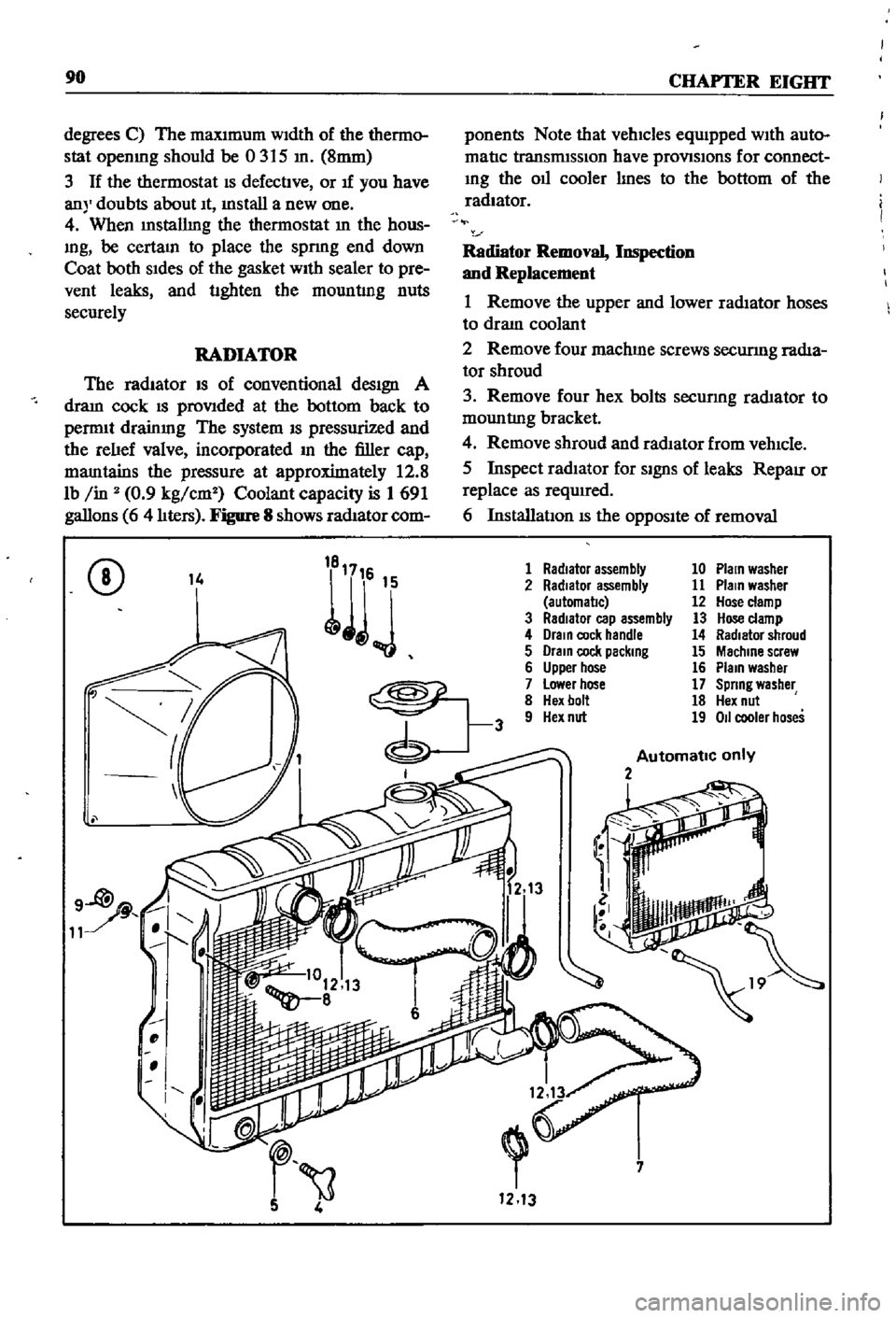
Figure
8
shows
radIator
com
ponents
Note
that
vehicles
equIpped
WIth
auto
matIc
transmISSIon
have
provlSlons
for
connect
Ing
the
011
cooler
lInes
to
the
bottom
of
the
radiator
Radiator
Removal
Inspection
and
Replacement
1
Remove
the
upper
and
lower
radIator
hoses
to
draIn
coolant
2
Remove
four
machme
screws
securmg
radIa
tor
shroud
3
Remove
four
hex
bolts
secunng
rad1ator
to
mountlng
bracket
4
Remove
shroud
and
radIator
from
vehIcle
5
Inspect
radIator
for
SignS
of
leaks
RepaIr
or
replace
as
required
6
InstallatIon
IS
the
OppOSIte
of
removal
CD
14
1
Radiator
assembly
10
Plain
washer
2
Radiator
assembly
11
Plain
washer
automal1c
12
Hose
clamp
3
RadIator
cap
assembly
13
Hose
clamp
4
Drain
cock
handle
14
Radiator
shroud
5
Drain
cock
packing
15
Machine
screw
6
Upper
hose
16
Plain
washer
7
Lower
hose
17
Spring
washer
8
Hex
bolt
18
Hex
nut
9
Hex
nut
19
011
cooler
hoses
Automatic
only
2
i
7
1213
Page 124 of 252
EMISSION
CONTROL
S
IS
TEM
SEDAN
AND
SlATION
YfAGON
Yfl
tH
AUTOMATIC
TRANSMISSION
TO
DISTRIBUTOR
IGNITION
COIL
IGNITION
SWITCH
tnE
RETARDED
BREAKER
POINT
1
SPEED
SWITCH
THROTTLE
SWITCH
SWITCH
DETECTING
WIDE
OPEN
THROTTLE
POSITION
SWITCH
DETECTING
CLOSE
THROTTLE
POS
iION
Q
Z
S
e
l
Page 132 of 252
CHAPTER
ELEVEN
CLUTCH
TRANSMISSION
AND
DRIVESHAFf
CLUTCH
i
es
ription
Datsun
uses
a
single
dry
dtsc
clutch
with
dIaphragm
spring
The
major
components
are
clutch
cover
pressure
plate
dIaphragm
spring
and
WIre
nngs
The
clutch
dISC
has
riveted
plates
on
both
surfaces
and
coll
spnngs
arranged
in
a
link
The
coll
springs
absorb
shock
to
soften
and
smooth
clutch
engagement
Figure
1
next
page
is
an
exploded
diagram
of
the
clutch
assembly
Clutch
Removal
The
transmIssion
must
be
separated
from
the
engme
to
remove
tlte
clutch
assembly
This
can
be
done
by
removmg
the
transmISSIon
and
engme
from
the
vehicle
as
a
umt
or
by
remoVIng
the
transmiSSIon
separately
Removal
of
the
engine
and
transmissIOn
IS
descnbed
In
Chapter
Six
Removal
of
the
transmISSIon
only
IS
descnbed
later
in
tills
chapter
Outcb
Disassembly
1
Separate
clutch
assembly
from
flywheel
Loosen
and
remove
bolts
dIagonally
and
gradu
ally
as
shown
m
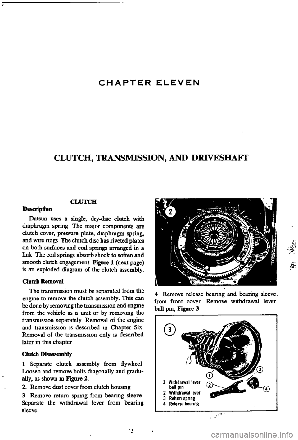
Figure
2
2
Remove
dust
cover
from
clutch
housmg
3
Remove
return
spnng
from
beanng
sleeve
Separate
the
Withdrawal
lever
from
bearing
sleeve
w
1
4
Remove
release
bearmg
and
bearing
sleeve
from
front
cover
Remove
wIthdrawal
lever
ball
pm
Figure
3
CD
1
Withdrawal
lever
ball
pin
2
Withdrawal
lever
3
Return
spnng
4
Release
beanng
4
Page 134 of 252
CLUTCH
TRANSMISSION
AND
DRIVESHAFI
129
scratches
on
the
pressure
plate
may
be
removed
with
crocus
cloth
If
the
source
of
clutch
trouble
IS
still
not
evl
dent
take
the
pressure
plate
and
disc
to
a
compe
tent
garage
to
check
the
pressure
plate
finger
release
height
and
nmout
Never
attempt
to
ad
just
the
fingers
or
dismantle
the
pressure
plate
Without
proper
tools
and
experience
Check
the
release
bearing
by
holdmg
the
Inner
race
and
rotatmg
the
outer
race
With
hght
pres
sure
applied
If
the
bearing
is
rough
or
noisy
replace
it
CAUTION
Never
clean
the
release
bearing
In
solvent
It
IS
prelubriCflted
at
the
fac
tory
Simply
wipe
with
a
Unt
free
cloth
If
the
release
bearing
shows
any
signs
of
loss
of
lubncant
install
a
new
bearing
Replace
the
sleev
lu
SignS
of
wear
are
evident
Clutch
Reassembly
1
Be
sure
your
hands
are
clean
for
the
initIal
assembly
2
Inspect
the
clutch
facings
pressure
plate
and
flywheel
to
be
sure
they
are
free
from
grease
oil
and
other
foreIgn
material
3
TIghtly
fit
release
bearmg
onto
the
bearing
sleeve
When
beanng
IS
mstalled
turn
bearmg
With
a
finger
to
make
sure
It
operates
smoothly
4
Apply
multI
purpose
grease
to
the
bearmg
sleeve
InSIde
groove
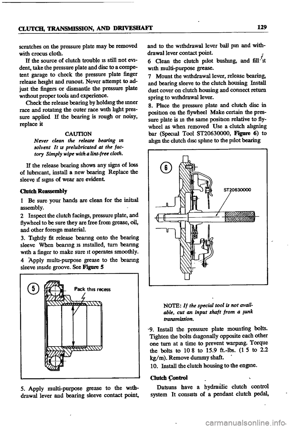
See
Figure
5
CD
Ji
rot
Pac
thiS
r
r
r
1
1i
QI
ecess
5
Apply
multi
purpose
grease
to
the
WIth
drawallever
and
bearing
sleeve
contact
point
and
to
the
Withdrawal
lever
ball
pm
and
with
drawallever
contact
point
f
6
Clean
the
clutch
pllot
bushmg
and
fill
It
With
multi
purpose
grease
7
Mount
the
WithdraWal
lever
release
bearing
and
bearing
sleeve
to
the
clutch
housing
Install
dust
cover
on
clutch
housing
and
connect
return
spring
to
WithdraWal
lever
8
Place
the
pressure
plate
and
clutch
disc
in
positIon
on
the
flywheel
Make
certain
the
pres
sure
plate
is
In
the
same
positIon
relative
to
fly
wheel
as
when
removed
Use
a
clutch
alIgning
bar
Special
Tool
ST20630000
FIgDfe
6
to
alIgn
the
clutch
dISc
splIne
to
the
pllot
bearing
CD
NOTE
If
the
special
tool
is
not
avail
able
cut
an
input
shaft
from
a
Junk
transmission
9
Install
the
pressure
plate
mounting
bolts
Tighten
the
bolts
dIagonally
opposite
each
other
one
turn
at
a
time
to
prevent
warpmg
Torque
the
bolts
to
10
8
to
15
9
ft
lbs
1
5
to
2
2
kg
m
Remove
durmny
shaft
10
Install
the
clutch
housing
to
the
engme
Clutch
ntrol
Datsuns
have
a
hydraulic
clutch
control
system
It
consISts
of
a
pendant
clutch
pedal
Page 138 of 252
CLUTCH
TRANSMISSION
AND
DRlVESIIAFI
133
C
8
Q@J
@
C
Operating
Cylinder
Reassembly
1
Soak
pISton
cup
m
brake
flUid
and
Install
It
In
the
same
pOSitIOn
as
before
removal
2
Apply
brake
flUid
to
the
cylInder
and
pIston
before
mstalImg
piston
3
Replace
all
parts
m
the
reverse
order
of
removal
Operating
Cylinder
Installation
1
RemstallatIon
IS
the
reverse
of
removal
2
Bleed
aIr
from
the
hydraulIc
system
3
Adjust
the
pushrod
so
that
withdrawal
lever
end
play
IS
0
0787
to
0
1181
In
2
0
to
3
Omm
Procedures
for
the
adjustment
are
given
below
WITHDRAWAL
LEVER
AD
JUSTMENT
Correct
adjustment
of
the
clutch
withdrawal
lever
IS
essentIal
InsufficIent
free
travel
between
the
release
bearmg
and
dIaphragm
fingers
can
cause
the
clutch
to
slIp
ExceSSIve
free
travel
can
prevent
full
dISengagement
of
the
clutch
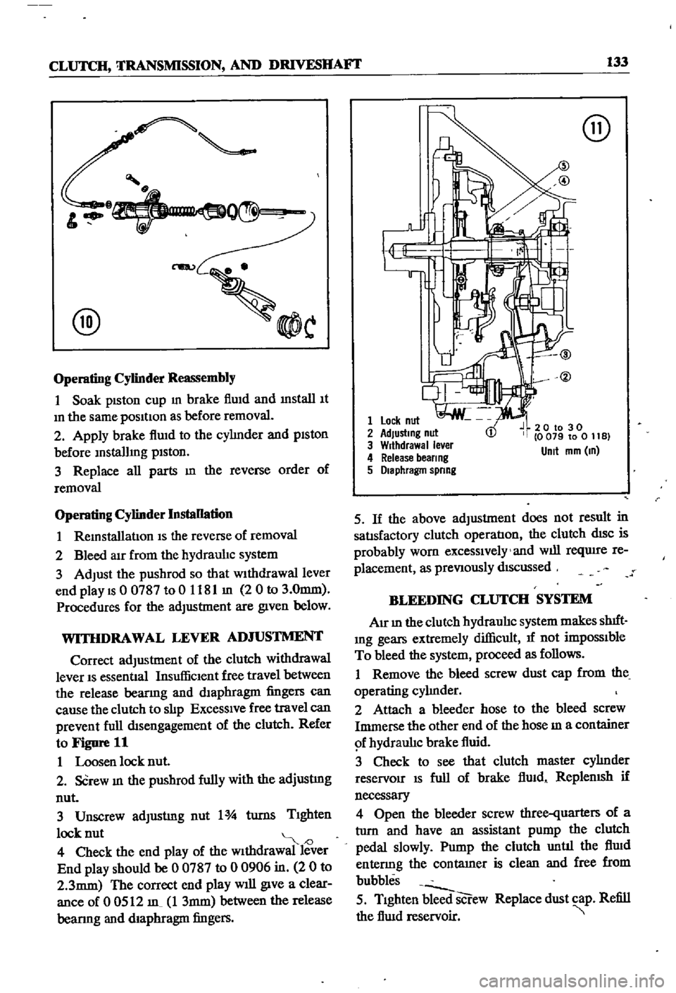
Refer
to
Figure
11
1
Loosen
lock
nut
2
SCrew
In
the
pushrod
fully
with
the
adjustmg
nut
3
Unscrew
adJustmg
nut
1
turns
TIghten
lock
nut
J
4
Check
the
end
play
of
the
wIthdrawal
lever
End
play
should
be
0
0787
to
0
0906
in
2
0
to
2
3mm
The
correct
end
play
will
give
a
clear
ance
of
0
0512
m
1
3mm
between
the
release
bearmg
and
diaphragm
fingers
@
1
Lock
nut
2
AdJustmg
nut
3
Wrthdrawal
ever
4
Release
beer
ng
5
Diaphragm
spnng
20
to
30
0
079
to
0
11
B
Unit
mm
m
5
If
the
above
adjustment
does
not
result
in
satIsfactory
clutch
operatIon
the
clutch
dISC
is
probably
worn
excessIvely
and
will
reqUire
re
placement
as
preVIously
dIScussed
BLEEDING
CLUTCH
SYSTEM
AIr
In
the
clutch
hydraulIc
system
makes
shIft
Ing
gears
extremely
difficult
1f
not
impOSSIble
To
bleed
the
system
proceed
as
follows
1
Remove
the
bleed
screw
dust
cap
from
the
operating
cylInder
2
Attach
a
bleeder
hose
to
the
bleed
screw
Immerse
the
other
end
of
the
hose
m
a
container
f
hydraulIc
brake
fluid
3
Check
to
see
that
clutch
master
cylInder
reservoir
IS
full
of
brake
flUid
ReplenISh
if
necessary
4
Open
the
bleeder
screw
three
quarters
of
a
tlIrn
and
have
an
assistant
pump
the
clutch
pedal
slowly
Pump
the
clutch
until
the
flUid
entenng
the
contatner
is
clean
and
free
from
bubbles
5
TIghten
bleed
screw
Replace
dust
cap
Refill
the
flUid
reservoir
Page 139 of 252
134
CHAPTER
ELEVEN
CLUTCH
SERVICE
DATA
AND
SPECIF1CATIONS
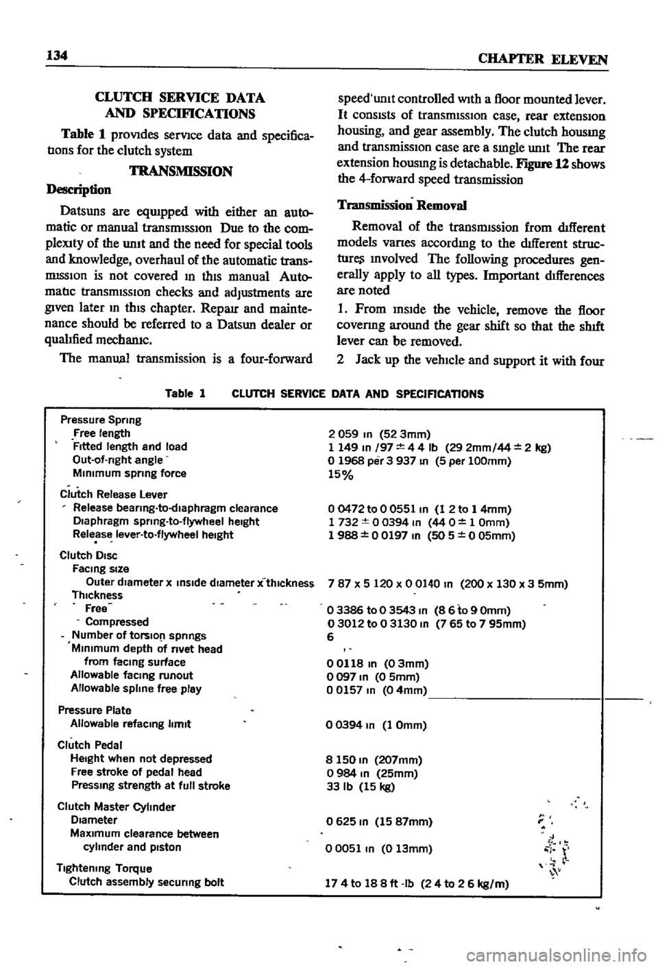
Table
1
proVIdes
serVIce
data
and
specifica
tIons
for
the
clutch
system
TRANSMISSION
Description
Datsuns
are
eqUIpped
with
either
an
auto
matic
or
manual
transrmSSIOn
Due
to
the
com
pleXity
of
the
unIt
and
the
need
for
special
tools
and
knowledge
overhaul
of
the
automatic
trans
mISSIon
is
not
covered
In
thIS
manual
Auto
matIc
transmISSIOn
checks
and
adjustments
are
given
later
m
thIS
chapter
Reparr
and
mainte
nance
should
be
referred
to
a
Datsun
dealer
or
qualIfied
mechamc
The
manual
transmission
is
a
four
forward
Table
1
speed
unlt
controlled
With
a
floor
mounted
lever
It
consIsts
of
transrmSSIOn
case
rear
extensIOn
housing
and
gear
assembly
The
clutch
housmg
and
transmissIOn
case
are
a
sIngle
unIt
The
rear
extension
housmg
is
detachable
Figure
12
shows
the
4
forward
speed
transmission
Transmission
Removal
Removal
of
the
transmIssion
from
dIfferent
models
Varles
accordmg
to
the
dIfferent
struc
ture
Involved
The
following
procedures
gen
erally
apply
to
all
types
Important
dIfferences
are
noted
1
Prom
InsIde
the
vehicle
remove
the
floor
covenng
around
the
gear
shift
so
that
the
shIft
lever
can
be
removed
2
Jack
up
the
vehIcle
and
support
it
with
four
CLUTCH
SERVICE
DATA
AND
SPECIFICATIONS
Pressure
Spring
Free
length
Fitted
length
and
load
Out
of
rlght
angle
MInimum
sprmg
force
Clutch
Release
Lever
Release
bearlng
to
dlaphragm
clearance
Diaphragm
sprlng
to
flywheel
height
Release
lever
to
flywheel
height
Clutch
DISC
FaCing
size
Outer
dIameter
x
inSide
diameter
x
thlckness
Thickness
Free
Compressed
Number
of
tOrslO
1
springs
Minimum
depth
of
rivet
head
from
faCing
surface
Allowable
facmg
runout
Allowable
spline
free
play
Pressure
Plate
Allowable
refacmg
limit
Clutch
Pedal
Height
when
not
depressed
Free
stroke
of
pedal
head
Pressmg
strength
at
full
stroke
Clutch
Master
Cylinder
Diameter
MaXimum
clearance
between
cylinder
and
pIston
Tightening
Torque
Clutch
assembly
securing
bolt
2
059
In
52
3mm
1
149
In
197
4
4
Ib
29
2mm
44
2
kg
o
1968
per
3
937
In
5
per
100mm
15
00472
to
0
0551
In
1
2
to
1
4mm
1732
0
0394
m
44
O
1
Omm
1
988
0
0197
In
505
0
05mm
787
X
5
120
x
0
0140
In
200
x
130
x
3
5mm
o
3386
to
0
3543
m
8
6
to
9
Omm
03012
to
0
3130
m
765
to
7
95mm
6
00118
In
03mm
o
097
In
0
5mm
00157
m
04mm
o
0394
In
1
Omm
8
150
m
207mm
o
984
m
25mm
33
Ib
15
kg
0625
m
15
87mm
00051
m
0
13mm
J
i
r
174
to
188ft
Ib
24
to
2
6
kg
m
Page 140 of 252
CLUTCH
TRANSMISSION
AND
DRIVESIIAFI
135
stands
If
possible
the
use
of
an
open
pit
or
hydraulIc
hOISt
IS
recommended
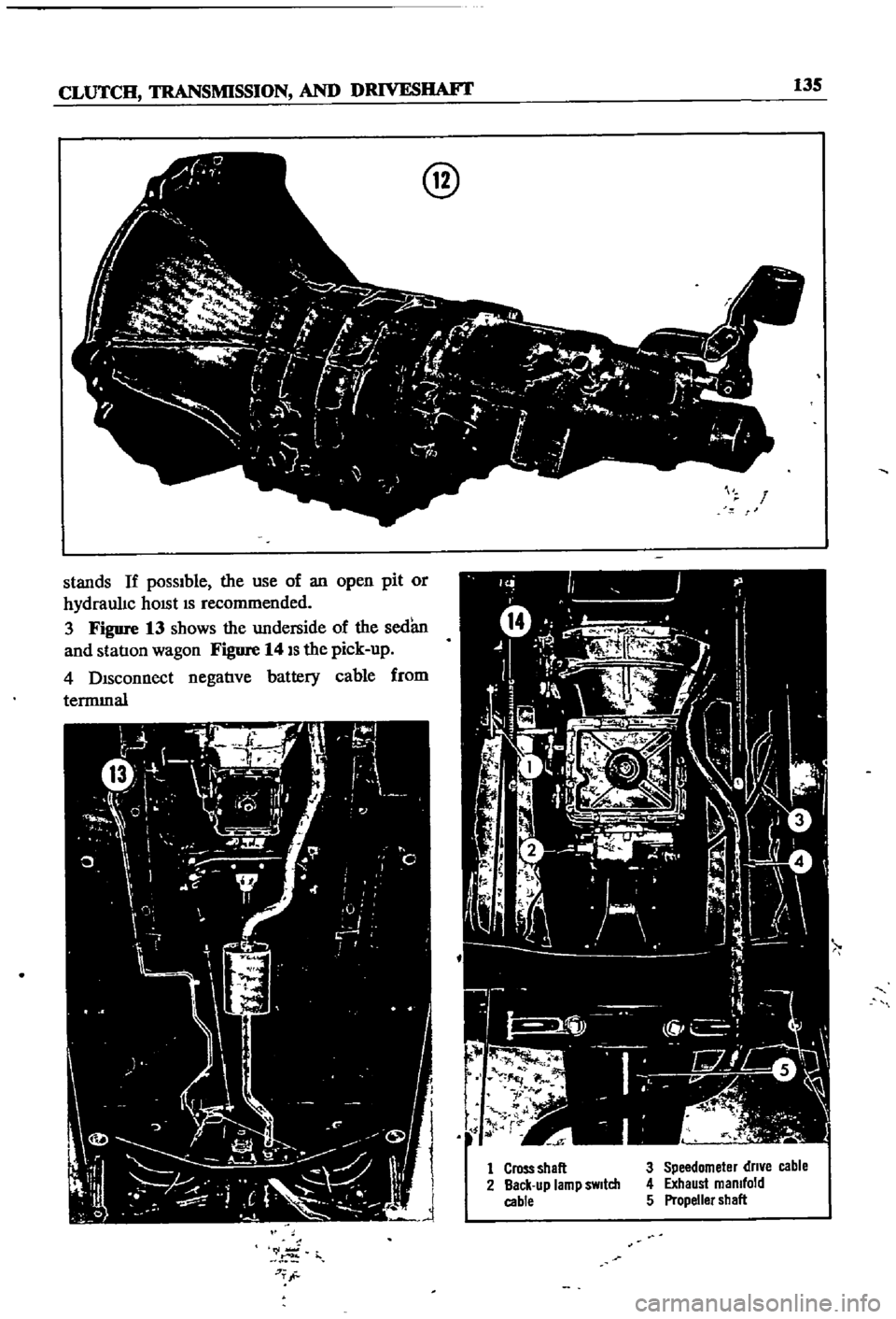
3
Figure
13
shows
the
underside
of
the
sedan
and
statIon
wagon
Figure
14
IS
the
pick
up
4
DIsconnect
negatIve
battery
cable
from
termInal
r
j
7T
@
r
1
Cross
shall
2
Back
up
lamp
sWitch
cable
3
Speedometer
dn
e
cable
4
Exhaust
manifold
5
Propeller
shall