1968 DATSUN 510 ABS
[x] Cancel search: ABSPage 5 of 252
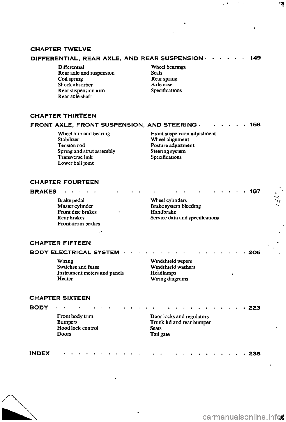
CHAPTER
TWELVE
DIFFERENTIAL
REAR
AXLE
AND
REAR
SUSPENSION
149
DIfferentIal
Rear
axle
and
suspension
Codspnng
Shock
absorber
Rear
suspensIOn
arm
Rear
axle
shaft
Wheel
beanngs
Seals
Rear
spnng
Axle
case
SpecificatIons
CHAPTER
THIRTEEN
FRONT
AXLE
FRONT
SUSPENSION
AND
STEERING
168
Wheel
hub
and
bearmg
StabilIzer
TenSion
rod
Spnng
and
strut
assembly
Transverse
lInk
Lower
ball
Jomt
Front
suspension
adjustment
Wheel
alignment
Posture
adJustment
Steenng
system
SpeCificatIons
CHAPTER
FOURTEEN
BRAKES
187
Brake
pedal
Master
cylInder
Front
diSC
brakes
Rear
brakes
Front
drum
brakes
Wheel
cylInders
Brake
system
bleedIng
Handbrake
Service
data
and
speCificatIons
CHAPTER
FIFTEEN
BODY
ELECTRICAL
SYSTEM
Wmng
SWitches
and
fuses
Instrument
meters
and
panels
Heater
205
Wmdshleld
wipers
Wmdslueld
washers
Headlamps
WIrIng
diagrams
CHAPTER
SIXTEEN
BODY
223
Front
body
trIm
Bumpers
Hood
lock
control
Doors
Door
locks
and
regulators
Trunk
lId
and
rear
bumper
Seats
Tad
gate
INDEX
235
I
Page 10 of 252
GENERAL
INFORMATION
5
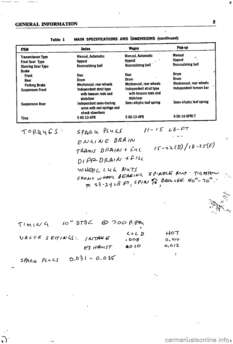
Table
1
MAIN
SPECIFICATIONS
AND
DIMENSIONS
continued
Suspension
Rear
Sedan
Wagon
Pick
up
Manual
Automatic
Manual
Automatic
Manual
HypoJd
Hypoid
Hypold
ReCIrculating
ball
ReCIrculating
ball
ReCirculating
ball
DIsc
DIsc
Drum
Drum
Drum
Drum
Mechanical
rear
wheels
Mechanical
rear
wheels
Mechanical
rear
wheels
Independent
strut
type
Independent
strut
type
Independent
torsion
bar
with
tension
rods
and
with
tension
rods
and
stabilizer
stabilIZer
Independent
semi
trailing
Semi
elliptiC
leaf
spring
Semi
elliptic
leaf
spnng
arms
wrtII
coli
springs
and
shock
absorbers
5
6O
13
4PR
5
6O
13
4PR
600
14
6PRLT
ITEM
Transmission
Type
Final
Gear
Type
Steering
Gear
Type
Brake
Front
Rear
Parking
Brake
Suspension
Front
Tires
6
2
Q
1
C
S
PA
l
PlLlU
EN
4
1
AJ
E
Dt7
A
1
1
1
2
A
ru
r
f
f
A
I
III
r
c
o
I
pP
D
LA
I
tV
r
IL
c
W
L
L
l
G
ftiv
TJ
dE
IJ
S
prlc
I
u
F
l
e
p
f
vi
Ii
ftl
1
3
l
1t
J
p7
5
PrlV
B4dc
u
11
1
S
t
f
PT
f
L
UJ
ff
zr
F
T
ff
lfo
1oo
4
t
M
0
IY
AJ
to
BTOL
@
OD
2
lP
S
PAtl
pI
c
5
IN
G
ex
Sf
0103
I
D
0
3
O
j
oo
0
0
0
to
l
c
o
0
0
2
JP
t
UE
SEIT
A
C
1
J
Page 76 of 252
FUEL
SYSTEM
71
Dash
Pot
Adjustment
The
adjustment
of
the
dash
pot
IS
done
by
warmmg
up
the
engme
properly
and
checkIng
If
the
throttle
lever
touches
th
dash
pot
stem
as
the
engine
reaches
1
800
and
2
000
rpm
under
no
load
conditIons
Proper
contact
between
the
throttle
lever
and
the
dash
pot
stem
produces
a
normal
dash
pot
performance
Should
a
normal
mcrease
m
engme
speed
not
occur
adjust
the
dash
pot
as
follows
1
Loosen
the
dash
pot
locknuts
2
Rotate
the
dash
pot
nght
and
then
left
3
Adjust
the
dash
pot
so
that
the
throttle
lever
hIts
the
stem
between
1
800
and
2
000
rpm
4
Fasten
the
lock
nuts
securely
5
The
clearance
between
the
throttle
valve
and
the
throttle
chamber
wall
should
be
0
0709
m
0
8mm
or
10
degrees
In
throttle
valve
angle
MAJOR
CARBURETOR
SERVICE
PROCEDURES
A
carburetor
m
good
operatIng
condition
will
delIver
the
pr
per
gasolme
and
aIr
ratIos
for
all
engme
runnmg
speeds
A
gradual
declme
In
smoothness
response
and
power
Will
occur
as
the
carburetor
slIps
from
adjustment
and
Its
delI
cate
parts
become
dirty
and
worn
Overhaul
should
only
be
attempted
by
an
expenenced
mechanic
Accurate
calIbratIon
of
passages
and
dIS
charge
hole
reqUIre
that
extreme
care
be
taken
In
dISassembly
cleanmg
and
reassembly
Use
only
a
hIgh
grade
carburetor
cleaner
and
com
pressed
arr
to
clean
parts
and
passages
Never
use
wire
or
other
pOInted
Instruments
for
clean
ing
CalIbratIon
of
the
carburetor
will
be
af
fected
The
procedures
below
are
generally
true
for
all
models
As
an
aId
Figures
13
and
14
are
typIcal
examples
of
the
carburetors
used
Carburetor
Removal
1
Remove
the
au
cleaner
by
dIsconnectIng
all
hoses
attached
to
It
remoVmg
the
two
bolts
holdmg
the
aIr
cleaner
to
the
support
and
loos
enmg
the
band
bolt
at
the
base
of
the
aIr
cleaner
2
DIsconnect
fuellme
vacuum
Ime
and
choke
wire
u
eqUIpped
from
the
carburetor
3
Remove
the
throttle
lever
4
Remove
four
nuts
and
washers
holdmg
car
buretor
to
manIfold
5
Lift
carburetor
off
of
manuold
6
Remove
and
dIscard
carburetor
to
manuold
gasket
7
Place
carburetor
on
clean
workbench
Carburetor
Disassembly
1
The
maIn
Jets
slow
Jets
and
needle
valves
on
both
the
pnmary
and
secondary
systenIS
are
accessIble
from
outsIde
the
carburetor
Refer
to
FIgures
13
and
14
for
locatI
n
2
The
choke
chamber
can
be
detached
by
re
mOVIng
the
connectIng
rod
pump
connectIng
rod
return
sprmg
stop
pm
and
the
set
screws
I
that
hold
It
in
place
3
The
pnmary
and
secondary
emulSIon
tubes
can
be
disassembled
by
remOVIng
the
mam
air
bleeds
on
the
respectIve
SIdes
4
To
check
the
accelerator
pump
remove
the
cylInder
cover
Be
careful
not
to
lose
the
return
spnng
and
Inlet
valve
at
the
lower
part
of
the
pIston
durmg
dIsassembly
5
Detach
the
throttle
chamber
from
the
float
chamber
by
remOVIng
the
rod
lInkIng
the
dia
phragm
WIth
the
secondary
throttle
valve
and
the
four
screws
that
hold
It
However
It
IS
preferable
to
leave
the
throttle
valve
mtact
unless
absolutely
reqUired
If
It
IS
necessary
to
dlS
assemble
the
valve
It
should
be
Installed
so
that
the
secondary
throttle
valve
will
be
gap
free
OtherwIse
stable
Idle
and
good
slow
speed
performance
will
suffer
is
To
check
the
float
the
float
chamber
cover
must
be
removed
I
7
The
dIaphragm
IS
dIsassembled
by
removing
the
set
screws
holdmg
the
dIaphragm
chamber
cover
In
reassemblIng
the
diaphragm
be
careful
not
to
turn
the
edge
of
the
dIaphragm
up
8
In
dlsassemblmg
and
reassembling
the
mter
lockIng
lInks
take
care
so
that
each
lInkage
has
a
smooth
actIon
and
that
parts
are
not
forced
mto
pOSItIon
9
For
vehIcles
equipped
With
an
automatIc
choke
remove
the
brmetal
case
by
releasmg
the
set
screws
The
bimetal
1l
extremely
senSItIve
Page 132 of 252
CHAPTER
ELEVEN
CLUTCH
TRANSMISSION
AND
DRIVESHAFf
CLUTCH
i
es
ription
Datsun
uses
a
single
dry
dtsc
clutch
with
dIaphragm
spring
The
major
components
are
clutch
cover
pressure
plate
dIaphragm
spring
and
WIre
nngs
The
clutch
dISC
has
riveted
plates
on
both
surfaces
and
coll
spnngs
arranged
in
a
link
The
coll
springs
absorb
shock
to
soften
and
smooth
clutch
engagement
Figure
1
next
page
is
an
exploded
diagram
of
the
clutch
assembly
Clutch
Removal
The
transmIssion
must
be
separated
from
the
engme
to
remove
tlte
clutch
assembly
This
can
be
done
by
removmg
the
transmISSIon
and
engme
from
the
vehicle
as
a
umt
or
by
remoVIng
the
transmiSSIon
separately
Removal
of
the
engine
and
transmissIOn
IS
descnbed
In
Chapter
Six
Removal
of
the
transmISSIon
only
IS
descnbed
later
in
tills
chapter
Outcb
Disassembly
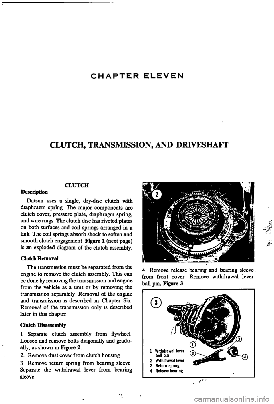
1
Separate
clutch
assembly
from
flywheel
Loosen
and
remove
bolts
dIagonally
and
gradu
ally
as
shown
m
Figure
2
2
Remove
dust
cover
from
clutch
housmg
3
Remove
return
spnng
from
beanng
sleeve
Separate
the
Withdrawal
lever
from
bearing
sleeve
w
1
4
Remove
release
bearmg
and
bearing
sleeve
from
front
cover
Remove
wIthdrawal
lever
ball
pm
Figure
3
CD
1
Withdrawal
lever
ball
pin
2
Withdrawal
lever
3
Return
spnng
4
Release
beanng
4
Page 156 of 252

DIFFERENTIAL
REAR
AXLE
AND
REAR
SUSPENSION
151
4
Lower
the
Jack
and
r
move
dIfferentIal
from
rear
of
vehIcle
See
Figure
4
After
removal
sup
port
suspensIon
member
wIth
a
stand
to
prevent
distortlon
and
damage
to
the
Insulators
Differential
Inspection
Sedan
The
followmg
mspectIon
can
be
done
WIthout
disassembly
of
the
dIfferential
If
abnormalitIes
or
damage
eXiSts
refer
further
servIce
and
reparr
to
your
dealer
1
Check
the
tooth
contact
pattern
With
lead
oXide
at
two
or
three
pomts
after
removmg
rear
cover
Refer
to
Figure
5
which
shows
the
cor
rect
contact
pattern
If
the
contact
pattern
IS
m
correct
dIsassembly
and
adjustment
of
dIffer
entlalls
reqUIred
CD
TOE
HEEL
DRIVE
SIDE
HEEL
COAST
SIDE
2
Use
a
dIal
mdtcator
to
measure
backlash
be
tween
the
dnve
gear
and
pmIOn
Backlash
should
be
0
0039
to
0
0079
m
0
10
to
o
20mm
Check
all
gear
teeth
for
damage
and
cracks
3
Check
runout
at
the
rear
of
the
dnve
gear
If
the
tooth
contact
pattern
or
backlash
IS
ab
normal
Runout
should
be
less
than
00031
m
0
08mm
See
Figure
6
4
Rotate
the
gears
and
lIsten
for
SignS
of
de
fective
bearmgs
If
noises
are
eVIdent
the
dIf
ferential
must
be
dIsassembled
and
repaired
CD
Diflerentiallnstallation
Sedan
1
Mount
the
dIfferentIal
assembly
to
the
rear
suspensIOn
member
2
FIt
the
dIfferentIal
mountlng
member
to
the
fittmg
hole
by
pushIng
It
forward
with
a
bar
Torque
the
nuts
to
61
ft
lb
8
5
kg
m
3
Install
axle
dnve
shafts
dnve
shaft
and
handbrake
rear
cable
REAR
AXLE
AND
SUSPENSION
SEDAN
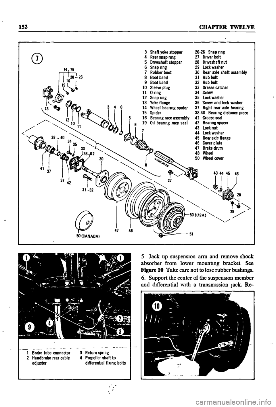
Figure
7
and
Figure
8
page
153
are
ex
ploded
dIagrams
of
the
sedan
rear
axle
and
suspensIOn
The
fully
independent
rear
suspen
SIon
IS
a
semI
traIlIng
arm
deSIgn
With
a
sus
penSIOn
member
suspensIOn
arms
coIl
spnngs
and
hydraulIc
shock
absorbers
The
wheel
bearings
are
lIfetime
lubncated
Rear
Axle
and
Suspension
Removal
Sedan
1
Jack
up
the
rear
of
the
veh1cle
and
support
It
on
stands
2
Remove
wheels
3
Refer
to
Figure
9
and
dtsconnect
handbrake
lInkage
and
rerum
sprmg
Remove
tall
pIpe
and
muffler
4
DISconnect
brake
hose
from
brake
tube
Re
move
four
bolts
holdmg
dnve
shaft
to
dIf
ferential
Lower
dnve
shaft
gently
to
ground
Page 157 of 252
152
CHAPTER
TWELVE
3
Shall
yoke
stopper
0
4
Rear
snap
nng
J
5
Dn
eshall
stopper
6
Snap
nng
7
Rubber
boot
8
Boot
band
9
Boot
band
10
Slee
e
plug
11
O
nng
12
Snap
nng
13
Yoke
flange
3
4
6
14
Whee
beanng
spIder
15
Spider
12
5
16
Beanng
race
assembly
j
50
CANADA
47
AtO
C
J
ty
9
1
Y
4
i
l
A
I
ii
1
o
l
J
Il
h
o
20
J
I
1
Brake
tube
connector
2
Handbrake
rear
cable
adjuster
3
Return
spnng
4
Propeller
shall
to
dlfferenballixlng
bolts
20
26
Snap
nng
27
Dn
er
bolt
28
Onveshall
nut
29
Lock
washer
30
Rear
axle
shall
assembly
31
Hub
bolt
32
Hub
bolt
33
Grease
catcher
34
Screw
35
Lock
washer
36
Screw
and
Ioc
l
washer
37
Right
rear
axle
beanng
38
40
Beanng
distance
piece
41
Grease
seal
42
Beanng
spacer
43
Lock
nut
44
lock
washer
45
Rear
axle
flange
46
Cover
plate
47
Brake
drum
48
Wheel
50
Wheel
oover
43
44
45
46
51
5
Jack
up
suspenSIon
arm
and
remove
shock
absorber
from
lower
mountlng
bracket
See
Figure
10
Take
care
not
to
lose
rubber
bushmgs
6
Support
the
center
of
the
suspensIon
member
and
dIfferential
With
a
transmISsion
Jack
Re
Page 159 of 252
154
CHAPTER
tWELVE
move
two
nuts
attachmg
dtfferenual
suspension
member
to
the
body
7
Gently
lower
the
suspension
assembly
from
the
body
by
10wermg
the
jack
Support
the
suspension
so
It
does
not
fall
off
of
the
Jack
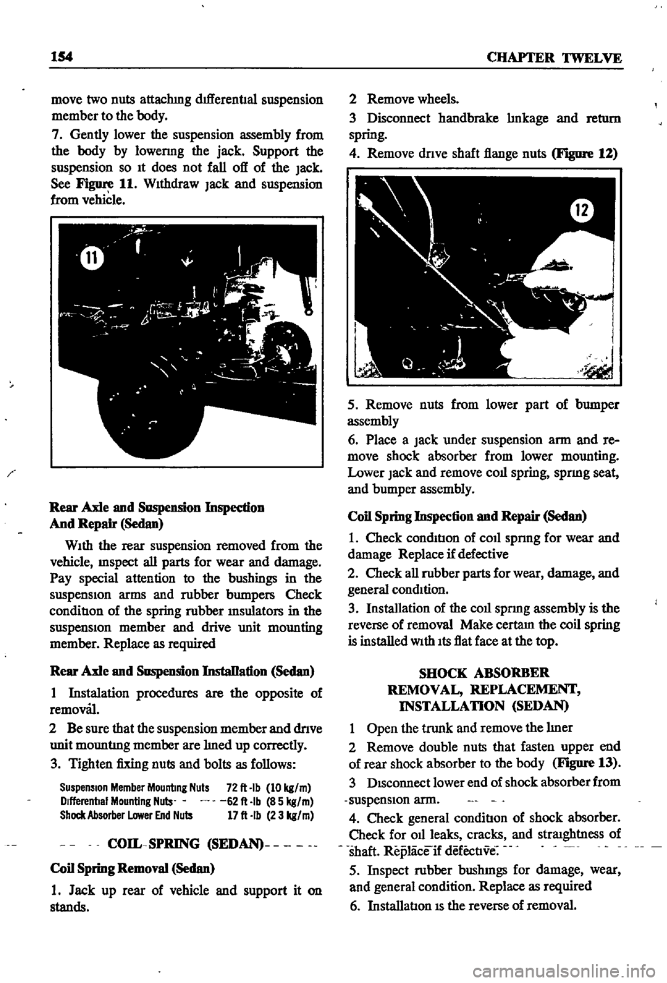
See
Figure
11
WIthdraw
Jack
and
suspension
from
vehicle
Rear
Axle
and
Suspension
Inspedion
And
Repair
Sedan
WIth
the
rear
suspension
removed
from
the
vehicle
InSpect
all
parts
for
wear
and
damage
Pay
special
attention
to
the
bushings
in
the
suspensIon
arms
and
robber
bumpers
Check
conditIon
of
the
spring
robber
msulators
in
the
suspensIOn
member
and
drive
unit
mounting
member
Replace
as
required
Rear
Axle
and
Suspension
InstaDation
Sedan
1
Instalation
procedures
are
the
opposite
of
removal
2
Be
sure
that
the
suspension
member
and
dnve
unit
mountmg
member
are
med
up
correctly
3
Tighten
fixing
nuts
and
bolts
as
follows
Suspension
Member
Mounting
Nuts
72
It
Ib
10
kg
m
Dlfferenbal
Mounting
Nuls
62
It
Ib
85
kg
m
Shock
Absorber
Lower
End
Nuts
17
It
Ib
23
kg
m
COIL
SPRING
SEDAN
Coil
Spring
Removal
Sedan
1
Jack
up
rear
of
vehicle
and
support
it
on
stands
2
Remove
wheels
3
Disconnect
handbrake
mkage
and
retl1rn
spring
4
Remove
dnve
shaft
flange
nuts
Figure
12
5
Remove
nuts
from
lower
part
of
bumper
assembly
6
Place
a
Jack
under
suspension
arm
and
re
move
shock
absorber
from
lower
mounting
Lower
Jack
and
remove
coll
spring
spnng
seat
and
bumper
assembly
Coil
Spring
Inspection
and
Repair
Sedan
1
Check
condItIon
of
coll
sprmg
for
wear
and
damage
Replace
if
defective
2
Check
all
robber
parts
for
wear
damage
and
general
condItion
3
Installation
of
the
coll
spnng
assembly
is
the
reverse
of
removal
Make
certam
the
coil
spring
is
installed
With
Its
flat
face
at
the
top
SHOCK
ABSORBER
REMOVAL
REPLACEMENT
INSTALLATION
SEDAN
1
Open
the
trunk
and
remove
the
mer
2
Remove
double
nuts
that
fasten
upper
end
of
rear
shock
absorber
to
the
body
Figure
13
3
DIsconnect
lower
end
of
shock
absorber
from
suspensIon
arm
4
Check
general
conditIon
of
shock
absorber
Check
for
011
leaks
cracks
and
straIghtness
of
shaft
Replaceif
defectIve
5
Inspect
robber
bushmgs
for
damage
wear
and
general
condition
Replace
as
required
6
InstallatIon
IS
the
reverse
of
removal
Page 160 of 252
DIFFERENTIAL
REAR
AXLE
AND
REAR
SUSPENSION
155
i
I
I
I
REAR
SUSPENSION
ARM
SEDAN
Rear
Suspension
Arm
Removal
Sedan
1
Jack
up
the
rear
of
the
vehIcle
and
support
It
on
stands
2
Remove
wheel
and
brake
drum
3
DIsconnect
dnve
shaft
from
axle
shaft
4
Remove
handbrake
cable
from
lever
attached
to
wheel
cylInder
5
Plug
brake
tube
to
prevent
loss
of
brake
flwd
6
Remove
wheel
beanng
lock
nut
rear
axle
shaft
wheel
beanngs
and
OIl
seal
Remove
rear
brake
assembly
from
suspensIOn
arm
7
Place
Jack
under
suspenSIon
arm
remove
shock
absorber
from
lower
bracket
lower
Jack
gradually
remove
coll
spnng
spnng
seat
and
bumper
assembly
8
Remove
two
bolts
secunng
suspensIOn
arm
to
suspensIOn
member
and
remove
suspensIOn
arm
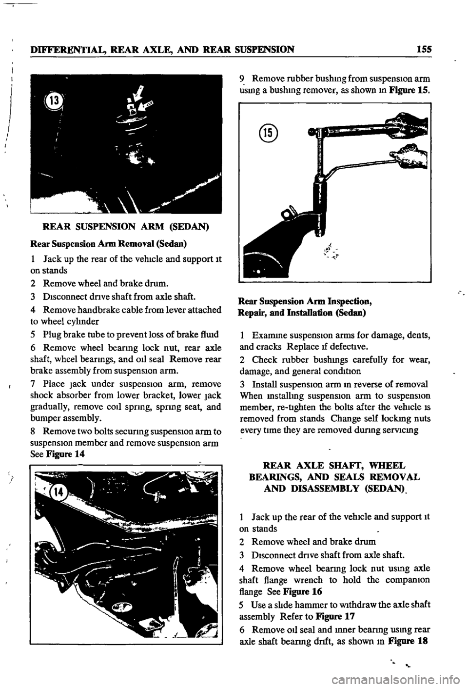
See
Figure
14
9
Remove
rubber
bushmg
from
suspensIon
arm
usmg
a
bushmg
remover
as
shown
In
Figure
15
@
Rear
SllSpension
Arm
Inspection
Repair
and
Installation
Sedan
1
Examme
suspensIOn
arms
for
damage
dents
and
cracks
Replace
tf
defectIve
2
Check
rubber
bushmgs
carefully
for
wear
damage
and
general
condItIon
3
Install
suspensIOn
arm
m
reverse
of
removal
When
Installmg
suspensIOn
arm
to
suspensIOn
member
re
tIghten
the
bolts
after
the
vehIcle
IS
removed
from
stands
Change
self
lockmg
nuts
every
tIme
they
are
removed
dunng
semcmg
REAR
AXLE
SHAFf
WHEEL
BEARINGS
AND
SEALS
REMOVAL
AND
DISASSEMBLY
SEDAN
1
Jack
up
the
rear
of
the
vehIcle
and
support
It
on
stands
2
Remove
wheel
and
brake
drum
3
DIsconnect
dnve
shaft
from
axle
shaft
4
Remove
wheel
bearmg
lock
nut
usmg
axle
shaft
flange
wrench
to
hold
the
companIOn
flange
See
Figure
16
5
Use
a
slIde
hammer
to
Withdraw
the
axle
shaft
assembly
Refer
to
Figure
17
6
Remove
011
seal
and
Inner
bearmg
usmg
rear
axle
shaft
bearmg
dnft
as
shown
In
Figure
18