1968 DATSUN 510 alternator belt
[x] Cancel search: alternator beltPage 12 of 252

PERIODIC
MAINTENANCE
7
Table
1
ENGINE
LUBRICATION
AND
MAINTENANCE
FREQUENCY
EVERY
E
E
E
E
E
E
E
Eo
00
00
00
00
00
00
00
gq
00
00
00
NO
t
r61li
0
CD
Check
engine
011
level
top
up
If
required
X
Change
engine
011
X
Lubricate
carburetor
hnkage
X
Lubricate
distributor
rotor
shaft
and
ann
shaft
X
Apply
grease
to
distributor
cam
heel
X
Check
radiator
coolant
level
X
Change
radIator
coolant
X
Change
radiator
coolant
additive
X
Check
battery
electrolyte
level
X
Check
specific
gravity
of
battery
X
Check
engine
starting
exhaust
color
X
Tighten
cyhnder
head
manifolds
and
pipe
flanges
X
Adjust
valve
clearance
X
Check
Ignition
timing
X
Tighten
carburetor
fittings
X
Check
fan
belt
tension
X
Check
for
011
pan
leakage
X
Tighten
engine
mounts
X
Check
fuel
strainer
X
Replace
fuel
strainer
X
Check
for
fuel
leaks
X
Replace
011
filter
X
Check
spark
plugs
X
Replace
spark
plugs
X
Check
dlstnbutor
cap
rotor
and
POints
X
Adjust
engine
Idle
speed
X
Check
air
cleaner
fittings
X
Clean
011
filler
cap
X
Clean
battery
cables
and
terminals
X
Check
alternator
and
voltage
regulator
function
X
Check
starter
motor
function
X
Replace
aIr
cleaner
element
X
Check
fuel
pump
function
X
Check
cyhnder
compressIon
X
Clean
carburetor
Jets
and
float
chamber
X
Check
dlstnbutor
condenser
X
Check
crankcase
ventilation
control
valve
X
Page 17 of 252

12
CHAPTER
THREE
13
IMPROPER
IDLE
MIXTURE
Roats
slowly
between
13
17
14
SMALl
SPARK
GAP
or
DEFECTIVE
POINTS
Slight
float
between
14
16
ignItIOn
switch
If
the
starter
still
fails
to
crank
properly
remove
the
starter
and
test
it
2
Starter
turns
but
does
not
engage
with
engine
This
trouble
is
usually
a
defective
pInion
or
sole
noid
shlfting
fork
It
may
also
be
that
the
teeth
on
the
pInion
flywheel
ring
gear
or
both
are
worn
down
too
far
to
engage
properly
3
Starter
engages
but
will
not
dISengage
when
IgmtlOn
switch
IS
released
TIns
trouble
is
usually
caused
by
a
sticking
sole
nOid
but
occasionally
the
pmlOn
can
jam
on
the
flywheel
With
manual
transmissions
the
pinion
can
be
temporanly
freed
by
rockmg
the
car
in
high
gear
Naturally
this
IS
not
poSSible
in
auto
matics
the
starter
must
be
removed
4
Loud
grinding
noISes
when
starter
runs
TIns
usually
means
the
teeth
on
the
pinion
and
or
flywheel
are
not
meshing
properly
It
may
also
mean
the
over
running
clutch
IS
broken
In
the
first
case
remove
the
starter
and
examine
the
gear
teeth
In
the
latter
remove
the
starter
and
replace
the
pmion
dnve
assembly
CHARGING
SYSTEM
Charging
system
troubles
may
be
in
the
alter
nator
voltage
regulator
or
fan
belt
The
follow
ing
symptoms
are
typical
1
Alternator
warning
lamp
does
not
come
on
when
IgmtlOn
is
turned
on
This
may
indicate
a
defective
ignition
switch
battery
voltage
regulator
or
lamp
Frrst
try
to
15
HEAD
GASKET
LEAK
Roats
between
5
19
16
RESTRICTm
EXHAUST
SYSTEM
Normal
when
first
started
Drops
to
0
as
rpm
Increases
May
eventually
rrse
to
about
16
start
the
car
If
it
doesn
t
start
check
the
igllltlon
sWitch
and
battery
If
the
car
starts
find
the
voltage
regulator
and
disconnect
the
wlute
red
Wire
this
is
the
lamp
wire
Ground
the
wire
If
the
lamp
hghts
the
voltage
regulator
is
defective
not
properly
grounded
try
tightening
the
mounting
screws
or
the
alternator
brushes
are
not
contactmg
the
commutator
If
the
lamp
does
not
light
when
the
wire
IS
grounded
the
lamp
is
probably
burned
out
replace
It
2
Alternator
warning
lamp
comes
on
and
stays
on
This
usually
mdicates
that
no
chargmg
is
takmg
place
Frrst
check
the
fan
belt
tension
and
adlust
if
necessary
Check
the
battery
condition
with
the
hydrometer
and
check
all
electrical
connec
tions
m
the
chargmg
system
Fmally
isolate
the
trouble
to
the
alternator
or
voltage
regulator
3
Alternator
warmng
lamp
flashes
erratically
This
usually
indicates
the
chargmg
system
is
workmg
intermittently
Check
the
fan
belt
ten
sion
and
all
electncal
connections
m
the
charg
ing
system
Check
alternator
brushes
and
cODlh
tlon
of
the
commutator
4
Baltery
reqUires
frequent
additiOns
of
water
or
lamps
require
frequent
replacement
The
alternator
IS
probably
overchargmg
the
bat
tery
The
voltage
regulator
is
probably
faulty
check
it
using
the
procedures
given
in
Chaper
Nme
5
ExceSSive
noISe
from
he
alternator
Check
for
loose
alternator
mountmg
The
Page 18 of 252

TROUBLESHOOTING
13
trouble
may
also
be
worn
bearings
Remove
the
alternator
and
repair
ENGINE
These
procedures
assume
the
starter
cranks
the
engme
over
normally
If
not
refer
to
Starter
section
m
this
chapter
1
Engme
won
t
start
Could
be
caused
by
the
IgOltlon
or
fuel
problems
First
determine
If
high
voltage
to
spark
plug
occurs
To
do
thiS
dISconnect
one
of
the
spark
plug
wires
Hold
the
exposed
wrre
termlOal
y
to
Y2
lOch
from
ground
any
metal
in
engine
com
partment
With
an
msulated
screwdriver
Crank
the
engme
over
If
sparks
do
not
Jump
to
ground
or
the
sparks
are
very
weak
the
trouble
may
be
10
the
IgnitIOn
system
See
Ignition
System
Trou
bleshootmg
to
further
check
If
sparks
occur
properly
the
trouble
may
be
10
the
fuel
system
See
Fuel
System
Troubleshootmg
2
Engme
misses
steadily
Remove
one
spark
plug
wrre
at
a
tune
and
ground
the
wrre
If
engme
mISs
increases
that
cyhnder
was
work
109
properly
Reconnect
the
wire
and
check
the
others
When
a
wire
IS
dIs
connected
and
engme
miss
remams
the
same
that
cylinder
IS
not
finng
Check
spark
as
descnbed
10
Step
1
If
no
spark
occurs
for
one
cyhnder
only
check
dlStnbutor
cap
wrre
and
spark
plug
If
spark
occurs
prop
erly
check
compressIOn
and
mtake
maOlfold
vacuum
to
ISolate
the
trouble
3
Engme
misses
erratlcally
at
all
speeds
Interrmttent
trouble
can
be
difficult
to
find
It
could
be
ill
the
Ignition
system
exhaust
system
or
fuel
system
Follow
troubleshooting
proce
dures
for
these
systems
carefully
to
isolate
the
trouble
4
Engme
misses
at
Idle
only
Trouble
could
exist
anywhere
ill
IgOltlon
system
Follow
Ignition
TroubleshootlOg
procedure
care
fully
Trouble
could
also
eXist
10
the
carburetor
Idle
crrcult
Check
Idle
mIXture
adjustment
and
check
for
restnctions
m
the
idle
crrcUlt
5
Engme
misses
at
high
speed
only
Problems
could
be
ill
the
fuel
or
IgOltlon
systems
heck
accelerator
pump
operation
fuel
pump
dehvery
fuel
hnes
etc
as
descnbed
under
Fuel
System
Troubleshootillg
Also
check
spark
plugs
and
wrres
6
Low
performance
at
all
speeds
poor
acceleratIOn
Trouble
usually
ill
IgOltlon
or
fuel
system
Check
each
With
the
appropnate
troubleshooting
pro
cedure
7
ExceSSive
fuel
consumptIOn
Could
be
caused
by
a
Wide
variety
of
seemmgly
unrelated
factors
Check
for
clutch
shppage
brake
drag
defective
wheel
beanngs
or
poor
front
end
alignment
Check
IgOltlOn
system
and
fuel
system
8
011
pressure
lamp
does
not
light
when
IgmtlOn
switch
IS
on
Check
the
alternator
warning
lamp
If
it
ISn
t
on
either
go
to
Step
1
Chargmg
System
Trouble
shootlOg
If
only
the
oil
pressure
lamp
IS
off
open
the
englOe
compartment
hd
and
locate
the
oil
pressure
sender
on
the
block
near
the
oil
filter
Make
sure
the
wrre
is
connected
to
the
sender
and
makmg
good
contact
Pull
the
wrre
off
and
ground
it
If
the
lamp
hghts
replace
the
sender
If
the
lamp
does
not
light
replace
the
lamp
9
011
pressure
lamp
lights
or
flickers
when
engme
IS
runmng
Indicates
low
or
complete
loss
of
oil
pressure
Stop
the
englOe
unmedmtely
coast
to
a
stop
With
the
clutch
dISengaged
Tlus
may
simply
be
caused
by
a
low
oil
level
or
an
overheatmg
en
glOe
Check
the
oil
level
and
fan
belt
tensIOn
Check
for
a
shorted
oil
pressure
sender
with
an
ohmmeter
or
a
contlOulty
tester
Remove
and
clean
the
oil
dipstick
and
check
oil
level
and
condition
RepleOlsh
or
replace
the
oil
as
re
qurred
Listen
for
unusual
nOISes
mdlcatmg
dam
aged
beanngs
etc
Do
not
re
start
the
engine
until
you
know
why
the
hght
went
on
and
are
sure
that
the
problem
has
been
corrected
IGNITION
SYSTEM
This
procedure
assumes
the
battery
IS
ill
good
enough
condition
to
crank
the
engme
at
a
normal
rate
Page 31 of 252

26
CHAPTER
FOUR
2
Check
all
belts
hoses
and
fuellmes
Replace
If
reqUIred
Check
the
tensIon
of
the
belts
for
the
au
pump
and
the
alternator
Adjust
as
re
qUIred
Normal
deflection
of
the
belts
when
pushed
m
by
hand
should
be
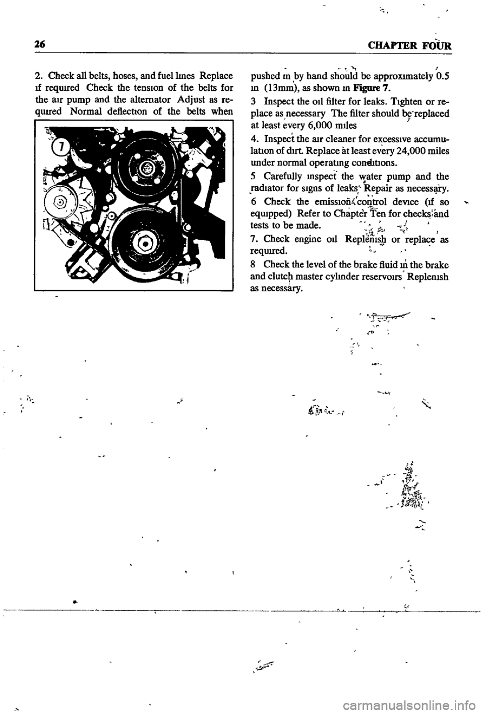
approXImately
0
5
m
13mm
as
shown
m
Figure
7
3
Inspect
the
011
filter
for
leaks
TIghten
or
re
place
as
necessary
The
filter
should
replaced
at
least
every
6
000
mIles
4
Inspect
the
lIlr
cleaner
for
excessIve
accumu
latIon
of
dIrt
Replace
at
least
every
24
000
miles
under
normal
operatmg
cornhtIons
5
Carefully
mspect
the
water
pump
and
the
radIator
for
SIgnS
of
leaks
Repair
as
necessl
i
y
6
Check
the
emissIoo
control
deVice
If
so
eqwpped
Refer
to
Chapter
Ten
for
checks
and
tests
to
be
made
c
1
7
Check
engine
oIl
Replems
9
or
replace
as
reqUIred
8
Check
the
level
of
the
brake
fluid
m
the
brake
and
clutcJ1
master
cylmder
reservOirs
ReplenISh
as
necessary
ii
t
d
fl
tlJ
l
Page 43 of 252

38
CHAPTER
SIX
EMISSION
CONTROL
DEVICES
All
Datsuns
have
a
sealed
type
of
crankcase
emISSion
control
device
and
an
exhaust
emISsion
control
deVice
Models
sold
m
Cahfornla
smce
1970
also
have
an
evaporative
emisSion
control
deVice
An
rmportant
part
of
the
exhaust
control
device
is
the
air
pump
located
at
the
bottom
left
hand
side
of
the
engme
It
IS
dnven
by
a
belt
off
of
the
crankshaft
pulley
and
supphes
air
to
the
exhaust
system
In
1972
an
electric
blower
in
corporated
m
the
air
cleaner
replaced
the
mechanical
pumI
ENGINE
REMOVAL
Expenence
has
shown
It
IS
easier
to
remove
the
engine
and
the
transmission
as
a
smgle
UnIt
than
to
remove
the
engme
alone
Once
the
en
gine
and
transmiSSIon
are
out
of
the
vehIcle
the
tranSmIssion
can
be
detached
from
the
engme
To
remove
the
engme
transmISsion
proceed
as
follows
1
Scribe
ahgnment
marks
on
the
hood
around
the
hmges
ThIS
will
make
remstallatlon
eaSIer
2
Remove
the
two
bolts
that
secure
each
hInge
and
remove
the
hood
It
is
not
necessary
to
re
move
the
hood
support
from
the
engme
firewall
3
DISconnect
the
lower
radIator
hose
from
the
right
hand
SIde
of
the
engine
and
at
the
bottom
of
the
radIator
ThIS
will
pernnt
coolant
to
dram
from
the
engme
and
the
radIator
4
Remove
the
draIn
plugs
from
the
engine
pan
and
translIDSsIon
and
completely
dram
lubn
cants
Into
suitable
contamers
5
DISconnect
the
battery
cables
from
the
bat
tery
loosen
the
two
hold
down
clamps
and
re
move
the
battery
NOTE
The
location
and
number
of
hoses
to
be
removed
from
the
air
cleaner
varies
from
model
to
model
It
IS
normally
easier
to
remove
the
hoses
from
the
sources
rather
than
try
to
dISconnect
them
from
yndemeath
the
air
cleaner
The
1972
model
Will
requlre
dlsconnectlOn
of
the
electrica1
cirCUit
In
the
air
cleaner
system
wing
nut
from
the
top
of
the
air
cleaner
and
remove
the
aIr
cleaner
7
DIsconnect
the
upper
radiator
hose
from
the
radiator
and
the
thermostat
housmg
Remove
the
hose
8
Disconnect
the
two
heater
hoses
from
the
nght
hand
side
of
the
engme
TIe
these
bac
so
they
won
t
interfere
with
removal
of
the
engme
9
Remove
the
radIator
grille
by
unscrewing
all
mountmg
screws
10
Remove
the
four
mounting
screws
holding
the
fan
shield
to
the
backside
of
the
radiator
11
Remove
the
four
mountmg
bolts
holdIng
the
radiator
In
place
In
automatic
tranSmISsion
models
dISconnect
the
two
transnnsslOn
oIl
cooler
lInes
from
the
bottom
of
the
radiator
Pull
the
radiator
straight
up
to
remove
Remove
the
fan
shield
12
Loosen
the
adjustment
and
mounting
bolts
from
the
retamIng
brackets
on
the
alternator
and
air
pump
If
so
eqwpped
The
alternator
is
lo
cated
at
the
bottom
nght
hand
Side
of
the
engme
and
the
air
pump
on
the
lower
left
hand
Side
13
Loosen
tenSIon
on
the
two
dnve
belts
re
move
the
belts
from
the
alternator
and
air
pump
and
then
from
the
fan
pulleys
14
Remove
the
bolts
holdIng
the
fan
and
pulley
to
the
water
pump
assembly
and
remove
the
fan
and
pulley
15
DISconnect
the
fuel
hne
from
the
fuel
pump
16
DIsco
ect
accelerator
control
linkage
and
choke
WIre
at
the
carburetor
17
Disconnect
the
wiring
from
the
starter
motor
alternator
Ignition
coIl
oIl
pressure
switch
and
temperature
transmItting
unit
NOTE
The
following
steps
are
per
formed
from
under
the
car
lack
up
the
front
of
the
car
and
position
stands
under
the
front
support
points
to
proVide
working
room
under
the
vehicle
WARNING
Never
climb
under
a
vehicle
that
is
supported
by
the
lack
only
If
stands
are
not
avflllable
sturdy
wooden
blocks
can
be
U3ed
6
Disconnect
all
hoses
that
lead
to
the
air
cleaner
remove
two
bolts
that
hold
the
air
cleaner
to
its
mountmg
bracket
unscrew
the
18
Remove
two
bolts
holdIng
the
clutch
operat
Ing
cylInder
to
the
flywheel
hOUSIng
shown
m
Page 64 of 252

ENGINE
59
2
Coat
the
pan
gasket
on
both
sides
With
gasket
compound
and
attach
the
oil
pan
to
the
cyhnder
block
Torque
as
specIfied
Manifold
and
Carburetor
Installation
1
Install
the
mtake
and
exhaust
manIfolds
WIth
associated
gasket
to
the
cylmder
head
2
Mount
the
carburetor
and
gasket
to
the
mtake
manIfold
2
Adjust
all
mtake
and
exhaust
valves
to
the
specIfied
clearance
for
a
cold
engme
Clutch
Assembly
Installation
CAUTION
Take
extreme
care
not
to
get
grease
or
011
on
the
clutch
or
flywheel
frlc
hon
contact
surfaces
1
Place
the
clutch
disc
assembly
on
the
flywheel
With
the
longer
chamfered
splmed
end
of
the
dISC
toward
the
transmISSion
2
Visually
align
or
use
a
dummy
splmed
dnve
shaft
to
ahgn
the
diSC
assembly
With
the
flywheel
pilot
beanng
3
Install
and
tighten
the
SIX
bolts
holdmg
the
clutch
cover
assembly
to
the
flywheel
Tighten
the
bolts
a
turn
each
tune
by
diagonal
pattern
until
they
are
tight
Tlghtenmg
torque
should
be
174
to
188ft
lbs
24
to
2
6
kg
m
NOTE
There
are
two
dowels
on
the
flywheel
to
locate
the
clutch
cover
4
Remove
dummy
shaft
If
used
after
the
above
bolts
are
fully
tightened
5
Refit
the
release
bearing
and
translI11Ssion
case
Miscellaneous
Installation
1
Connect
the
fuel
hose
on
the
front
part
of
the
engme
to
the
fuel
pump
and
to
the
carburetor
2
Gap
the
spark
plugs
and
mstall
them
usmg
new
gaskets
3
Coat
the
rocker
arm
cover
gasket
With
sealer
and
position
It
on
the
cylmder
head
4
Install
the
rocker
arm
cover
and
tighten
the
two
thumb
screws
that
hold
it
m
place
5
Install
distrIbutor
makmg
certam
that
the
notch
on
the
distributor
shaft
assembly
mates
With
the
drive
spmdle
Ahgn
the
location
marks
made
dunng
disassembly
so
that
the
distrIbutor
is
positioned
as
before
6
Install
and
tighten
the
bolts
which
hold
the
dIStributor
to
the
front
cover
7
Install
pomts
condenser
and
rotor
8
Replace
distrIbutor
cap
and
attach
spark
plug
Wires
m
the
correct
sequence
Make
certain
that
all
wires
are
firmly
seated
m
the
distrIbutor
cap
and
attached
securely
to
the
spark
plugs
9
HOISt
the
engme
assembly
from
the
work
stand
10
Install
the
alternator
bracket
alternator
and
engme
mounts
to
the
block
11
Install
the
IgnItIon
coil
oil
filter
oil
pressure
SWitch
dipstick
and
water
drain
plug
12
Connect
the
vacuum
Ime
between
the
dis
trIbutor
and
carburetor
13
Connect
the
transIDlSSlOn
to
the
engine
prior
to
mstallatIon
m
the
vehicle
Engine
Installation
Installation
is
the
reverse
of
the
procedures
followed
m
removal
Be
certaIn
thatlall
battery
connections
are
made
that
water
hoses
are
se
cured
wmng
IS
connected
properly
and
that
all
required
bolts
and
mounts
are
mstalled
and
tightened
Replace
the
radiator
fan
belts
and
radiator
shroud
Fill
the
engme
With
the
proper
grade
of
oil
and
the
radiator
With
recommended
coolant
Install
the
hood
to
the
hInges
according
to
the
marks
made
dUrIng
removal
SERVICE
DATA
AND
SPECIFICATIONS
Table
1
covers
servIce
data
and
engme
Speci
fications
Page 90 of 252

COOLING
SYSTEM
8S
and
In
those
with
exhaust
and
evaporatIve
emIS
sion
control
devIces
a
fan
clutch
IS
combIned
WIth
the
thermostat
to
detect
temperature
m
the
engme
compartlnent
When
the
temperature
nses
the
thermostat
detects
the
change
an
the
fan
clutch
engages
thereby
helpmg
to
cool
the
engme
WATER
PUMP
Figure
2
page
86
IS
an
exploded
drawmg
of
the
water
pump
and
fan
assembly
for
1970
to
1971
The
top
half
of
the
IllustratIon
applIes
to
those
models
WIth
exhaust
and
evaporatIve
emiSSIOn
control
systems
The
bottom
half
covers
models
WIth
a
crankcase
emiSSIon
control
deVIce
only
Figure
3
page
87
IS
an
exploded
drawmg
of
the
water
pump
and
fan
assembly
for
1968
models
Without
exhaust
or
evaporatIve
controls
Figure
4
page
88
shows
the
1968
model
With
emISSIon
control
deVIce
As
can
be
seen
from
the
illustratIons
most
dIfferences
eXISt
withIn
the
fan
clutch
assembly
Water
Pump
Removal
1
Remove
upper
and
lower
radIator
hoses
from
the
thermostat
housmg
and
cylmder
block
re
spectIvely
Dram
coolant
from
rad1ator
and
cylInder
block
2
Loosen
the
alternator
mountlng
bolt
and
the
adjustIng
bolt
on
the
alternator
mountIng
bracket
3
Move
the
alternator
toward
the
cylinder
block
untIl
slack
IS
eVIdent
10
the
fan
belt
Re
move
fa
belt
fro
alternator
water
pump
and
crankshaft
pulley
4
It
IS
difficult
to
remove
the
water
pump
from
the
front
housmg
With
the
radiator
and
top
shroud
10
place
so
remove
them
5
Remove
the
bolts
holdmg
the
fan
assembly
to
the
water
pump
and
remove
the
fan
assembly
6
Remove
the
bolts
holdmg
the
water
pump
to
the
front
housmg
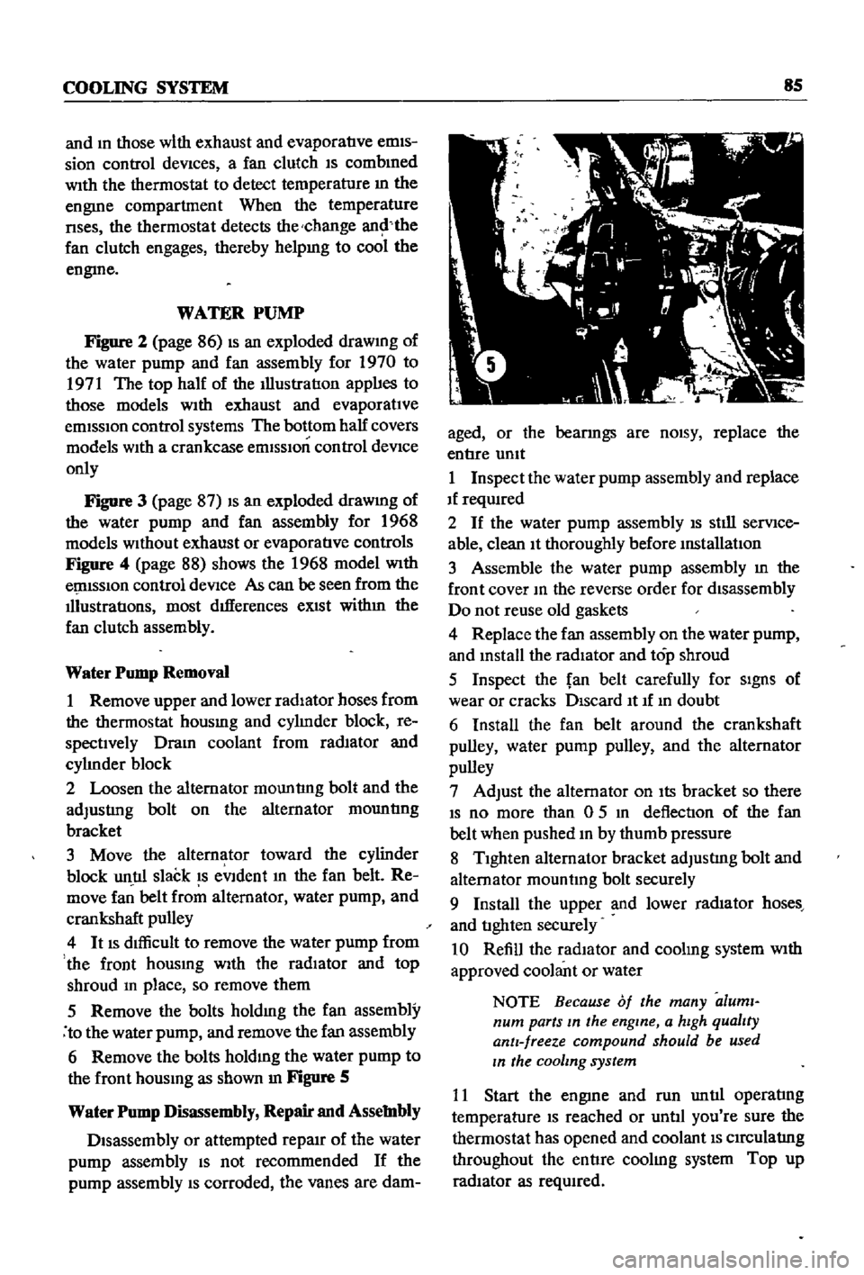
as
shown
In
Figure
S
Water
Pump
Disassembly
Repair
and
Assembly
Disassembly
or
attempted
repaIr
of
the
water
pump
assembly
IS
not
recommended
If
the
pump
assembly
IS
corroded
the
vanes
are
dam
aged
or
the
bearmgs
are
nOISY
replace
the
entIre
umt
1
Inspect
the
water
pump
assembly
and
replace
If
reqUIred
2
If
the
water
pump
assembly
IS
stIll
serVIce
able
clean
It
thoroughly
before
mstallatIon
3
Assemble
the
water
pump
assembly
m
the
front
cover
10
the
reverse
order
for
disassembly
Do
not
reuse
old
gaskets
4
Replace
the
fan
assembly
on
the
water
pump
and
mstall
the
radiator
and
top
shroud
5
Inspect
the
fan
belt
carefully
for
SIgnS
of
wear
or
cracks
DIscard
It
If
10
doubt
6
Install
the
fan
belt
around
the
crankshaft
pulley
water
pump
pulley
and
the
alternator
pulley
7
Adjust
the
alternator
on
Its
bracket
so
there
IS
no
more
than
0
5
10
deflection
of
the
fan
belt
when
pushed
10
by
thumb
pressure
8
TIghten
alternator
bracket
adjustIng
bolt
and
alternator
mountmg
bolt
securely
9
Install
the
upper
and
lower
rad1ator
hoses
and
tIghten
securely
10
Refill
the
radIator
and
coolmg
system
With
approved
coolant
or
water
NOTE
Because
of
the
many
aluml
num
parts
In
the
engine
a
hIgh
qualIty
antI
freeze
compound
should
be
used
In
the
cooling
system
11
Start
the
engme
and
run
untIl
operatIng
temperature
IS
reached
or
untIl
you
re
sure
the
thermostat
has
opened
and
coolant
IS
CIrCulatIng
throughout
the
entIre
coolIng
system
Top
up
radIator
as
reqUIred
Page 103 of 252

98
CHAPTER
NINE
CHARGING
CIRCUIT
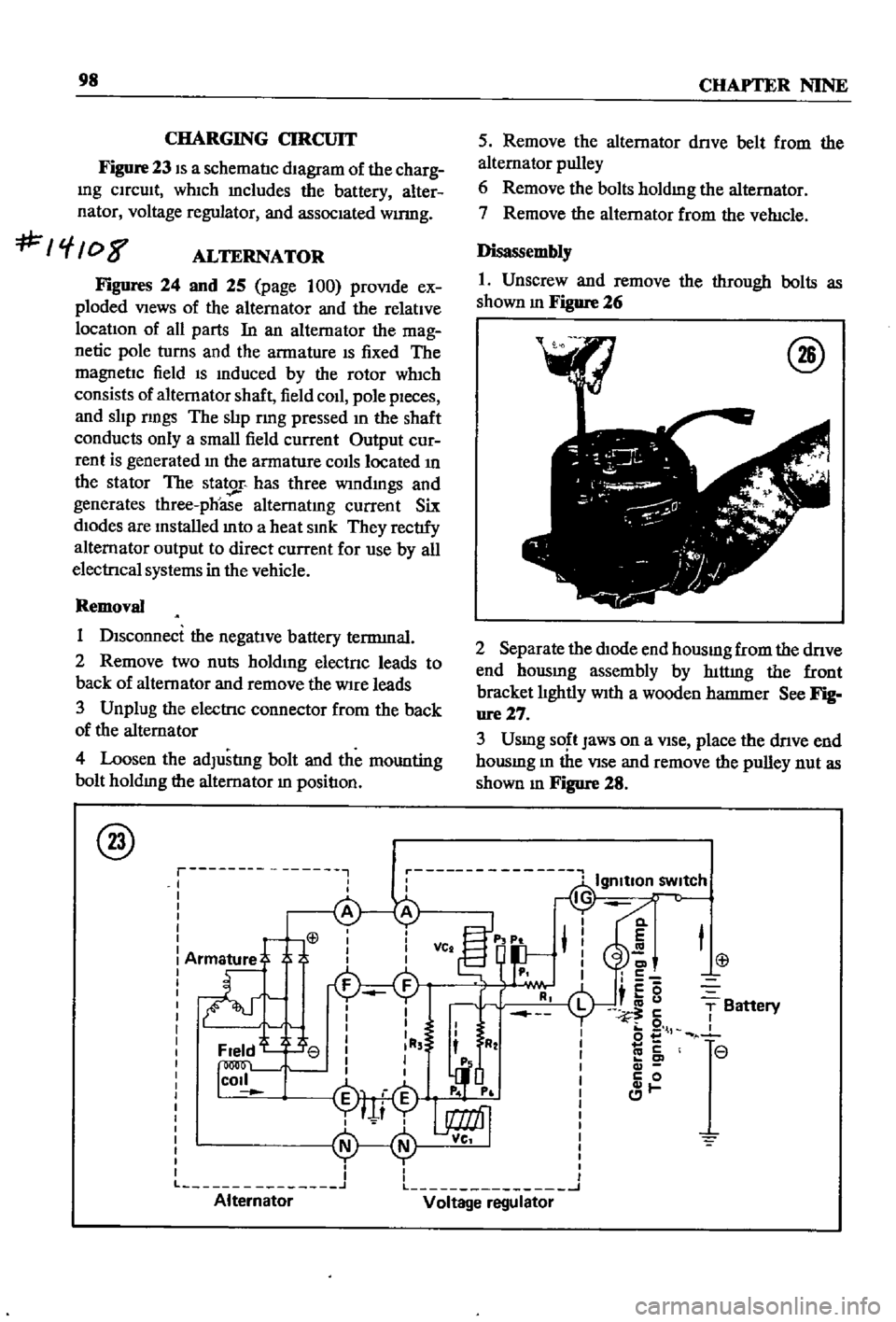
Figure
23
IS
a
schematIc
dIagram
of
the
charg
Ing
CIrcuIt
whIch
mcludes
the
battery
alter
nator
voltage
regulator
and
assocIated
wumg
f
08
ALTERNATOR
Figures
24
and
25
page
100
proVIde
ex
ploded
VIews
of
the
alternator
and
the
relatIve
locatIon
of
all
parts
In
an
alternator
the
mag
netic
pole
turns
and
the
armature
IS
fixed
The
magnetIc
field
IS
Induced
by
the
rotor
wh1ch
consists
of
alternator
shaft
field
coIl
pole
pIeces
and
slIp
nngs
The
slIp
rmg
pressed
In
the
shaft
conducts
only
a
small
field
current
Output
cur
rent
is
generated
In
the
armature
COIls
located
In
the
stator
The
stator
has
three
wIndmgs
and
generates
three
phoase
alternatIng
current
Six
dIodes
are
Installed
mto
a
heat
SInk
They
rectIfy
alternator
output
to
direct
current
for
use
by
all
electrIcal
systems
in
the
vehicle
Removal
1
DIsconnect
the
negatIve
battery
terrmnal
2
Remove
two
nuts
holdIng
electnc
leads
to
back
of
alternator
and
remove
the
Wire
leads
3
Unplug
the
electrIc
connector
from
the
back
of
the
alternator
4
Loosen
the
adJustlng
bolt
and
the
mounting
bolt
holdIng
the
alternator
In
positIon
@
r
I
I
I
L
Alternator
5
Remove
the
alternator
dnve
belt
from
the
alternator
pulley
6
Remove
the
bolts
holdmg
the
alternator
7
Remove
the
alternator
from
the
veh1cle
Disassembly
1
Unscrew
and
remove
the
through
bolts
as
shown
m
Figure
26
@
2
Separate
the
dIOde
end
housmg
from
the
dnve
end
hOUSIng
assembly
by
hlttmg
the
front
bracket
lIghtly
WIth
a
wooden
hatnnler
See
Fig
ure27
3
Usmg
SO
t
Jaws
on
a
VIse
place
the
dnve
end
housmg
m
the
VIse
and
remove
the
pulley
nut
as
shown
m
Figure
28
Cl
E
C
c5
i
u
5
o
l
co
c
c
0
1
T
Battery
r
r
L
J
Voltage
regulator