Page 9 of 252

4
CHAPTER
ONE
chassIs
number
Write
the
numbers
down
and
carry
them
ill
your
wallet
Service
Hints
Throughout
thIs
manual
keep
two
conven
bons
ill
mmd
Front
refers
to
the
front
of
the
vehicle
The
left
and
nght
sides
of
the
ve
hicle
refer
to
a
person
sittIng
ill
the
car
facing
forward
For
example
the
steenng
wheelIS
on
the
left
hand
Side
All
dimensIOns
and
capacities
are
expressed
ill
units
fanuhar
to
a
Umted
States
mechaniC
such
as
illches
and
pounds
Metric
measurements
are
also
given
Metnc
tools
are
reqUITed
to
work
on
the
Datsun
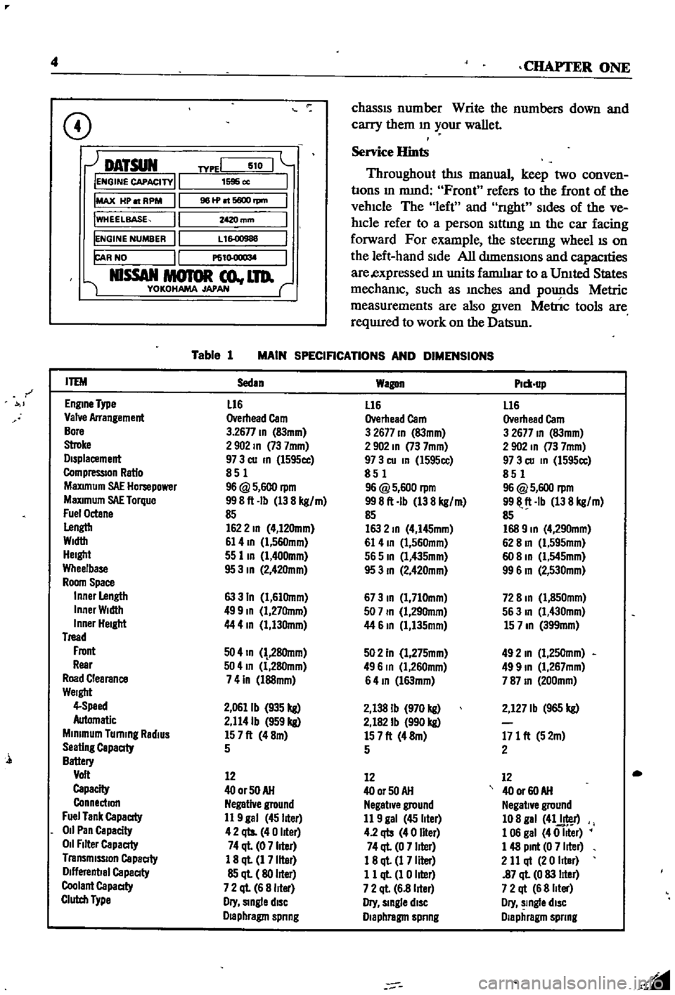
CD
DATSUN
IENGINE
CAPACITY
IMAX
HP
RPM
IWHEELBASE
IENGINE
NUMBER
FAR
NO
NlSSAN
MOTOR
co
LTD
YOKOHAMA
JAPAN
TYPEI
510
1595
cc
961P
6600
rpm
mm
L
1
00988
P61
l
O
1
l
M
Table
1
MAIN
SPECIFICATIONS
AND
DIMENSIONS
r
ITEM
Sedan
Wagon
Plm
up
EnglDe
Type
L16
L16
L16
Valve
Arrangement
Overhead
Cam
Overhead
Cam
Overhead
Cam
Bore
3
26n
ID
83mm
3
2677
ID
83mm
3
2677
ID
83mm
Stroke
2902
ID
73
7mm
2
902
ID
73
7mm
2
902
In
73
7mm
Displacement
97
3
cu
ID
l595cc
97
3
cu
In
l595cc
97
3
cu
ID
1595cc
CompressIOn
Ratio
851
851
851
MaXimum
SAE
Hompower
96
@
5
600
rpm
96
@
5
600
rpm
96
@
5
600
rpm
MaXimum
SAE
Torque
998ft
Ib
138
kg
m
998ft
Ib
138
kg
m
9911
ft
Ib
138
kg
m
Fuel
Octane
85
85
85
Lengtb
1622
ID
4
12Omm
163
2
ID
4
I45mm
168
9
ID
4
290mm
Width
61
4
ID
l
560mm
61
4
ID
1
560mm
62
8
In
Cl
595mm
Height
55
lID
1
400mm
565
ID
Cl
435mm
60
8
ID
Cl
545mm
Wheelbase
95
3
ID
2
42Omm
95
3
ID
2
420mm
99
6
In
2
530mm
Room
Space
Inner
Length
63
3
In
1
61Omm
673
ID
1
710mm
72
8
ID
1
850mm
Inner
Width
499
ID
1
27Omm
507
ID
1
29Omm
563
In
1
430mm
Inner
Height
44
4
In
1
130mm
44
61D
1
135mm
15
7
ID
399mm
Tread
Front
50
4
ID
28Omm
502
In
1
275mm
492
In
1
250mm
Rear
504
In
1
280mm
496
In
Cl
260mm
499
ID
1
267mm
Road
Clearance
741n
l88mm
64
ID
l63mm
787
ID
200mm
Weight
4
Speed
2
0611b
935
kg
2
138
Ib
970
kg
2
127
Ib
965
kg
Automatic
2
114Ib
959
kg
2
182
Ib
990
kg
Minimum
Turning
RadiUS
157ft
48m
157ft
48m
171
ft
52m
Seating
Capaaty
5
5
2
Battery
Volt
12
12
12
Capacity
400rSOAH
400r50AH
40
or
60
AH
Connection
Negative
ground
Negative
ground
Negative
ground
Fuel
Tank
Capaaty
11
9
gal
45
liter
11
9
gal
45
liter
108
gal
41J
r
011
Pan
Capacity
42
qts
40
liter
4
2
qb
40
liter
1
06
gal
40
Iller
011
Filter
Capaaty
74
ql
07
liter
74
ql
0
7
liter
1
48
Pint
0
7
liter
Transmission
Capaaty
1
8
ql
1
7
liter
18
ql
1
7
Iller
2
11
qt
20
Iller
Dlflerenbal
Capaaty
85
ql
80
liter
11
ql
1
0
liter
87
ql
0
83
lIter
Coolant
Capaaty
7
2
ql
6
8
liter
7
2
ql
6
8
lIter
7
2
qt
6
8
Iller
Clutch
Type
Dry
Single
diSC
Dry
slDgle
diSC
Dry
slDgle
diSC
Draphragm
spnng
Diaphragm
spnng
Diaphragm
spnng
l
Page 10 of 252

GENERAL
INFORMATION
5
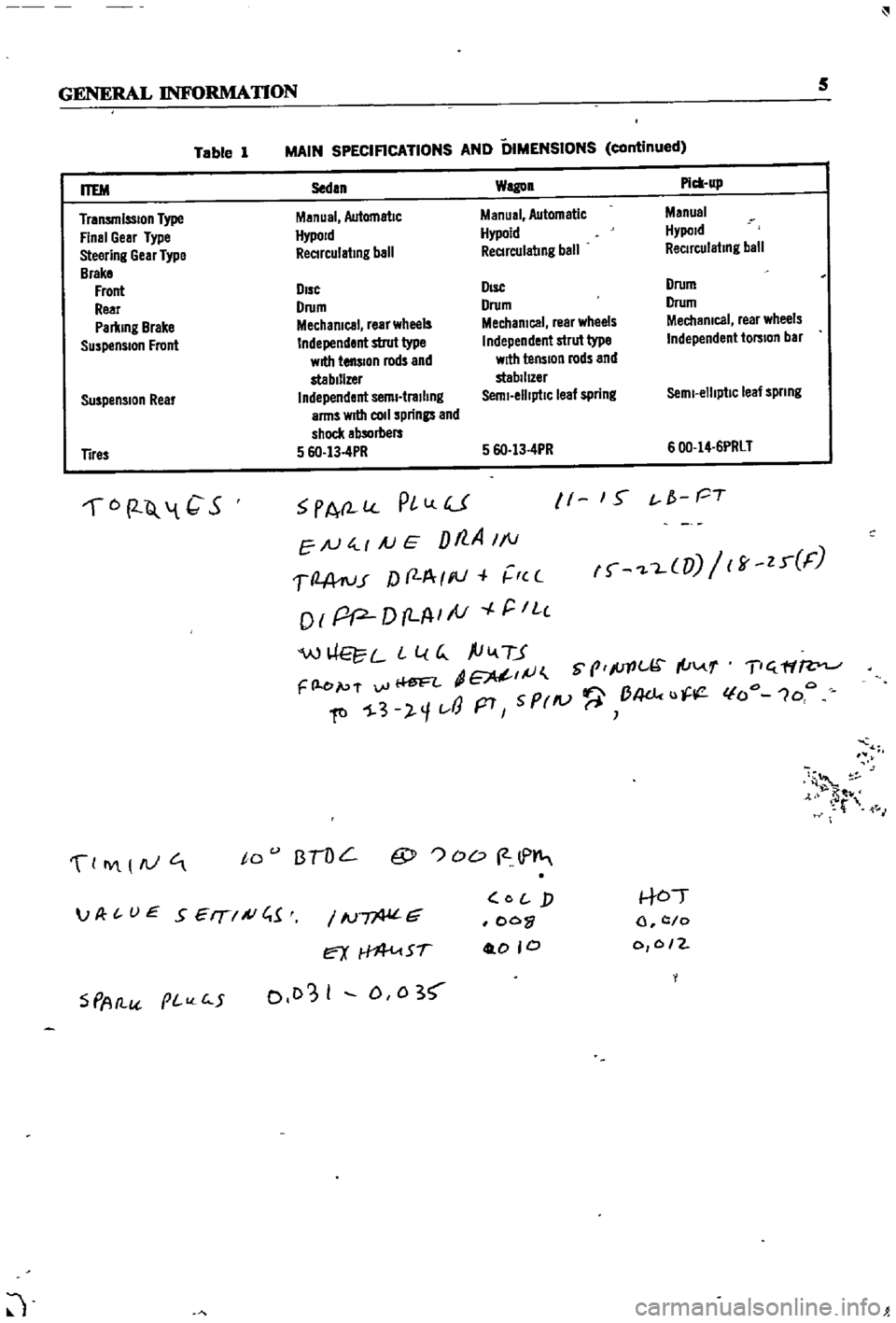
Table
1
MAIN
SPECIFICATIONS
AND
DIMENSIONS
continued
Suspension
Rear
Sedan
Wagon
Pick
up
Manual
Automatic
Manual
Automatic
Manual
HypoJd
Hypoid
Hypold
ReCIrculating
ball
ReCIrculating
ball
ReCirculating
ball
DIsc
DIsc
Drum
Drum
Drum
Drum
Mechanical
rear
wheels
Mechanical
rear
wheels
Mechanical
rear
wheels
Independent
strut
type
Independent
strut
type
Independent
torsion
bar
with
tension
rods
and
with
tension
rods
and
stabilizer
stabilIZer
Independent
semi
trailing
Semi
elliptiC
leaf
spring
Semi
elliptic
leaf
spnng
arms
wrtII
coli
springs
and
shock
absorbers
5
6O
13
4PR
5
6O
13
4PR
600
14
6PRLT
ITEM
Transmission
Type
Final
Gear
Type
Steering
Gear
Type
Brake
Front
Rear
Parking
Brake
Suspension
Front
Tires
6
2
Q
1
C
S
PA
l
PlLlU
EN
4
1
AJ
E
Dt7
A
1
1
1
2
A
ru
r
f
f
A
I
III
r
c
o
I
pP
D
LA
I
tV
r
IL
c
W
L
L
l
G
ftiv
TJ
dE
IJ
S
prlc
I
u
F
l
e
p
f
vi
Ii
ftl
1
3
l
1t
J
p7
5
PrlV
B4dc
u
11
1
S
t
f
PT
f
L
UJ
ff
zr
F
T
ff
lfo
1oo
4
t
M
0
IY
AJ
to
BTOL
@
OD
2
lP
S
PAtl
pI
c
5
IN
G
ex
Sf
0103
I
D
0
3
O
j
oo
0
0
0
to
l
c
o
0
0
2
JP
t
UE
SEIT
A
C
1
J
Page 11 of 252

CHAPTER
TWO
PERIODIC
MAINTENANCE
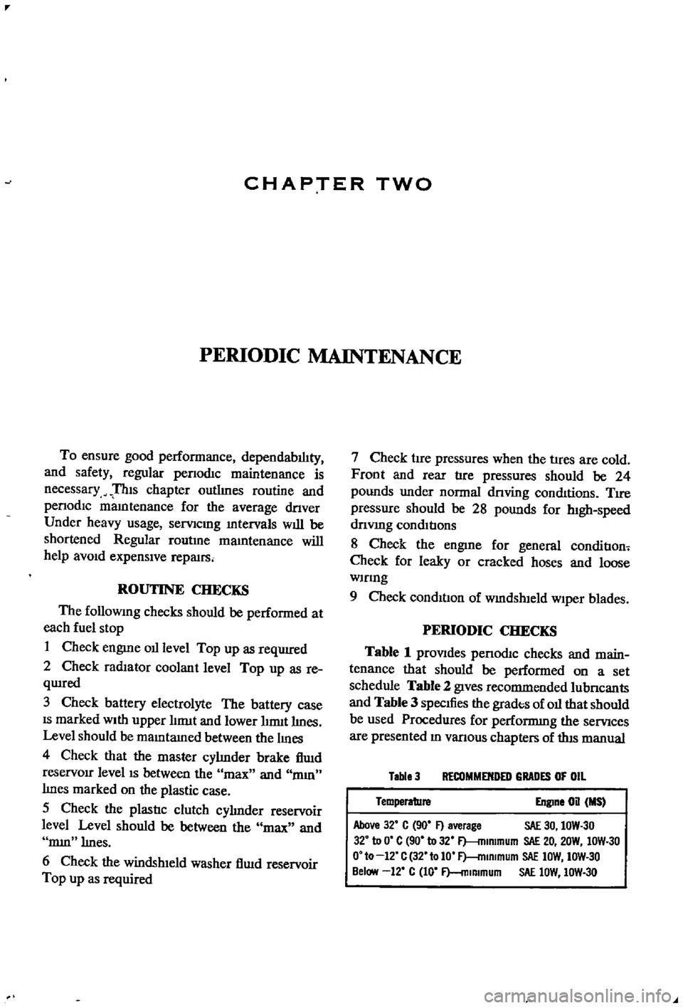
To
ensure
good
performance
dependability
and
safety
regular
penodlc
maintenance
is
necessary
TIns
chapter
outlInes
routine
and
penodlc
mamtenance
for
the
average
dnver
Under
heavy
usage
semcmg
mtervals
will
be
shortened
Regular
routme
mamtenance
will
help
aVOId
expensive
repaIrs
ROUTINE
CHECKS
The
followlDg
checks
should
be
performed
at
each
fuel
stop
1
Check
engme
oil
level
Top
up
as
requrred
2
Check
radiator
coolant
level
Top
up
as
re
qwred
3
Check
battery
electrolyte
The
battery
case
IS
marked
With
upper
hrmt
and
lower
lnmt
lInes
Level
should
be
maID
tamed
between
the
IIDes
4
Check
that
the
master
cylInder
brake
flwd
reservOir
level
IS
between
the
max
and
mm
lInes
marked
on
the
plastic
case
S
Check
the
plastic
clutch
cyhnder
reservoir
level
Level
should
be
between
the
max
and
mm
lInes
6
Check
the
windsh1eld
washer
flwd
reservoir
Top
up
as
required
7
Check
tire
pressures
when
the
tIres
are
cold
Front
and
rear
tire
pressures
should
be
24
pounds
under
normal
dnving
conditions
TIre
pressure
should
be
28
pounds
for
h1gh
speed
dnvmg
conditions
8
Check
the
engIne
for
general
conditIon
Check
for
leaky
or
cracked
hoses
and
loose
wmng
9
Check
condition
of
wmdshleld
wiper
blades
PERIODIC
CHECKS
Table
1
prOVIdes
penodIc
checks
and
main
tenance
that
should
be
performed
on
a
set
schedule
Table
2
gIves
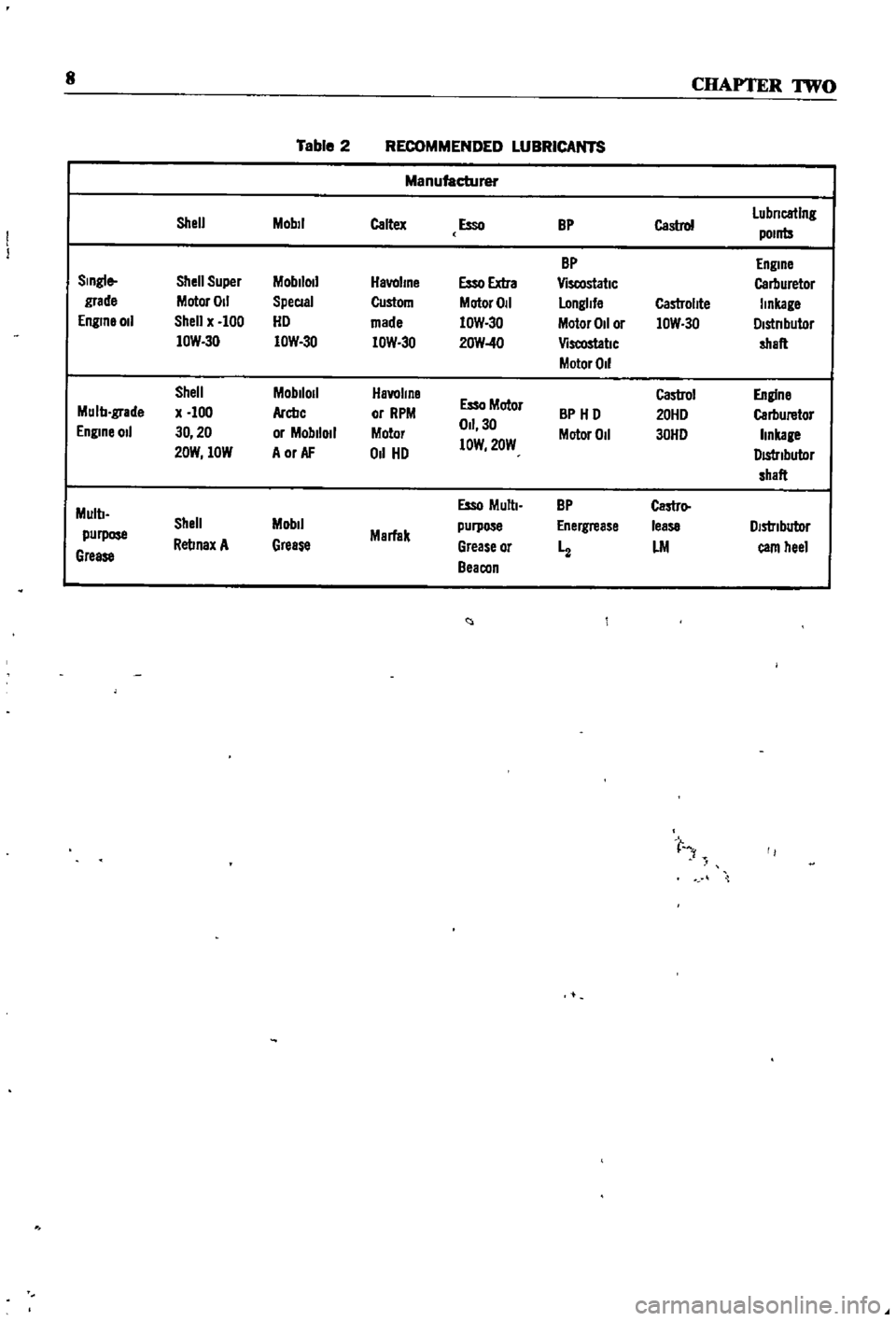
recommended
lubncants
and
Table
3
specIfies
the
grades
of
oil
that
should
be
used
Procedures
for
performmg
the
semces
are
presented
ID
vanous
chapters
of
tlus
manual
Table
3
RECOMMENDED
GRADES
OF
OIL
Temperature
Engine
on
MS
Above
32
C
90
F
average
SAE
30
IOW
30
32
to
0
C
90
to
32
F
mlmmum
SAE
20
20W
IOW
30
O
to
12
C
32
tolO
F
mlRlmum
SAE
IOW
IOW
30
Below
12
C
10
F
mlmmum
SAE
lOW
IOW
30
Page 12 of 252

PERIODIC
MAINTENANCE
7
Table
1
ENGINE
LUBRICATION
AND
MAINTENANCE
FREQUENCY
EVERY
E
E
E
E
E
E
E
Eo
00
00
00
00
00
00
00
gq
00
00
00
NO
t
r61li
0
CD
Check
engine
011
level
top
up
If
required
X
Change
engine
011
X
Lubricate
carburetor
hnkage
X
Lubricate
distributor
rotor
shaft
and
ann
shaft
X
Apply
grease
to
distributor
cam
heel
X
Check
radiator
coolant
level
X
Change
radIator
coolant
X
Change
radiator
coolant
additive
X
Check
battery
electrolyte
level
X
Check
specific
gravity
of
battery
X
Check
engine
starting
exhaust
color
X
Tighten
cyhnder
head
manifolds
and
pipe
flanges
X
Adjust
valve
clearance
X
Check
Ignition
timing
X
Tighten
carburetor
fittings
X
Check
fan
belt
tension
X
Check
for
011
pan
leakage
X
Tighten
engine
mounts
X
Check
fuel
strainer
X
Replace
fuel
strainer
X
Check
for
fuel
leaks
X
Replace
011
filter
X
Check
spark
plugs
X
Replace
spark
plugs
X
Check
dlstnbutor
cap
rotor
and
POints
X
Adjust
engine
Idle
speed
X
Check
air
cleaner
fittings
X
Clean
011
filler
cap
X
Clean
battery
cables
and
terminals
X
Check
alternator
and
voltage
regulator
function
X
Check
starter
motor
function
X
Replace
aIr
cleaner
element
X
Check
fuel
pump
function
X
Check
cyhnder
compressIon
X
Clean
carburetor
Jets
and
float
chamber
X
Check
dlstnbutor
condenser
X
Check
crankcase
ventilation
control
valve
X
Page 13 of 252
8
CHAPTER
TWO
Table
2
RECOMMENDED
LUBRICANTS
Manufacturer
Shell
Mobil
Caltex
Esso
BP
Castro
Lubncatlng
pomts
BP
ngme
Single
Shell
Super
Moblloll
Havahne
Esso
Extra
ViscostatlC
Carburetor
grade
Motor
011
SpeCial
Custom
Motor
011
longUe
Castrollte
linkage
ngme
011
Shell
x
100
HD
made
IOW
30
Motor
011
or
IOW
30
Dlstnbutor
lOW
3D
IOW
30
lOW
3D
20W
40
ViscostatlC
shaft
Motor
011
Shell
Moblloll
Havallne
Castrol
Engine
Mulb
grade
x
100
Arcbc
or
RPM
Esso
Motor
BP
HD
20HD
Carburetor
ngme
011
30
20
or
Moblloll
Motor
011
30
Motor
011
30HD
hnkage
20W
lOW
A
or
AF
011
HD
lOW
20W
DIStributor
shaft
Mulb
Esso
Multl
BP
Castro
Shell
Mobil
purpose
nergrease
lease
DIstnbutor
purpose
Rellnax
A
Grease
Marfak
Grease
or
LM
eam
heel
Grease
Beacon
t
r
Page 14 of 252

CHAPTER
THREE
TROUBLESHOOTING
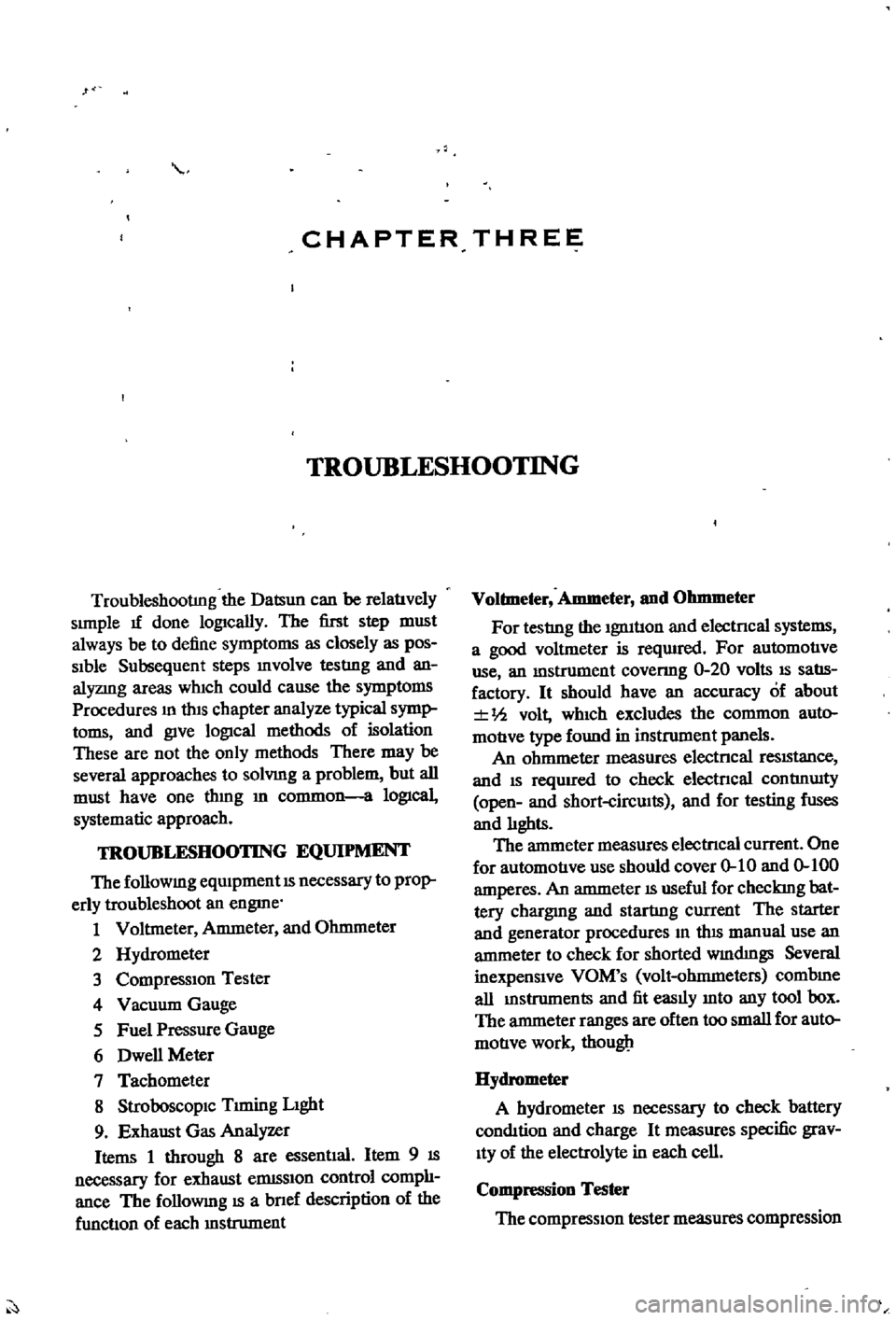
TroubleshootIng
the
Datsun
can
be
relatlvely
simple
1f
done
lOgically
The
first
step
must
always
be
to
define
symptoms
as
closely
as
pos
Sible
Subsequent
steps
mvolve
testIng
and
an
alyzmg
areas
which
could
cause
the
symptoms
Procedures
m
thiS
chapter
analyze
typical
symp
toms
and
give
lOgical
methods
of
isolation
These
are
not
the
only
methods
There
may
be
several
approaches
to
solvmg
a
problem
but
all
must
have
one
thmg
m
common
a
lOgical
systematic
approach
TROUBLESHOOTING
EQUIPMENT
The
followmg
eqUipment
is
necessary
to
prop
erly
troubleshoot
an
engme
1
Voltmeter
Ammeter
and
Ohmmeter
2
Hydrometer
3
Compression
Tester
4
Vacuum
Gauge
5
Fuel
Pressure
Gauge
6
Dwell
Meter
7
Tachometer
8
StroboscopiC
Trming
Light
9
Exhaust
Gas
Analyzer
Items
1
through
8
are
essentlal
Item
9
is
necessary
for
exhaust
elDlSSion
control
comph
ance
The
followmg
is
a
bnef
description
of
the
functlon
of
each
mstrument
Voltmeter
Ammeter
and
Ohmmeter
For
testIng
the
ignitlon
and
electncal
systems
a
good
voltmeter
is
reqUIred
For
automotIve
use
an
mstrument
covenng
0
20
volts
is
salls
factory
It
should
have
an
accuracy
of
about
Ih
volt
which
excludes
the
common
auto
moUve
type
found
in
instrument
panels
An
ohmmeter
measures
electncal
reSiStance
and
is
reqUired
to
check
electncal
contInUity
open
and
short
circwts
and
for
testing
fuses
and
hghts
The
ammeter
measures
electncal
current
One
for
automotIve
use
should
cover
0
10
and
0
100
amperes
An
ammeter
is
useful
for
checkmg
bat
tery
chargmg
and
startIng
current
The
starter
and
generator
procedures
m
tlus
manual
use
an
ammeter
to
check
for
shorted
wmdmgs
Several
inexpensive
VOM
s
volt
ohmmeters
combme
all
mstruments
and
fit
easily
mto
any
tool
box
The
ammeter
ranges
are
often
too
small
for
auto
motIve
work
thougll
Hydrometer
A
hydrometer
is
necessary
to
check
battery
condition
and
charge
It
measures
specific
grav
ity
of
the
electrolyte
in
each
cell
Compression
Tester
The
compressiOn
tester
measures
compression
Page 15 of 252

10
CHAPTER
THREE
pressure
bUllt
up
In
each
cylInder
The
readIngs
when
properly
Interpreted
IndIcate
general
cyl
Inder
and
valve
condltlOn
Vacuum
Gauge
The
vacuum
gauge
IS
easy
to
use
but
dIfficult
for
an
Inexpenenced
mechanIC
to
Interpret
The
results
when
conSIdered
WIth
other
findIngs
can
prOVIde
valuable
clues
to
pOSSIble
trouble
Connect
the
vacuum
gauge
WIth
a
T
connec
tIon
In
the
hose
from
the
carburetor
to
the
vacuum
advance
on
the
dIstnbutor
Start
the
engme
and
let
It
warm
up
thoroughly
Vacuum
readIng
should
be
steady
at
18
22
Inches
NOTE
Subtract
1
Inch
from
reading
for
every
1000
feet
of
altitude
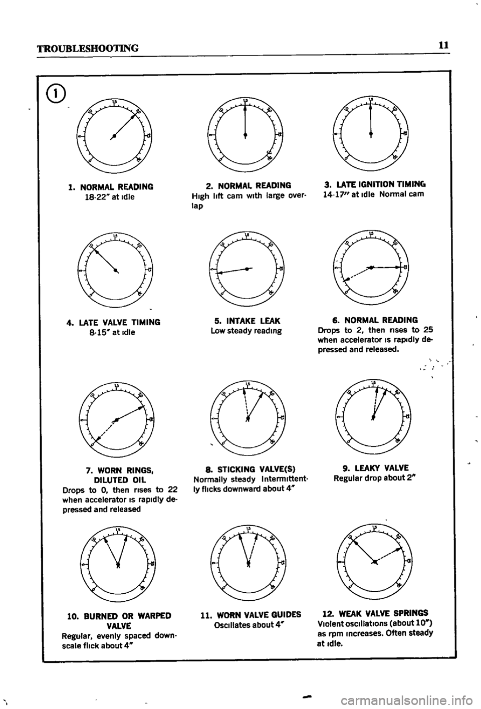
Figure
1
shows
numerous
tYPical
readIngs
WIth
InterpretatIons
Results
are
not
conclusive
WIthout
companng
to
other
tests
such
as
com
preSSIOn
readIngs
Fuel
Pressure
Gauge
ThIS
Instrument
IS
VItal
for
evaluatIng
fuel
pump
performance
Often
a
vacuum
gauge
and
fuel
pressure
gauge
are
combIned
Dwell
Meter
A
dwell
meter
measures
the
dIstance
In
de
grees
of
cam
rotatIon
that
the
breaker
pOInts
remaIn
closed
while
the
engme
IS
runnIng
SInce
thIS
angle
IS
determmed
by
breaker
pOInt
gap
the
dwell
angle
IS
an
accurate
IndIcatIon
of
pOInt
gap
Many
tachometers
Intended
for
tunIng
and
testIng
Incorporate
a
dwell
meter
as
well
Follow
the
manufacturer
s
InstructIon
to
measure
dwell
on
the
Datsun
Tachometer
A
tachometer
IS
essential
for
tunIng
Datsuns
WIth
exhaust
emission
control
deVices
IgmtIOn
turung
and
carburetor
adjustments
must
be
per
formed
at
the
specified
Idle
speed
The
best
In
strument
for
thIS
purpose
IS
one
WIth
a
range
of
0
1
000
or
0
2
000
rpm
Extended
range
0
6
000
or
8
000
Instruments
lack
accuracy
at
lower
speeds
The
InStrument
should
be
capable
of
detecting
changes
of
25
rpm
Stroboscopic
Timing
Light
ThIS
Instrument
pernuts
accurate
IgnitIon
tImIng
By
f1ashmg
a
bght
at
the
preCISe
Instant
cylInder
No
1
fires
the
posItIon
of
the
crank
shaft
pulley
at
that
Instant
can
be
seen
Marks
on
the
pulley
bne
up
With
a
reference
pOInter
on
the
block
dunng
the
tIming
procedure
SUltable
bghts
are
neon
bulb
types
and
xenon
strobe
hghts
Neon
tunmg
bghts
are
ddticult
to
see
and
must
be
used
in
dImly
bt
areas
Xenon
strobe
bghts
can
be
used
In
bnght
sunbght
Use
the
bght
accordIng
to
the
manufacturer
s
InStruC
tIons
Exhaust
Analyzer
Of
all
Instruments
descnbed
here
this
IS
the
least
bkely
to
be
owned
by
a
home
mechanic
One
Instrument
samples
the
exhaust
gases
from
the
taIlpIpe
and
measures
the
thermal
conduc
tIVIty
of
the
exhaust
gas
SInce
different
gases
conduct
heat
at
varYIng
rates
thermal
conduc
tIVIty
of
the
exhaust
IS
a
good
IndIcatIon
of
gases
present
This
Instrument
IS
VItal
for
accurately
checkIng
the
effectIveness
of
exhaust
emIssion
control
adjustments
but
IS
too
expenSIve
for
an
amateur
mechanIC
to
conSIder
buying
STARTER
Starter
system
troubles
are
relatIvely
easy
to
ISolate
The
followmg
are
common
symptoms
and
cures
1
Engme
cranks
very
slowly
or
not
at
all
Turn
on
the
headhghts
If
the
bghts
are
very
dun
most
likely
the
battery
or
the
connecting
WireS
are
at
fault
Check
the
battery
using
the
pro
cedures
descnbed
in
the
Tune
up
chapter
Check
wmmgfur
e
s
wom
andd
connectIom
H
the
battery
and
connectIng
WIres
check
good
turn
the
headlIghts
on
and
try
to
crank
the
engIne
H
the
lIghts
dIDl
drastIcally
the
starter
is
probably
shorted
to
ground
Remove
the
starter
and
test
it
usmg
the
procedures
gIven
in
Chapter
NIne
If
the
lights
remain
bnght
or
dun
slIghtly
when
crankIng
the
engme
the
trouble
may
be
in
the
starter
solenOId
or
wmng
To
ISolate
the
trouble
short
the
two
large
solenoid
ternunals
together
not
to
ground
if
the
starter
cranks
normally
check
the
solenoid
and
wmng
up
to
the
Page 16 of 252
TROUBLESHOOTING
11
CD
1
NORMAL
READING
18
22
at
Idle
4
LATE
VALVE
TIMING
8
15
at
Idle
7
WORN
RINGS
DILUTED
OIL
Drops
to
0
then
rises
to
22
when
accelerator
IS
rapidly
de
pressed
and
released
10
BURNm
OR
WARPED
VALVE
Regular
evenly
spaced
down
scale
flick
about
4
2
NORMAL
READING
High
11ft
cam
With
large
over
lap
5
INTAKE
LEAK
Low
steady
reading
8
STICKING
VALVE
S
Normally
steady
IntermIttent
1y
flicks
downward
about
4
11
WORN
VALVE
GUIDES
OsCillates
about
4
3
LATE
IGNITION
TIMINe
14
17
at
Idle
Normal
cam
6
NORMAL
READING
Drops
to
2
then
nses
to
25
when
accelerator
IS
raptdly
de
pressed
and
released
9
LEAKY
VALVE
Regular
drop
about
2
12
WEAK
VALVE
SPRINGS
Violent
OSCillations
about
1O
as
rpm
Increases
Often
steady
at
Idle