Page 169 of 252
164
CHAPTER
TWELVE
Rear
Axle
Removal
Pick
up
1
Jack
up
the
vehicle
and
support
It
With
stands
2
Remove
wheels
and
brake
drum
3
Remove
brake
shoe
and
chsconnect
hand
brake
WIre
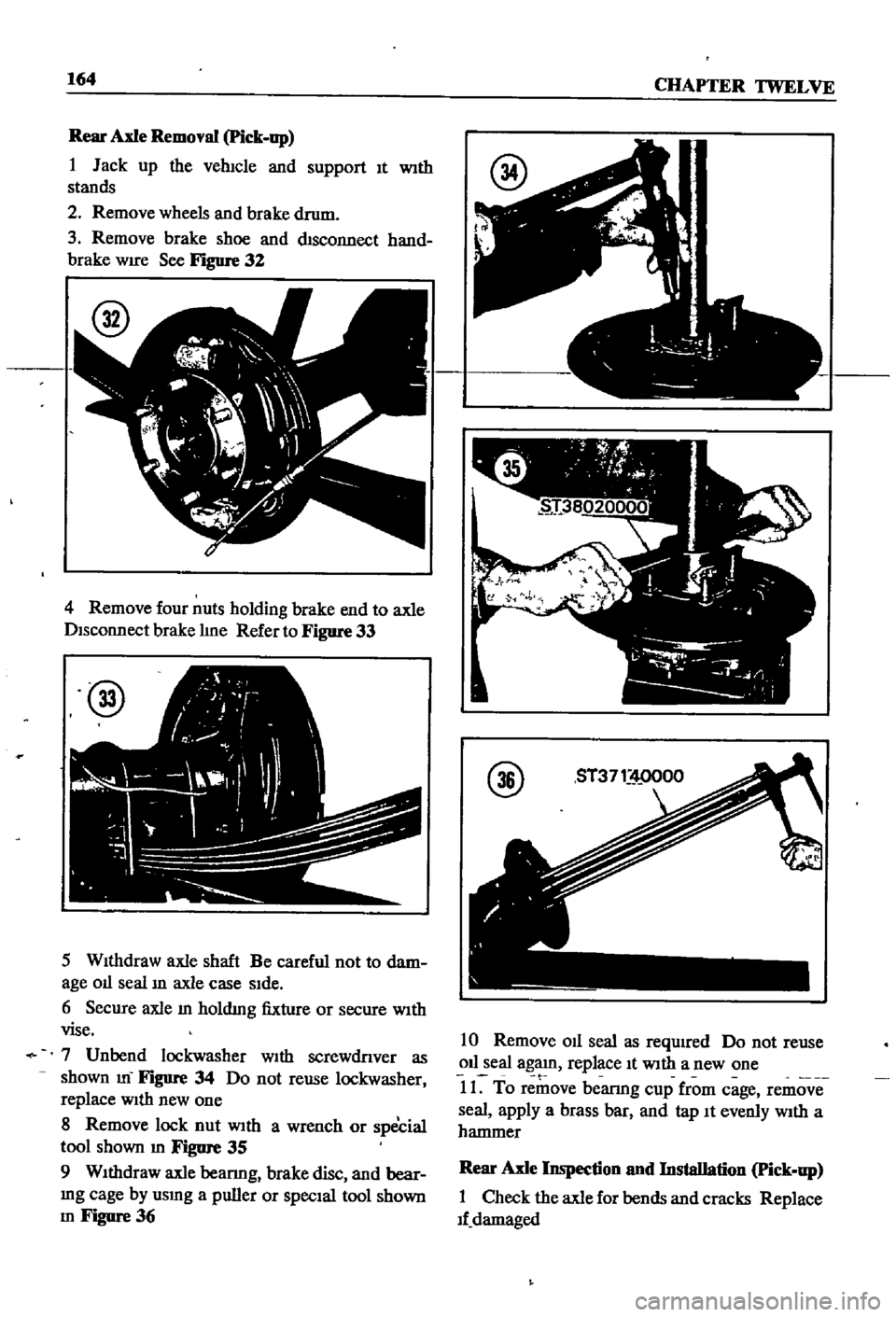
See
Figure
32
4
Remove
four
nuts
holding
brake
end
to
axle
Disconnect
brake
hne
Refer
to
Figure
33
@
5
WIthdraw
axle
shaft
Be
careful
not
to
dam
age
01l
seal
ill
axle
case
SIde
6
Secure
axle
m
holdmg
fixture
or
secure
WIth
vise
7
Unbend
lockwasher
With
screwdnver
as
shown
m
FIgure
34
Do
not
reuse
lockwasher
replace
With
new
one
8
Remove
lock
nut
With
a
wrench
or
special
tool
shown
m
Figure
35
9
WIthdraw
axle
beanng
brake
disc
and
bear
mg
cage
by
usmg
a
puller
or
SpecIal
tool
shown
m
Figure
36
@
10
Remove
011
seal
as
required
Do
not
reuse
011
seal
agaJn
replace
It
With
a
new
one
t
11
To
remove
bearmg
cup
from
cage
remove
seal
apply
a
brass
bar
and
tap
It
evenly
With
a
hammer
Rear
Axle
Inspection
nnd
Installation
Pick
up
1
Check
the
axle
for
bends
and
cracks
Replace
1f
damaged
Page 170 of 252

DIFFERENTIAL
REAR
AXLE
AND
REAR
SUSPENSION
165
2
Check
wheel
bearmgs
for
damage
or
noise
Replace
them
If
defective
3
Be
sure
to
use
new
011
seals
and
lockwashers
4
FIt
beanng
cup
and
grease
seal
to
cage
Tap
WIth
a
brass
hammer
while
fittIng
FIll
grease
seal
IIp
With
wheel
beanng
grease
after
fittmg
5
Install
brake
diSC
and
beanng
cage
on
axle
Fit
bearmg
cone
With
brass
bar
6
Tighten
lock
nut
Place
faced
Side
of
nut
to
washer
SIde
so
that
washer
IS
not
damaged
Torque
lock
nut
to
10S
to
145
ft
lb
15
to
20
kg
m
7
Match
washer
IIp
With
groove
m
nut
tIghten
nut
and
bend
washer
carefully
to
prevent
hp
damage
S
Use
a
brass
bar
to
fit
011
seal
to
tube
end
When
fitted
apply
grease
to
the
hp
Be
careful
not
to
deform
seal
or
damage
hp
9
Completely
fill
bearmg
With
grease
10
Install
shaft
AdJust
aXial
clearance
With
shIms
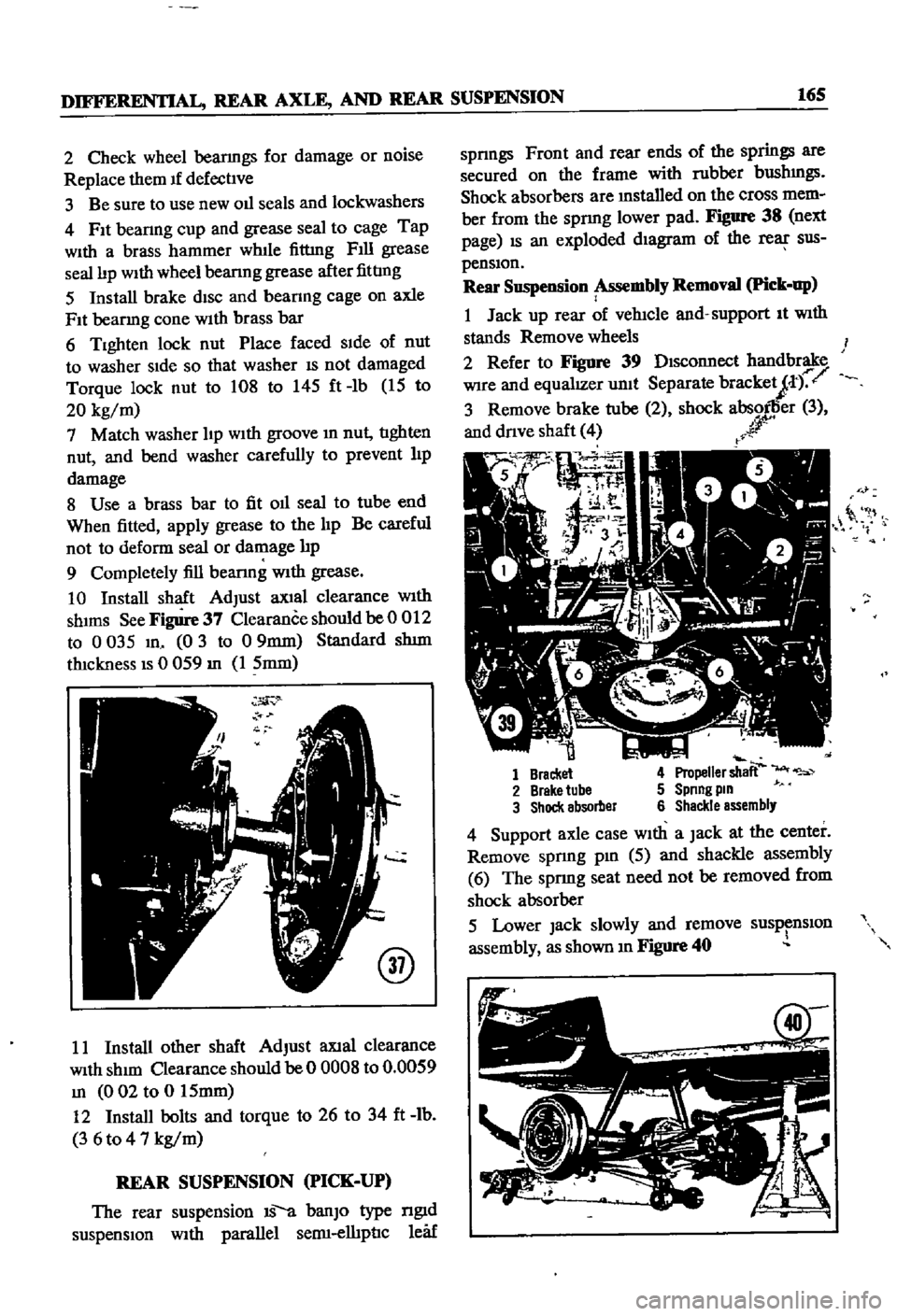
See
Figure
37
Clearance
should
be
0
012
to
0
035
m
0
3
to
09mm
Standard
shIm
thickness
IS
0
059
m
1
5mm
@
11
Install
other
shaft
AdJust
aXlal
clearance
With
shIm
Clearance
should
be
0
OOOS
to
0
0059
m
002
to
0
15mm
12
Install
bolts
and
torque
to
26
to
34
ft
lb
3
6
to
4
7
kg
m
REAR
SUSPENSION
PICK
UP
The
rear
suspension
IS
a
banJO
type
ngId
suspensIOn
With
parallel
semI
elhpnc
leaf
spnngs
Front
and
rear
ends
of
the
springs
are
secured
on
the
frame
with
rubber
bushmgs
Shock
absorbers
are
mstalled
on
the
cross
mem
ber
from
the
spnng
lower
pad
Figure
38
next
page
IS
an
exploded
dIagram
of
the
rear
sus
pensIOn
Rear
Suspension
Assembly
Removal
Pick
up
1
Jack
up
rear
of
vehicle
and
support
It
With
stands
Remove
wheels
2
Refer
to
Figure
39
DIsconnect
handbrake
Wire
and
equalIZer
unit
Separate
bracketJt
r
3
Remove
brake
tube
2
shock
absorller
3
and
dnve
shaft
4
r
r
0
it
1
Bracket
4
Propeller
shaft
2
Brake
tube
5
Spnng
pm
3
Shock
absorber
6
Shackle
assembly
4
Support
axle
case
With
a
Jack
at
the
center
Remove
spnng
pm
5
aJId
shackle
assembly
6
The
sprmg
seat
need
not
be
removed
from
shock
absorber
5
Lower
Jack
slowly
and
remove
susp
nslOn
assembly
as
shown
m
Figure
40
Page 171 of 252
166
CHAPTER
TWELVE
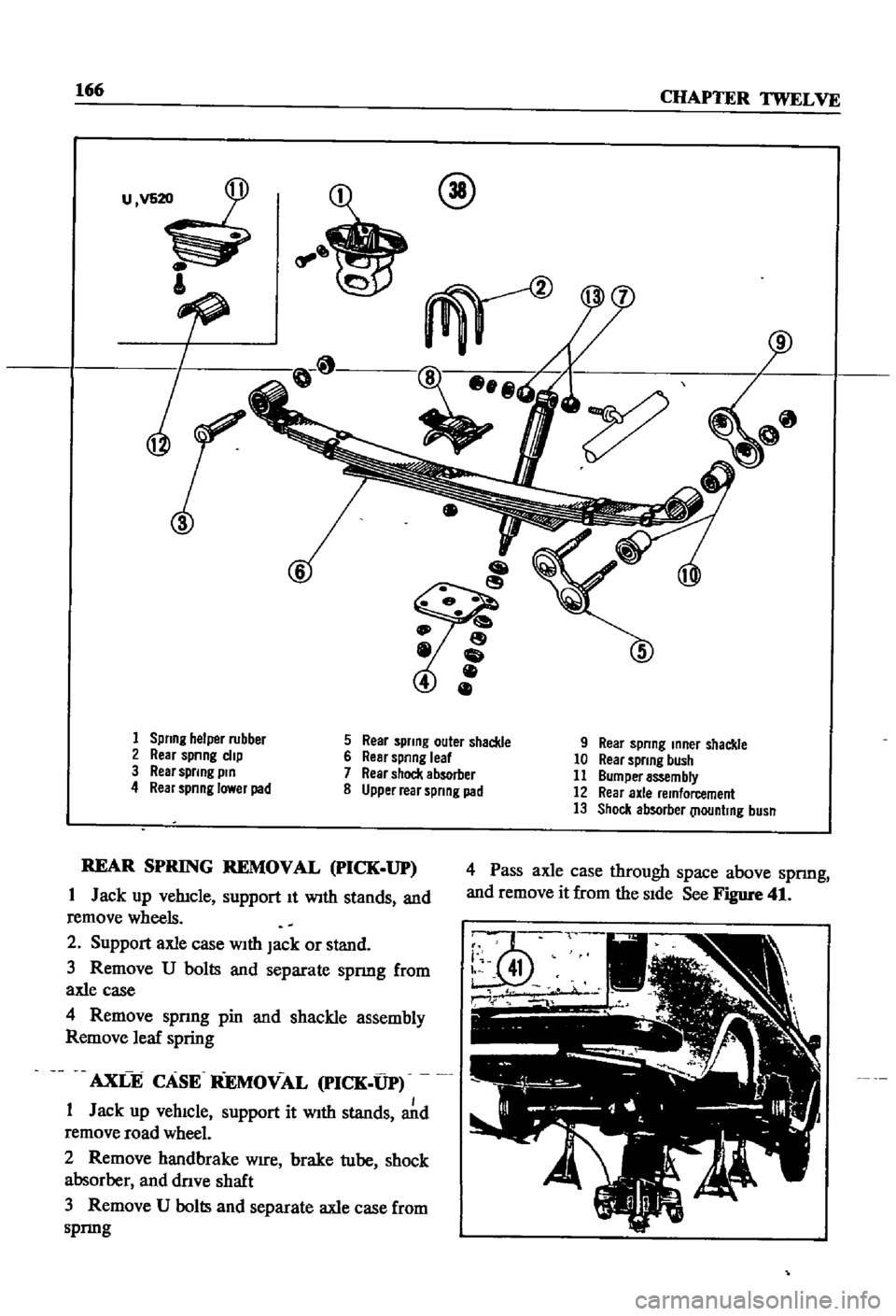
u
@
1
Spring
helper
rubber
5
Rear
spring
outer
shackle
9
Rear
spring
mner
shackle
2
Rear
spnng
clip
6
Rear
spring
leaf
10
Rear
spring
bush
3
Rear
sprmg
pm
7
Rear
shock
absorber
11
Bumper
assembly
4
Rear
spnnglawerpad
8
Upper
rear
spring
pad
12
Rear
axle
remforcement
13
Shock
absorber
llountmg
busn
REAR
SPRING
REMOVAL
pICK
UP
1
Jack
up
vehicle
support
It
With
stands
and
remove
wheels
2
Support
axle
case
With
Jack
or
stand
3
Remove
U
bolts
and
separate
spnng
from
axle
case
4
Remove
spnng
pin
and
shackle
assembly
Remove
leaf
spring
AXLE
CASE
REMOVAL
PICK
UP
1
Jack
up
vehIcle
support
it
With
stands
Jd
remove
road
wheel
2
Remove
handbrake
Wire
brake
tube
shock
absorber
and
dnve
shaft
3
Remove
U
bolts
and
separate
axle
case
from
spnng
4
Pass
axle
case
through
space
above
spnng
and
remove
it
from
the
SIde
See
Figure
41
Page 172 of 252

DIFFERENTIAL
REAR
AXLE
AND
REAR
SUSPENSION
167
REAR
SUSPENSION
pICK
UP
Rear
Suspension
Inspection
nnd
Repair
Pick
up
1
Check
spnngs
for
cracks
breaks
and
general
conditIon
Replace
as
reqwred
If
a
spnng
on
one
Side
IS
replaced
also
replace
the
other
one
2
Check
U
bolts
for
bends
stripped
threads
and
general
conditIon
Replace
as
reqUIred
3
Check
rubber
bumpers
and
bushings
for
cracks
wear
and
general
condll1on
Replace
if
defecl1ve
4
Check
shock
absorbers
for
leaks
or
other
damage
Replace
as
required
Rear
Suspension
Installation
Pick
up
1
Replace
the
rear
suspension
components
m
the
reverse
order
of
removal
2
When
msta11mg
rubber
bushmgs
coat
them
hghtly
With
a
soap
solution
3
Torque
parts
as
follows
Shackle
Pin
Spnng
Pm
U
Bolt
Secunng
Nut
Shock
Absorber
Upper
Nut
Shock
Absorber
Lower
Nut
Dnve
Shalt
Secunng
Bolt
83
to
94
It
Ib
11
5
to
13
kg
m
83
to
94
It
Ib
115
to
13
kg
m
61
to
72
ItAb
85
to
10
kg
m
26
to
31
It
Ib
36
t04
3
kg
m
10
to
12
ft
Ib
1
4
to
1
6
kg
m
18
to
22
ft
Ib
25
to
30
kg
m
NOTE
Retighten
bolts
and
nuts
that
hold
bushmgs
after
vehicle
has
been
removed
from
Jack
and
stands
Page 173 of 252

CHAPTER
THIRTEEN
FRONT
AXLE
FRONT
SUSPENSION
AND
STEERING
A
strut
type
front
suspension
IS
used
on
sedans
and
wagons
The
shock
absorber
and
the
spmdle
are
a
smgle
urnt
which
is
supported
by
a
coIl
spnng
on
the
upper
end
and
by
the
trans
verse
lInk
on
the
lower
end
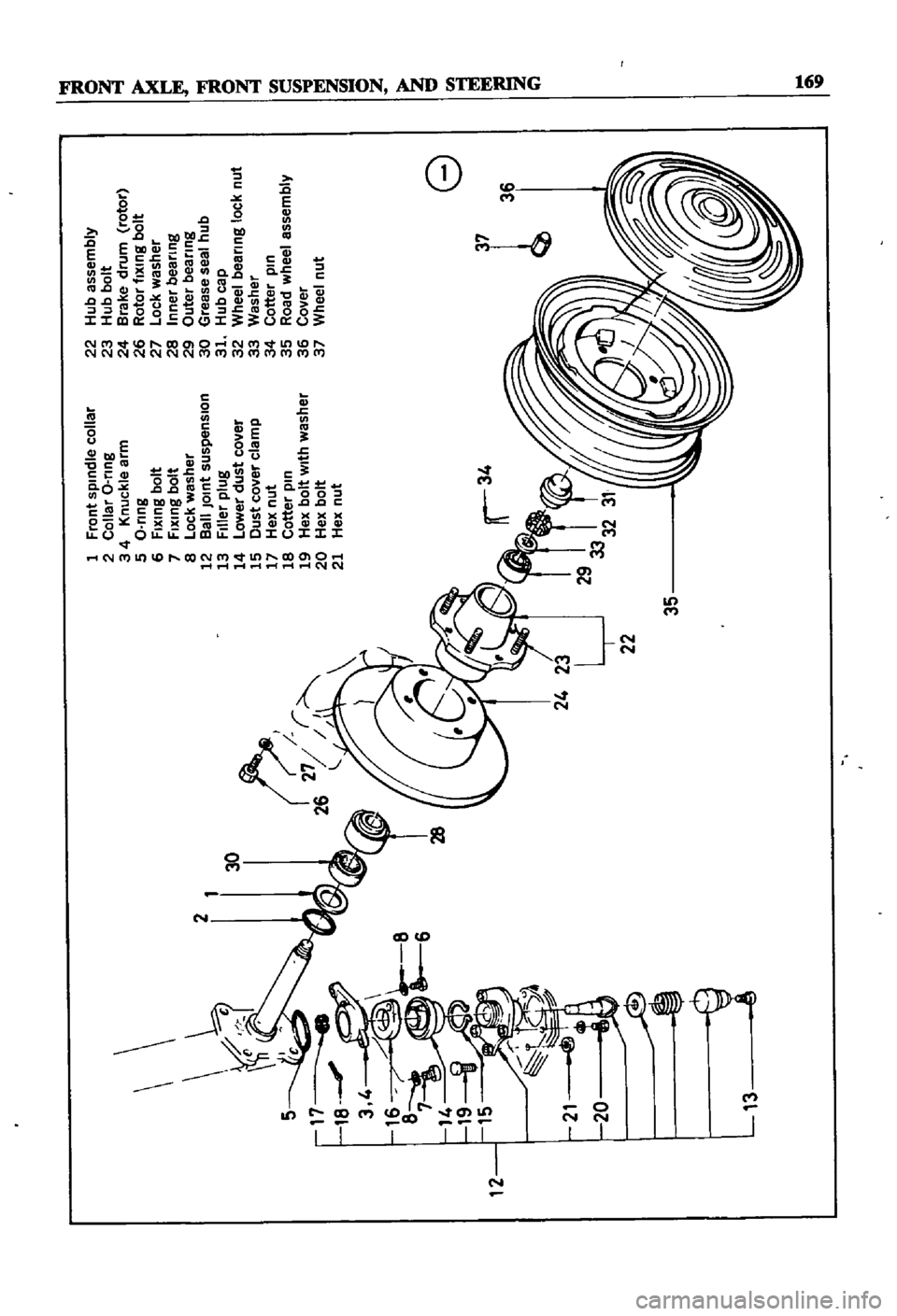
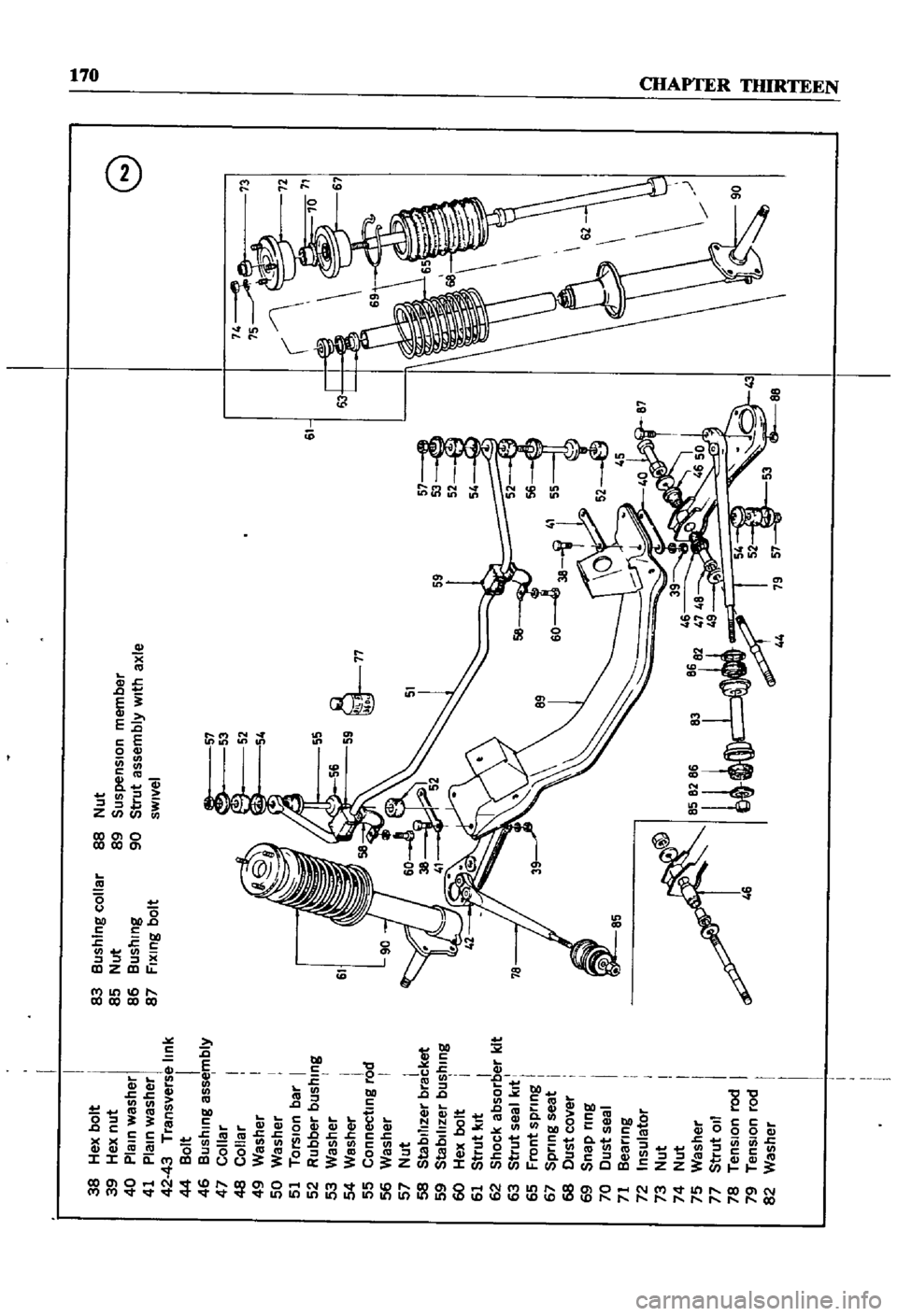
Figures
1
2
nnd
3
are
exploded
dIagrams
of
the
axle
and
suspen
SIon
system
used
FIgure
1
Illustrates
the
axle
Figure
2
shows
the
sedan
suspenSlOn
and
FIgure
3
covers
the
wagon
Front
suspensIOn
on
the
pIck
up
IS
a
double
wIShbone
mdependent
deSign
which
uses
torsIon
bars
Figure
4
IS
a
cross
sectional
view
WHEEL
HUB
AND
WHEEL
BEARING
SEDAN
AND
WAGON
Wheel
Hub
nnd
Wheel
Bearing
Removal
Sednn
aud
Wagon
1
Jack
up
the
front
of
the
vehicle
and
support
It
on
stands
2
Remove
the
wheels
3
Detach
brake
hose
connector
at
frame
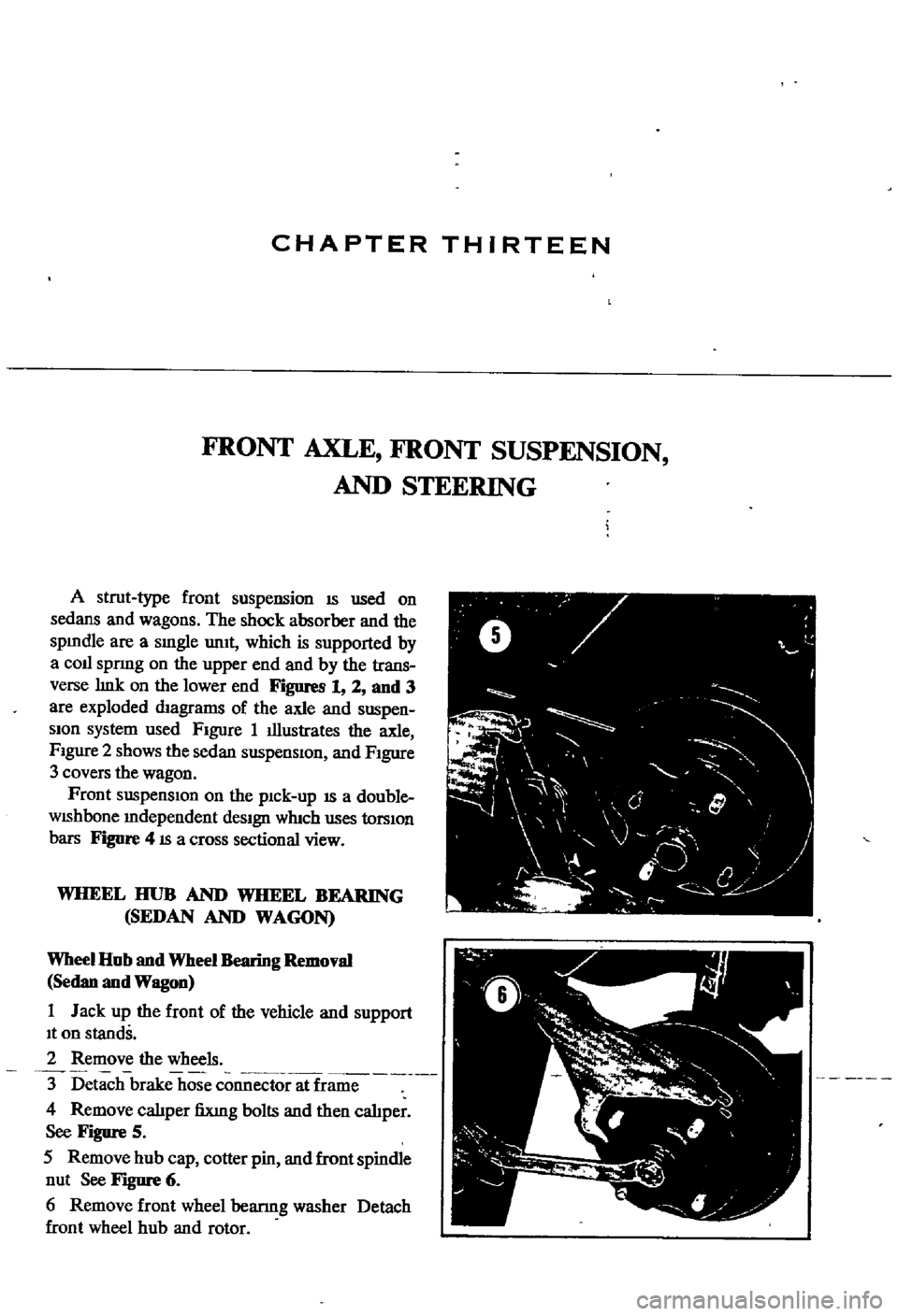
4
Remove
calIper
fiXlng
bolts
and
then
cahper
See
Figure
5
5
Remove
hub
cap
cotter
pin
and
front
spindle
nut
See
Figure
6
6
Remove
front
wheel
bearmg
washer
Detach
front
wheel
hub
and
rotor
ft
V
0
y
F
I
I
J
j
0
l
l
4
f
Page 174 of 252
1
frollt
spllldle
collar
2
Collar
O
flllg
3
4
l
lIllcl
e
artn
5
O
flIIS
6
fllllllg
bolt
7
fllllllg
bolt
8
Ocl
washer
12
aalllo1llt
SIlSpellSIOIl
13
fIller
pIllS
14
Lower
dllst
cover
15
OIlSt
cover
clatnP
17
Iellllut
18
cotter
pIli
19
ell
bolt
with
washer
20
ell
bolt
21
Iellllllt
22
ub
assetnbly
23
Iub
bOlt
24
ara
e
drutn
rotor
26
Rotor
illllllS
bOlt
27
LOC
washer
28
IlIlIer
beaflllS
29
outer
beaflnS
30
Grease
seal
hub
31
Iubcap
32
Wheel
beaflnS
10C
nut
33
Washer
34
cotter
pili
35
Road
wheel
assetnbIV
36
cover
37
Wheel
nut
11
Page 175 of 252
38
Hex
bolt
39
Hex
nut
40
Plain
washer
41
Plain
washer
42
43
Transverse
link
44
Bolt
I
46
Bushing
assembly
47
Collar
48
Collar
49
Washer
50
Washer
51
Torsion
bar
I
52
Rubber
bushing
53
Washer
I
54
Washer
55
Connecting
rod
56
Washer
I
57
Nut
i
58
Stabilizer
bracket
59
StabIlizer
bushing
60
Hex
bolt
i
61
Strut
kit
I
62
Shock
absorber
kit
63
Strut
sea
I
kit
I
65
Front
spnng
67
Spnng
seat
i
68
Dust
cover
69
Snap
rrng
I
70
Dust
seal
71
Bearing
72
Insulator
73
Nut
74
Nut
75
Washer
77
Strut
011
78
Tension
rod
79
Tension
rod
82
Washer
83
BushIng
collar
85
Nut
86
Bushing
87
FIxing
bolt
88
Nut
89
Suspension
member
90
Strut
assembly
with
axle
sWivel
0
61
61
55
59
11
63
46
8682
41
48
8S82
49
U
I
9
a
r
I
I
Page 176 of 252
38
Hex
bolt
39
Hex
nut
40
Plain
washer
41
Plain
washer
42
43
Transverse
link
44
Bolt
45
Nut
46
Bushing
assembly
47
Collar
48
Collar
49
Washer
50
Washer
51
Torsion
bar
52
Rubber
bushing
53
Washer
54
Washer
55
Connecting
rod
56
Washer
57
Nut
58
Stabilizer
bracket
59
Stabilizer
bushing
60
Hex
bolt
61
Strut
kit
62
Shock
absorber
kit
63
Strut
seal
kit
65
Front
spring
67
Spnng
seat
68
Dust
cover
69
Snap
ring
70
Dust
seal
71
Bearing
72
Insulator
73
Nut
74
Nut
75
Washer
80
Tension
rod
81
TenSion
rod
82
Washer
83
Bushing
collar
85
Nut
86
Bushing
0
G
57
53
l
Fl
52
72
l
54
61
55
63
67
rI
l
56
c
l
59
rI
l
77
rI
l
51
57
59
53
46
8682
47
48
u