Page 49 of 252

44
CHAPTER
SIX
@
@
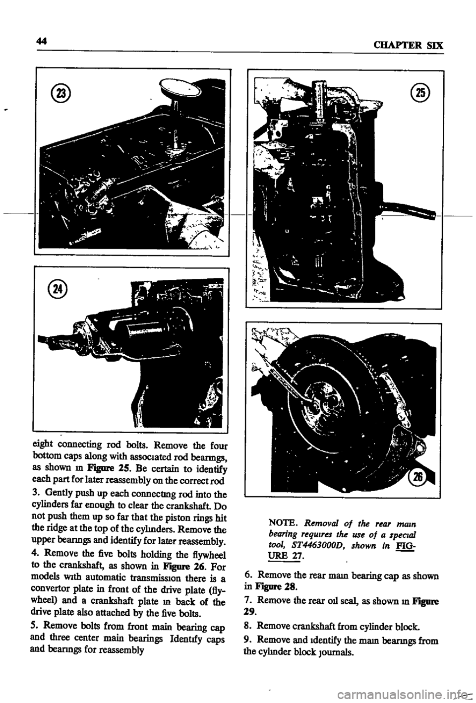
eight
connecting
rod
bolts
Remove
the
four
bottom
caps
along
with
assoc1ated
rod
beanngs
as
shown
m
Figure
25
Be
certain
to
identify
each
part
for
later
reassembly
on
the
correct
rod
3
Gently
push
up
each
connecting
rod
into
the
cylinders
far
enough
to
clear
the
crankshaft
Do
not
push
them
up
so
far
that
the
piston
rings
hit
the
ridge
at
the
top
of
the
cyImders
Remove
the
upper
beanngs
and
identify
for
later
reassembly
4
Remove
the
five
bolts
holding
the
flywheel
to
the
crankshaft
as
shown
in
Figure
26
For
models
Wlth
automatic
transmisslOn
there
is
a
convertor
plate
in
front
of
the
drive
plate
fly
wheel
and
a
crankshaft
plate
m
back
of
the
drive
plate
also
attached
by
the
five
bolts
5
Remove
bolts
from
front
main
bearing
cap
and
three
center
main
bearings
Identtfy
caps
and
beanngs
for
reassembly
@
NOTE
Removal
of
the
rear
mam
bearing
requires
the
use
of
a
specuzl
tool
ST4463000D
shown
in
f
Q
URE
27
6
Remove
the
rear
mam
bearing
cap
as
shown
in
Figure
28
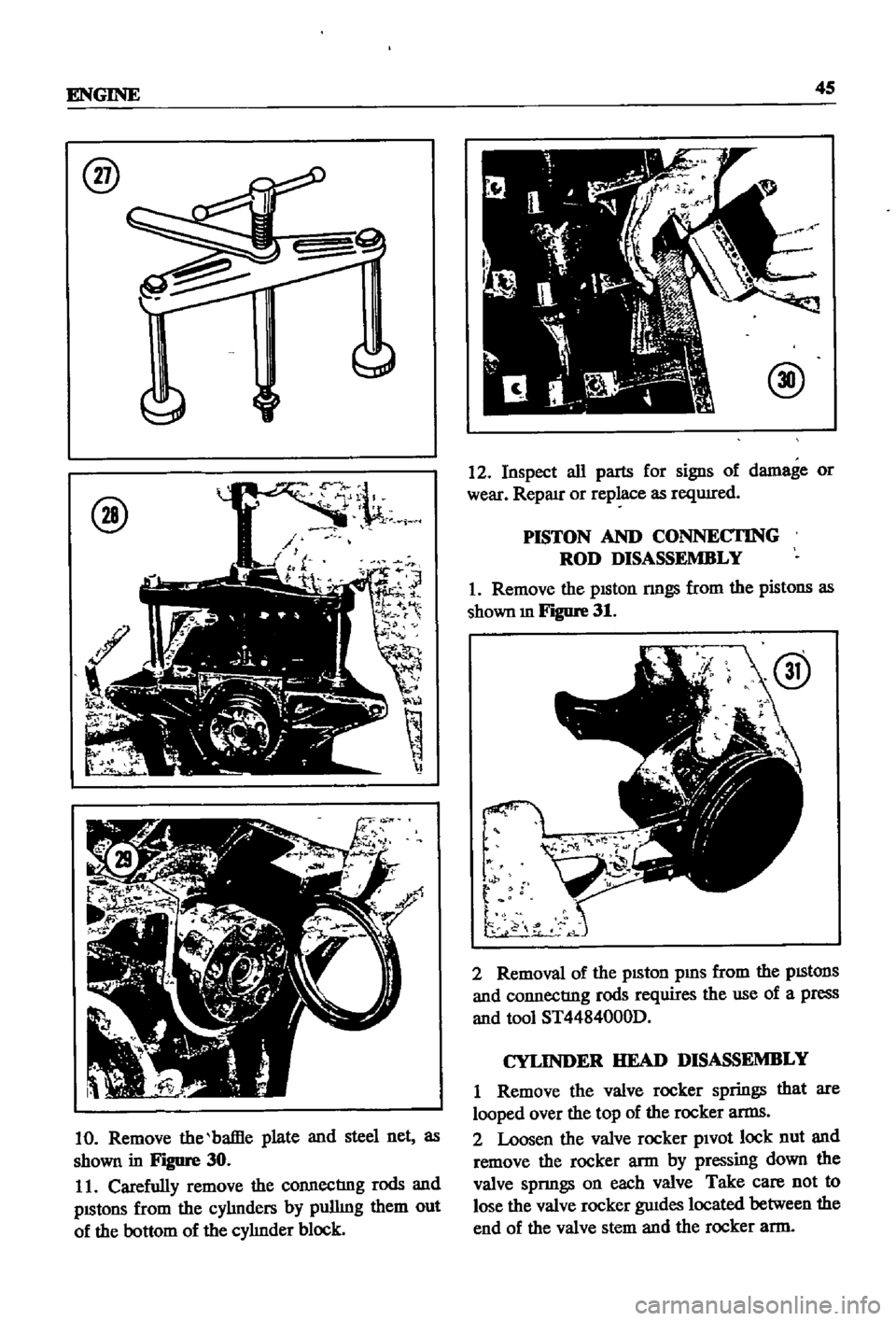
7
Remove
the
rear
011
seal
as
shown
m
Figure
29
8
Remove
crankshaft
from
cylinder
block
9
Remove
and
1dentify
the
mam
beanngs
from
the
cyhnder
block
JOurnals
Page 50 of 252
ENGINE
45
@
@
10
Remove
the
baffle
plate
and
steel
net
as
shown
in
Figure
30
11
Carefully
remove
the
connecting
rods
and
pIStons
from
the
cyhnders
by
pulling
them
out
of
the
bottom
of
the
cyhnder
block
@
12
Inspect
all
parts
for
signs
of
damage
or
wear
Repau
or
replace
as
reqUIred
PISTON
AND
CONNECI1NG
ROD
DISASSEMBLY
1
Remove
the
piston
nngs
from
the
pistons
as
shown
m
Figure
31
t
p
t
r
d
2
Removal
of
the
pISton
pms
from
the
pIStonS
and
connecting
rods
requires
the
use
of
a
press
and
tool
ST4484000D
CYLINDER
HEAD
DISASSEMBLY
I
Remove
the
valve
rocker
springs
that
are
looped
over
the
top
of
the
rocker
arms
2
Loosen
the
valve
rocker
pivot
lock
nut
and
remove
the
rocker
arm
by
pressing
down
the
valve
spnngs
on
each
valve
Take
care
not
to
lose
the
valve
rocker
gwdes
located
between
the
end
of
the
valve
stem
and
the
rocker
arm
Page 51 of 252

46
CHAPTER
SIX
CAUTION
When
removing
camshaft
use
ex
treme
care
not
to
scratch
the
cam
bushings
Be
certam
to
leave
the
cam
shaft
bushings
Intact
so
as
not
to
get
them
out
of
al
gnment
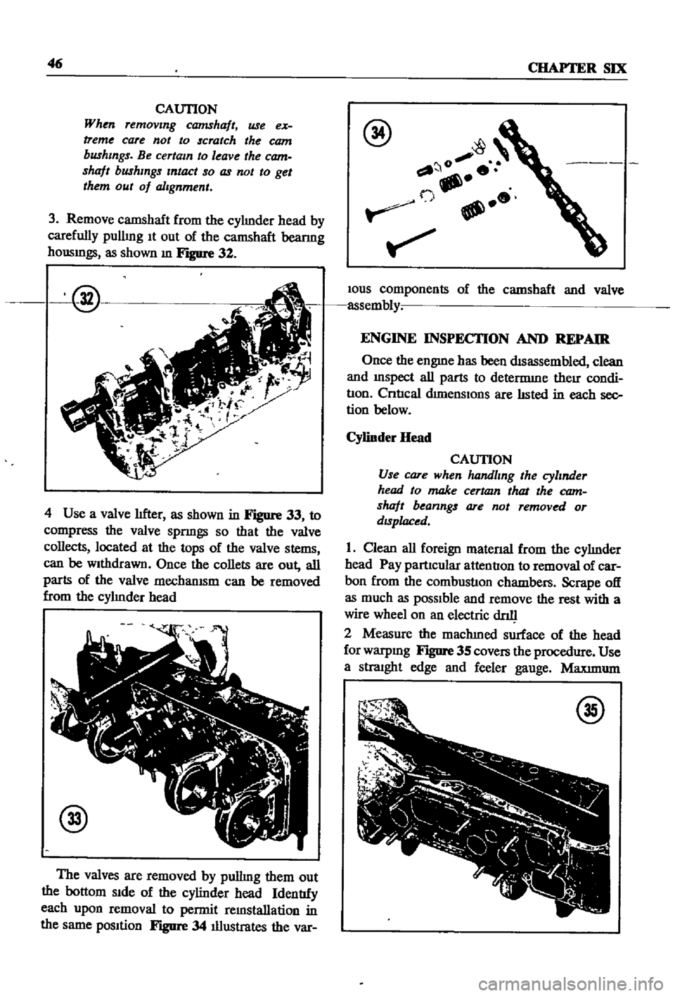
3
Remove
camshaft
from
the
cylmder
head
by
carefully
pullmg
It
out
of
the
camshaft
beanng
housmgs
as
shown
m
Figure
32
@
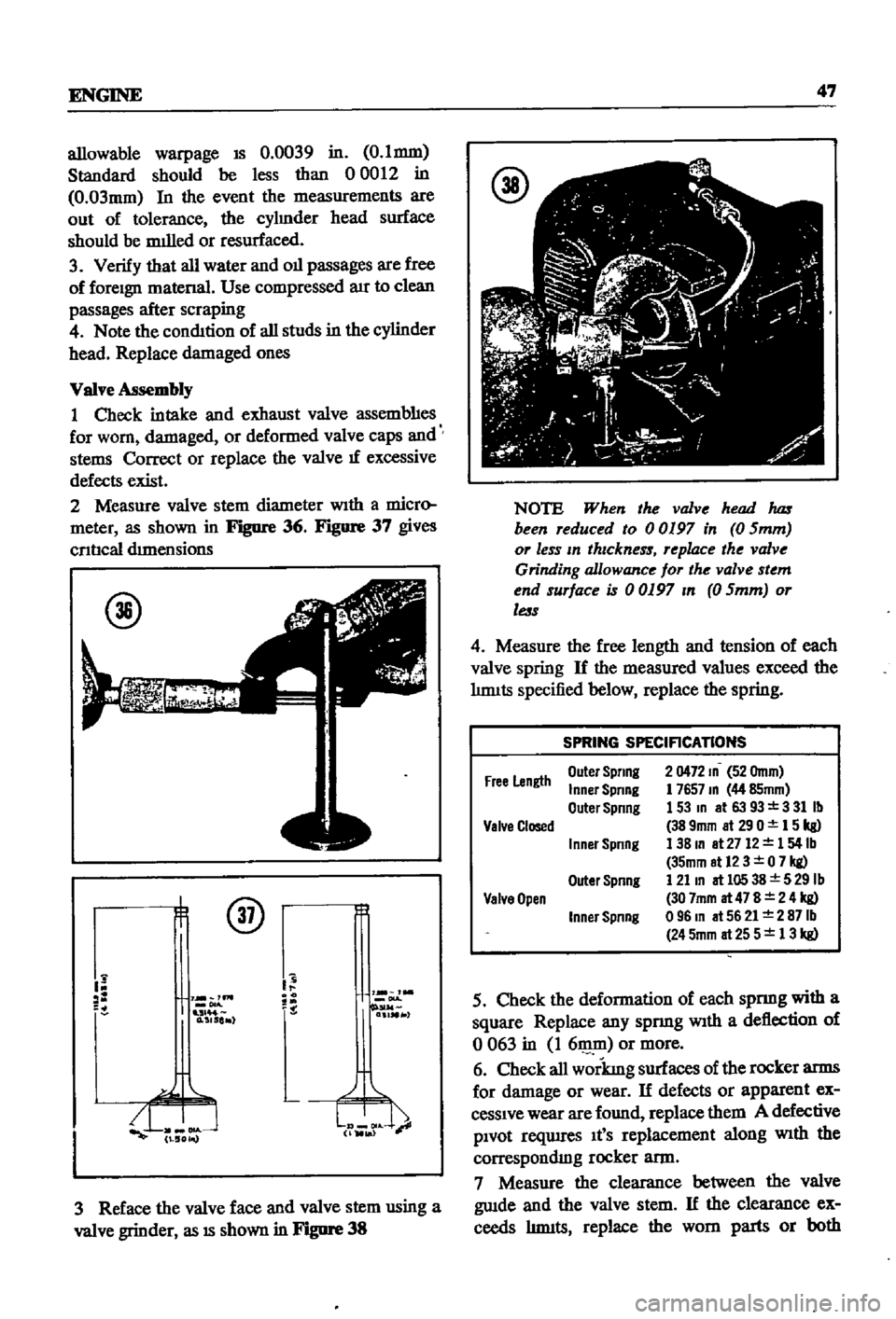
4
Use
a
valve
hfter
as
shown
in
Figure
33
to
compress
the
valve
spnngs
so
that
the
valve
collects
located
at
the
tops
of
the
valve
stems
can
be
wIthdrawn
Once
the
collets
are
out
all
parts
of
the
valve
mechamsm
can
be
removed
from
the
cylmder
head
@
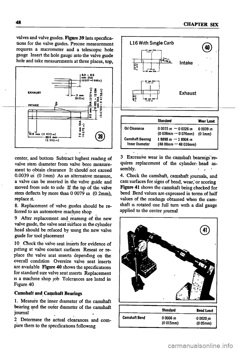
The
valves
are
removed
by
pullmg
them
out
the
bottom
SIde
of
the
cylinder
head
IdentIfy
each
upon
removal
to
permit
remstallation
in
the
same
posItion
Figure
34
Illustrates
the
var
@
o
o
IOUS
components
of
the
camshaft
and
valve
assembly
ENGINE
INSPECTION
AND
REPAIR
Once
the
engme
has
been
dIsassembled
clean
and
mspect
all
parts
to
determme
theIr
condi
tIon
CntIcal
dunenslOns
are
hsted
in
each
sec
tion
below
Cylinder
Head
CAUTION
Use
care
when
handling
the
cylinder
head
to
make
certam
that
the
cam
shaft
beanngs
are
not
removed
or
dIsplaced
1
Clean
all
foreign
matenal
from
the
cylmder
head
Pay
partIcular
attentIon
to
removal
of
car
bon
from
the
combustIon
chambers
Scrape
off
as
much
as
pOSSIble
and
remove
the
rest
with
a
wire
wheel
on
an
electric
dn11
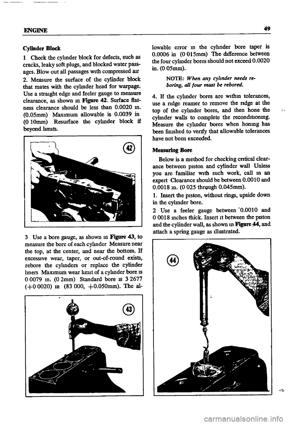
2
Measure
the
machIned
surface
of
the
head
for
warpmg
FIgUre
35
covers
the
procedure
Use
a
StraIght
edge
and
feeler
gauge
Maxunum
@
Page 52 of 252

ENGINE
47
allowable
warpage
IS
0
0039
in
0
I
mm
Standard
should
be
less
than
0
0012
in
O
03mm
In
the
event
the
measurements
are
out
of
tolerance
the
cylmder
head
surface
should
be
milled
or
resurfaced
3
Verify
that
all
water
and
011
passages
are
free
of
foreign
matena
Use
compressed
aIr
to
clean
passages
after
scraping
4
Note
the
condition
of
all
studs
in
the
cylinder
head
Replace
damaged
ones
Valve
Assembly
I
Check
intake
and
exhaust
valve
assembhes
for
worn
damaged
or
deformed
valve
caps
and
stems
Correct
or
replace
the
valve
If
excessive
defects
exist
2
Measure
valve
stem
diameter
WIth
a
micro
meter
as
shown
in
Fignre
36
Figure
37
gives
cnncal
drmensions
@
@
Y
lm
1
0
515
r
3
Reface
the
valve
face
and
valve
stem
using
a
valve
grinder
as
18
shown
in
Fignre
38
NOTE
When
the
valve
head
1uzs
been
reduced
to
00197
in
0
Smm
or
less
In
thIckness
replace
the
valve
Grinding
allowance
for
the
valve
stem
end
surface
is
00197
In
0
Smm
or
less
4
Measure
the
free
length
and
tension
of
each
valve
spring
If
the
measured
values
exceed
the
hnuts
specified
below
replace
the
spring
SPRING
SPECIFICATIONS
Free
Length
Outel
Spring
Inner
Spring
Outer
Spring
2
0472
10
52
Omm
1
765710
44
85mm
153m
at6393
331Ib
389mm
at290
15kg
138m
at
2712
154lb
35mm
at12
3
0
7
kg
121
10
at
105
38
5
29
Ib
30
7mm
at
47
8
2
4
kg
09610
at5621
2871b
245mm
at
25
5
13
kg
Valve
Closed
I
nner
Spring
Outer
Spnng
Valve
Open
Inner
Spnng
5
Check
the
deformation
of
each
spnng
with
a
square
Replace
any
spnng
WIth
a
deflection
of
o
063
in
I
611lID
or
more
6
Check
all
workmg
surfaces
of
the
rocker
arms
for
damage
or
wear
If
defects
or
apparent
ex
cessIve
wear
are
found
replace
them
A
defective
PIvot
reqwres
It
S
replacement
along
WIth
the
correspondIng
rocker
ann
7
Measure
the
clearance
between
the
valve
gwde
and
the
valve
stem
If
the
clearance
ex
ceeds
hnuts
replace
the
worn
parts
or
both
Page 53 of 252

48
CHAPTER
SIX
valves
and
valve
guIdes
Figure
39
hsts
specifica
tions
for
the
valve
gwdes
PreCIse
measurement
reqwres
a
nncrometer
and
a
telescopIC
hole
gauge
Insert
the
hole
gauge
mto
the
valve
gwde
hole
and
take
measurements
at
three
places
top
u
mm
OIA
CO
527
o
as
n
C
S
EXHAUST
3mm
0
0
111110
0
I
J
aDo
INTAKE
10
f
tl
T1
I
f
I
J
c
c
E
E
@
108
mm
Co
425
od
o
mm
2
32
ln
center
and
bottom
Subtract
hIghest
readmg
of
valve
stem
dIameter
from
valve
bore
measure
ment
to
obtain
clearance
It
should
not
exceed
0
0039
m
0
Imm
As
an
alternatIve
measure
a
valve
can
be
mserted
in
the
valve
guide
and
moved
from
SIde
to
SIde
If
the
tip
of
the
vaJ
ve
stem
deflects
by
more
than
0
0079
m
0
2mm
replace
It
8
Replacement
of
valve
gwdes
should
be
re
ferred
to
an
automotive
mac
rne
shop
9
After
replacement
anI
reannng
of
the
new
valve
guIde
the
valve
seat
surface
m
the
cylmder
head
should
be
refaced
by
usrng
the
new
valve
gwde
for
tool
placement
10
Check
the
valve
seat
inserts
for
evidence
of
plttmg
at
valve
contact
surfaces
Reseat
or
re
place
the
valve
seat
mserts
depending
on
the
overall
condItion
Oversize
valve
seat
inserts
are
available
Figure
40
shows
the
specificatIons
for
standard
sIZe
valve
seat
mserts
Replacement
IS
a
machme
shop
Job
Tolerances
are
listed
in
FIgure
40
Camshaft
and
ClIIll8haft
Bearings
1
Measure
the
inner
dIameter
of
the
camshaft
bearing
and
the
ouier
dIameter
of
the
camshaft
journal
2
Detenmne
the
actual
clearances
and
com
pare
them
to
the
specifications
followmg
Ll6
With
Single
Carb
@
Intake
Exhaust
Od
Clearance
Standard
00015
10
0
0026
10
00381010
0
0761010
1
8898
10
1
8904
rn
48
001010
48
0161010
Wear
Lrmll
o
0039
rn
011010
Camshaft
Beanng
Inner
Olameter
3
ExceSSIve
wear
in
the
camshaft
beanngs
re
quires
replacement
of
the
cyhnderl
head
as
sembly
4
Check
the
camshaft
camshaft
JOurnals
and
cam
surfaces
for
signs
of
bend
wear
or
scoring
Figure
41
shows
the
camshaft
being
checked
for
bend
Bend
values
are
expressed
in
terms
of
half
values
of
the
readmgs
obtamed
when
the
cam
shaft
15
rotated
one
full
turn
WIth
a
dial
gauge
applied
to
the
center
Journal
@
Camshaft
Bend
standard
o
0006
10
00151010
Bend
Lrmll
00020
rn
0
051010
Page 54 of 252

ENGINE
49
Cylinder
Block
1
Check
the
cylmder
block
for
defects
such
as
cracks
leaky
soft
plugs
and
blocked
water
pass
ages
Blowout
all
passages
With
compressed
air
2
Measure
the
surface
of
the
cylinder
block
that
mates
with
the
cyhnder
head
for
warpage
Use
a
straight
edge
and
feeler
gauge
to
measure
clearance
as
shown
m
Figure
42
Surface
flat
ness
clearance
should
be
less
than
0
0020
m
0
05mm
Maxunum
allowable
is
0
0039
in
010mm
Resurface
the
cyhnder
block
if
beyond
hnnts
@
3
Use
a
bore
gauge
as
shown
m
Figure
43
to
measure
the
bore
of
each
cyhnder
Measure
near
the
top
at
the
center
and
near
the
bottom
If
excessive
wear
taper
or
out
of
round
exists
rebore
the
cyhnders
or
replace
the
cylinder
hners
Maxunum
wear
hnnt
of
a
cyhnder
bore
IS
o
0079
m
0
2mm
Standard
bore
IS
3
2677
0
0020
m
83
000
0
050mm
The
al
@
lowable
error
m
the
cyhnder
bore
taper
is
0
0006
in
0015mm
The
difference
between
the
four
cyhnder
bores
should
not
exceed
0
0020
in
0
05mm
NOTE
When
any
cylmder
needs
re
boring
all
foUT
must
be
rebored
4
If
the
cyhnder
bores
are
Wlthm
tolerances
use
a
ndge
reamer
to
remove
the
ndge
at
the
top
of
the
cyhnder
bores
and
then
hone
the
cyhnder
walls
to
complete
the
recolllhuonmg
Measure
the
cyhnder
bores
when
honmg
has
been
finished
to
venfy
that
allowable
tolerances
have
not
been
exceeded
Measuring
Bore
Below
is
a
method
for
checking
cntical
clear
ance
between
piston
and
cylinder
wall
Unless
you
are
familiar
With
such
work
call
m
an
expert
Clearance
should
be
between
0
0010
and
0
0018
m
0025
thrQugh
0
045mm
1
Insert
the
pISton
without
rings
upside
down
in
the
cyhnder
bore
2
Use
a
feeler
gauge
between
0
0010
and
00018
mches
thick
Insert
It
between
the
pISton
and
the
cylinder
wall
as
shown
m
Figure
and
attach
a
spring
gauge
as
illustrated
@
Page 55 of 252

50
CHAPTER
SIX
3
Pull
up
on
the
spnng
scale
If
the
force
re
qurred
to
pull
the
feeler
gauge
out
IS
more
than
3
3
lbs
or
less
than
0
44
Ibs
the
piston
skirt
IS
either
too
large
or
small
for
the
cyhnder
and
must
be
replaced
With
a
pISton
of
the
proper
size
EIther
that
or
the
cyhnder
must
be
rebored
or
a
new
cyhnder
hner
mstalled
Piston
Piston
Pin
and
Piston
Ring
1
Inspect
all
parts
carefully
for
signs
of
clups
cracks
and
general
wear
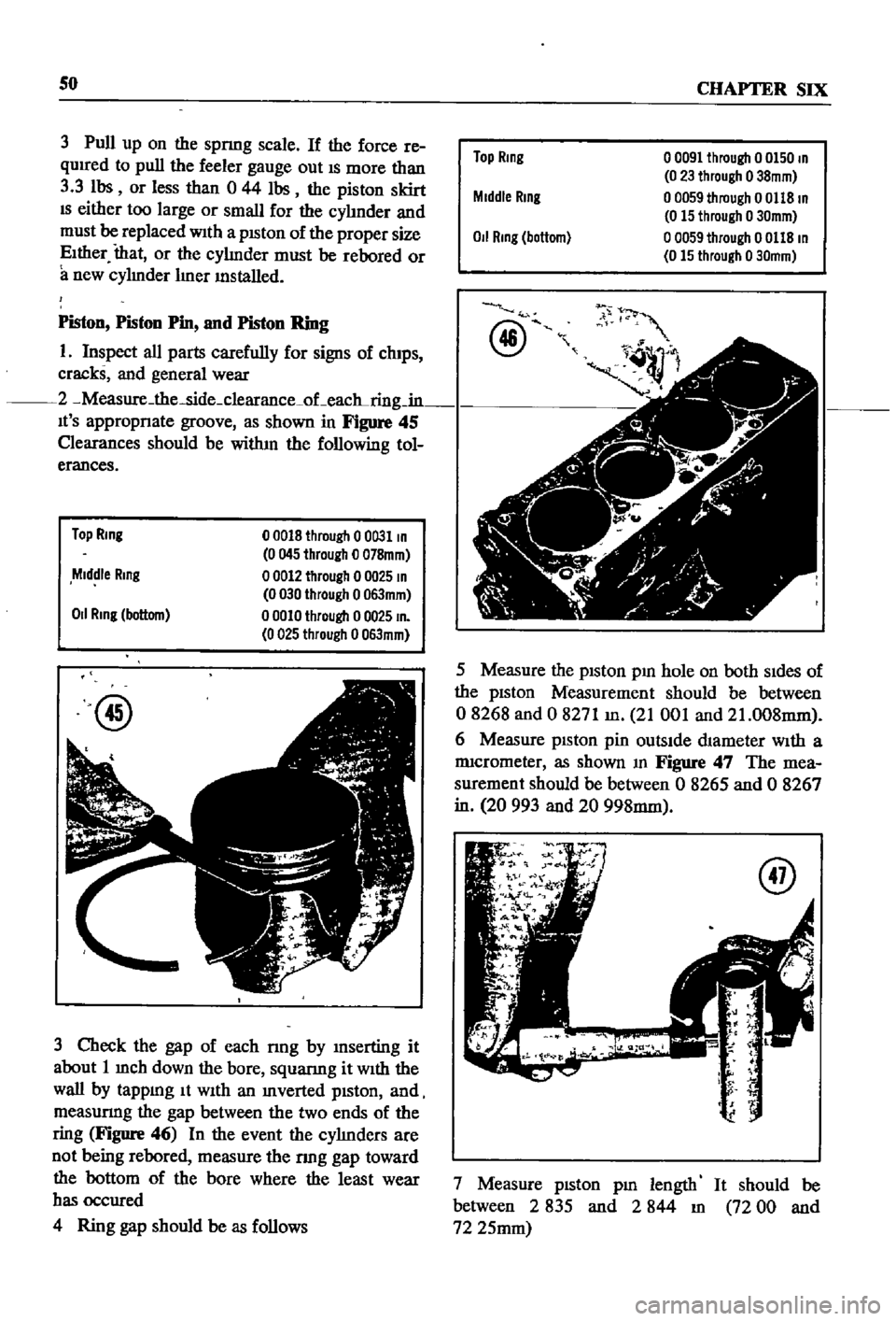
2
Measure
the
side
clearance
oLeac
ring
in
It
S
appropnate
groove
as
shown
in
Figure
45
Clearances
should
be
witlun
the
following
tol
erances
Top
Ring
00018
through
00031
In
0045
through
0
078mm
00012
through
0
0025
In
0030
through
0063mm
00010
through
0
0025
In
0025
through
0063mm
Middle
Ring
011
Ring
bottom
@
3
Check
the
gap
of
each
nng
by
mserting
it
about
1
mch
down
the
bore
squanng
it
With
the
wall
by
tappmg
It
WIth
an
mverted
pIston
and
measunng
the
gap
between
the
two
ends
of
the
ring
Figure
46
In
the
event
the
cyhnders
are
not
being
rebored
measure
the
nng
gap
toward
the
bottom
of
the
bore
where
the
least
wear
has
occured
4
Ring
gap
should
be
as
follows
Top
Ring
00091
through
0
0150
In
0
23
through
o
38mm
o
0059
through
0
0118
In
0
15
through
0
30mm
o
0059
through
0
0118
In
0
15
through
0
30mm
Middle
Rmg
0
1
Rmg
bottom
@
fJ
t
1
v
5
Measure
the
pIston
pm
hole
on
both
SIdes
of
the
pIston
Measurement
should
be
between
08268
and
0
8271
m
21
001
and
21
008mm
6
Measure
pISton
pin
outsIde
dIameter
With
a
nucrometer
as
shown
m
Figure
47
The
mea
surement
should
be
between
0
8265
and
0
8267
in
20
993
and
20
998mm
7
Measure
pIston
pm
length
It
should
be
between
2
835
and
2
844
m
72
00
and
72
25mm
Page 56 of 252

ENGINE
51
8
Figure
48
shows
the
pm
bemg
mserted
to
make
certam
that
It
can
be
pressed
m
at
room
temperature
by
hand
Piston
pm
clearance
to
piston
pm
should
be
between
0
0003
and
0
0004
m
0008
and
0
01Omm
NOTE
The
piston
pin
IS
fitted
to
the
connecting
rod
with
a
fitting
force
of
from
1
to
3
tons
of
pressure
Connecting
Rod
1
Inspect
all
connectmg
rods
for
flaws
or
obVIOUS
damage
2
Check
for
proper
alignment
as
shown
m
Fig
ure
49
RealIgn
as
necessary
ThIS
can
be
done
by
an
automotive
maclune
shop
Maxrmum
allowable
bend
m
the
connecting
rods
IS
0
0020
m
0
05mm
per
3
94
m
of
connecting
rod
length
@
3
Defects
m
the
piston
pm
hole
reqwre
replace
ment
of
the
connectmg
rod
Select
new
ones
so
that
weight
dIfference
between
new
and
old
IS
wlthm
0212
oz
6
gr
4
Install
beanngs
m
the
crankshaft
end
of
all
rods
Mount
the
rods
on
the
crankshaft
and
replace
beanngs
and
rod
caps
Install
bolts
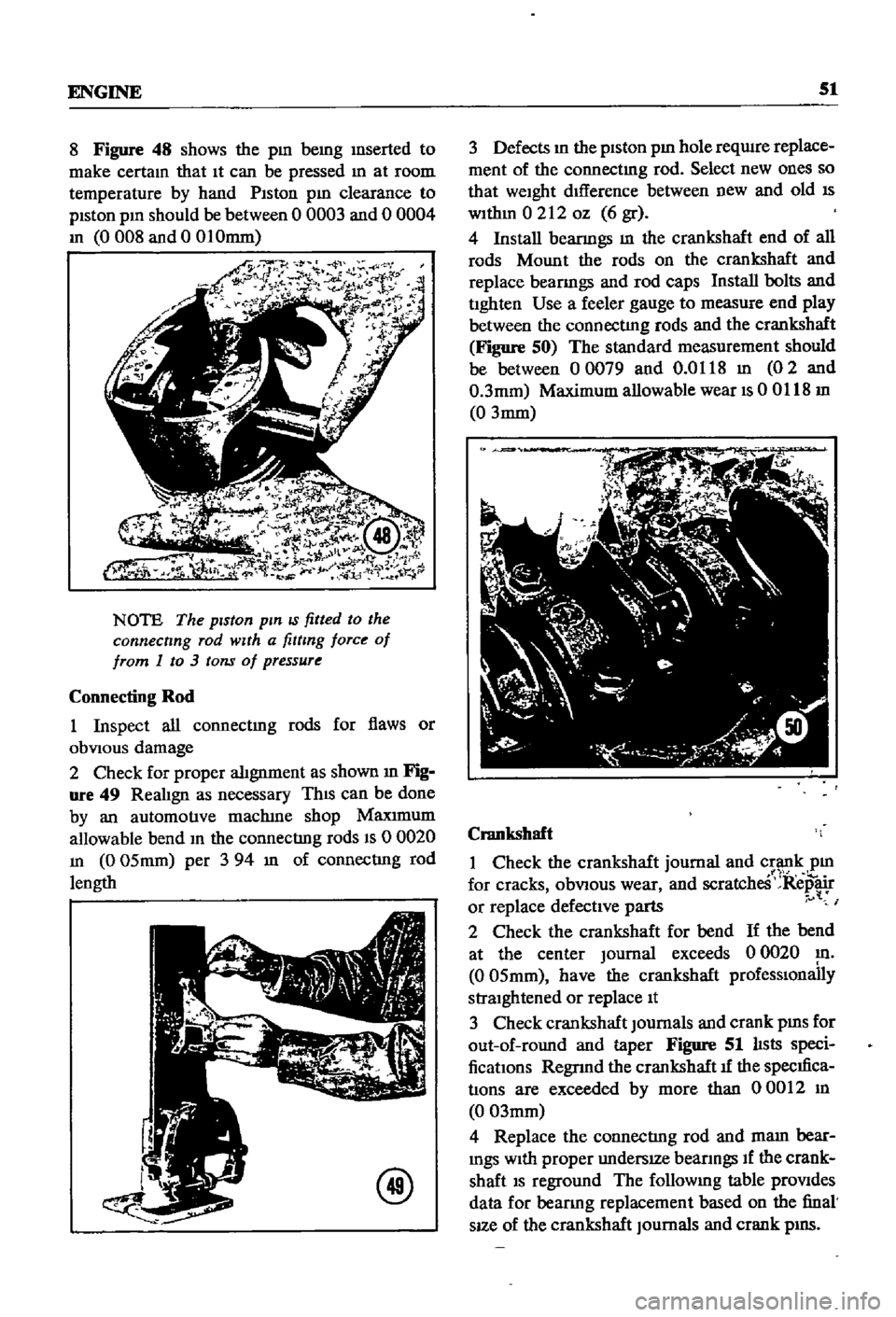
and
tighten
Use
a
feeler
gauge
to
measure
end
play
between
the
connecting
rods
and
the
crankshaft
Figure
50
The
standard
measurement
should
be
between
00079
and
0
0118
m
02
and
0
3mm
Maximum
allowable
wear
IS
00118
m
0
3mm
Crankshaft
1
Check
the
crankshaft
journal
and
crank
pm
1
1
for
cracks
obVIOUS
wear
and
scratcheS
Repair
or
replace
defective
parts
I
2
Check
the
crankshaft
for
bend
If
the
bend
at
the
center
Journal
exceeds
0
0020
m
0
05mm
have
the
crankshaft
prOfeSSIOnally
straightened
or
replace
It
3
Check
crankshaft
Journals
and
crank
pms
for
out
of
round
and
taper
Figure
51
lIsts
speci
fications
Regnnd
the
crankshaft
1f
the
specIfica
tions
are
exceeded
by
more
than
00012
m
0
03mm
4
Replace
the
connecting
rod
and
mam
bear
mgs
With
proper
undersIZe
beanngs
If
the
crank
shaft
IS
reground
The
followmg
table
prOVides
data
for
beanng
replacement
based
on
the
final
sIZe
of
the
crankshaft
Journals
and
crank
pIllS