Page 129 of 252
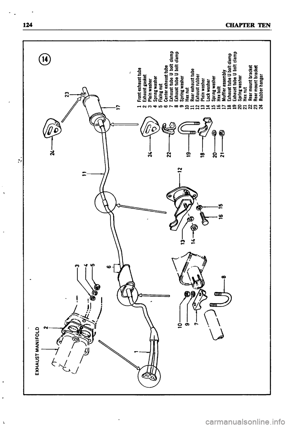
2
@
24
11
3
10
9
r
7
8
JI
4
J
c
U
12
24
22
19
18
@
20
ta
21
1
frontBxhaust
tube
2
Exheust
gasket
3
Plein
wesher
4
Spnng
wesher
5
fixing
nut
6
Center
exhaust
tube
7
Exhaust
tube
U
bolt
clamp
8
Exhaust
tube
U
bolt
clamp
9
Spring
wesher
10
Hex
nut
11
Reer
exheusttube
12
Exhaust
rubber
13
Plain
washer
14
Lock
washer
15
Spnng
washer
16
Hex
bolt
17
Muffler
essembly
18
Exhaust
tube
U
bolt
clamp
19
Exhaust
tube
U
bolt
clamp
20
spring
wesher
21
Hex
nut
22
Rear
mount
bracket
23
Rear
mount
brecket
24
Rubber
henger
i
Page 130 of 252
22
rnL
T
II
19
2
16
rr
I
II
l
r
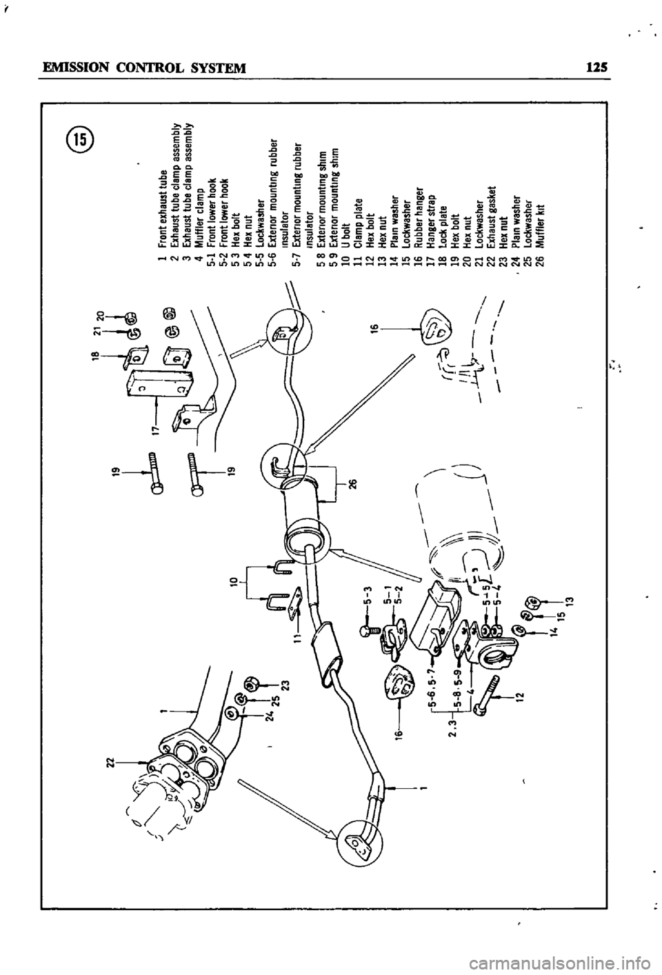
@
1
Front
exhaust
tube
2
Exhaust
tube
clamp
assembly
3
Exhaust
tube
clemp
assembly
4
Muffler
clamp
5
1
Front
lower
hook
5
2
Front
lower
hook
5
3
Hex
bolt
5
4
Hex
nut
5
5
Lockwasher
5
6
Extenor
mounting
rubber
Insulator
5
7
Extenor
mounting
rubber
Insulator
5
8
Extenor
mounting
shim
5
9
Extenor
mounting
shim
10
U
bolt
11
Clamp
plate
12
Hex
bolt
13
Hex
nut
14
Plain
washer
15
lockwasher
16
Rubber
hanger
17
Hanger
strap
18
lock
plate
19
Hex
bolt
20
Hex
nut
21
lockwasher
22
Exhaust
gasket
23
Hex
nut
24
Plain
washer
25
lockwasher
26
Muffler
kit
l
o
o
t
I
N
III
Page 131 of 252
126
CHAPTER
TEN
@
r
Removal
Pick
up
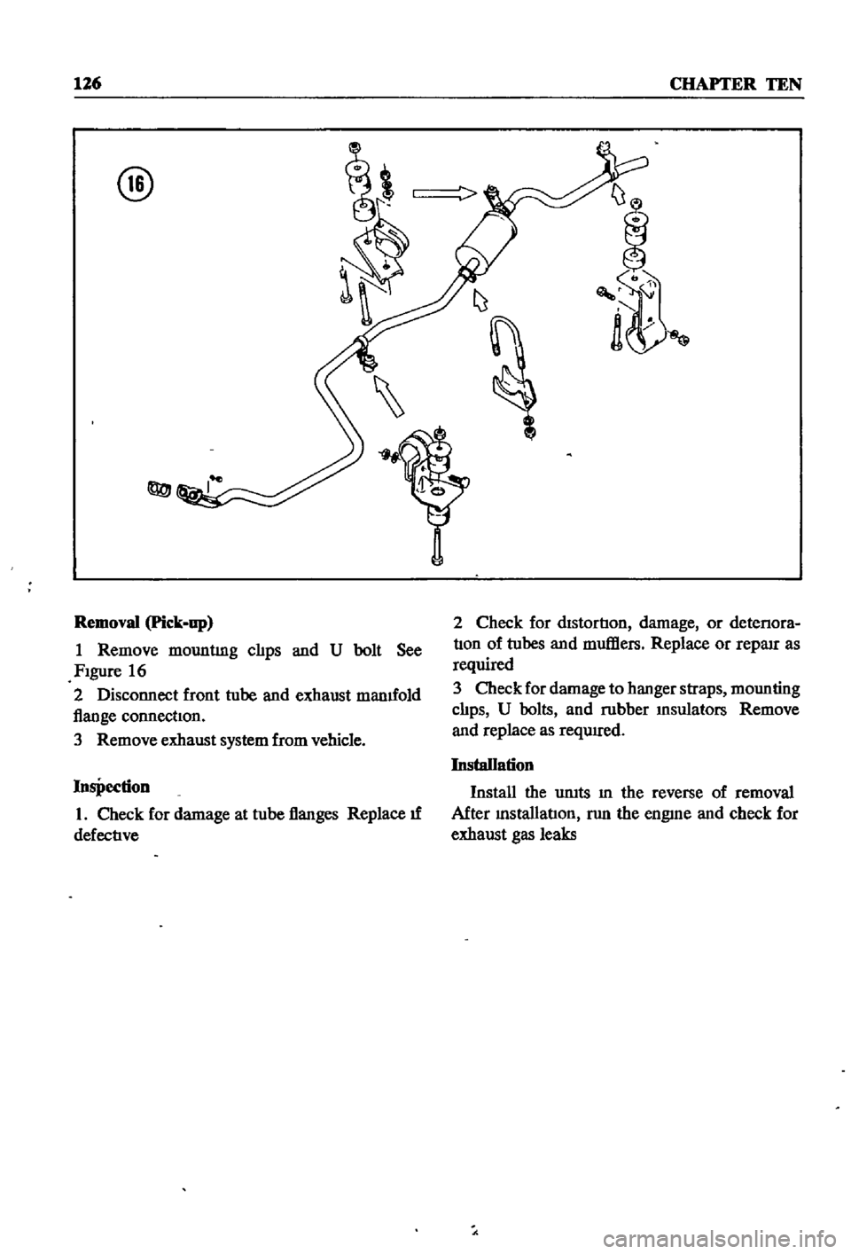
1
Remove
mountlng
clIps
and
U
bolt
See
FIgure
16
2
Disconnect
front
tube
and
exhaust
manuold
flange
connectIon
3
Remove
exhaust
system
from
vehicle
Inspection
1
Check
for
damage
at
tube
flanges
Replace
u
defectIve
2
Check
for
dIstortIon
damage
or
detenora
tIon
of
tubes
and
mufHers
Replace
or
reparr
as
required
3
Check
for
damage
to
hanger
straps
mounting
clIps
U
bolts
and
rubber
Insulators
Remove
and
replace
as
requrred
Installation
Install
the
umts
m
the
reverse
of
removal
After
InstallatIon
nm
the
engme
and
check
for
exhaust
gas
leaks
Page 132 of 252

CHAPTER
ELEVEN
CLUTCH
TRANSMISSION
AND
DRIVESHAFf
CLUTCH
i
es
ription
Datsun
uses
a
single
dry
dtsc
clutch
with
dIaphragm
spring
The
major
components
are
clutch
cover
pressure
plate
dIaphragm
spring
and
WIre
nngs
The
clutch
dISC
has
riveted
plates
on
both
surfaces
and
coll
spnngs
arranged
in
a
link
The
coll
springs
absorb
shock
to
soften
and
smooth
clutch
engagement
Figure
1
next
page
is
an
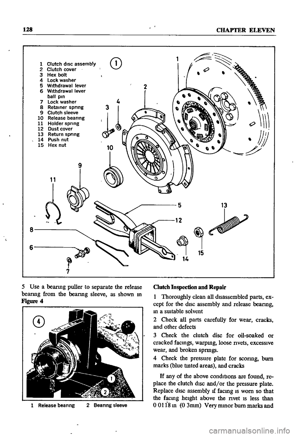
exploded
diagram
of
the
clutch
assembly
Clutch
Removal
The
transmIssion
must
be
separated
from
the
engme
to
remove
tlte
clutch
assembly
This
can
be
done
by
removmg
the
transmISSIon
and
engme
from
the
vehicle
as
a
umt
or
by
remoVIng
the
transmiSSIon
separately
Removal
of
the
engine
and
transmissIOn
IS
descnbed
In
Chapter
Six
Removal
of
the
transmISSIon
only
IS
descnbed
later
in
tills
chapter
Outcb
Disassembly
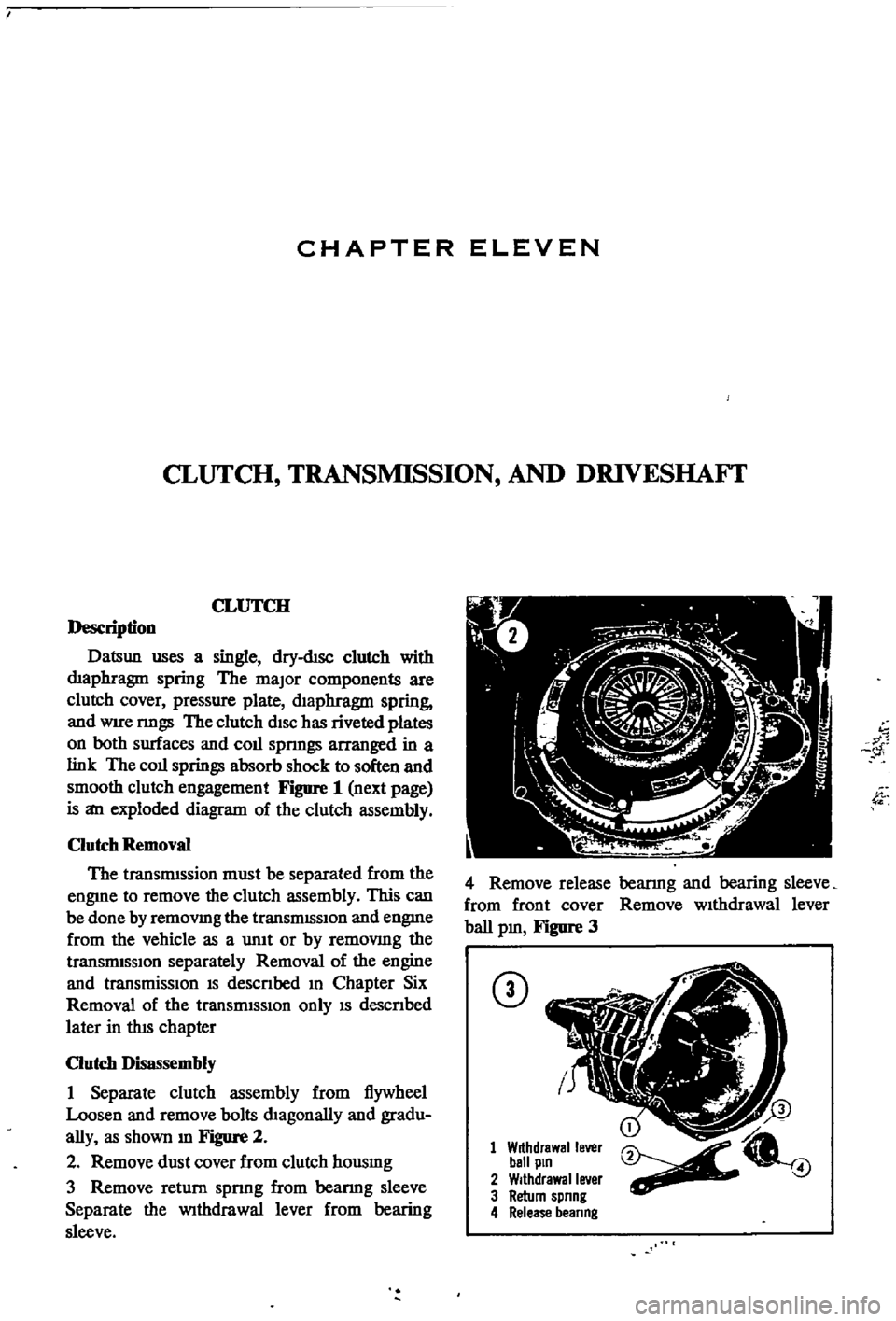
1
Separate
clutch
assembly
from
flywheel
Loosen
and
remove
bolts
dIagonally
and
gradu
ally
as
shown
m
Figure
2
2
Remove
dust
cover
from
clutch
housmg
3
Remove
return
spnng
from
beanng
sleeve
Separate
the
Withdrawal
lever
from
bearing
sleeve
w
1
4
Remove
release
bearmg
and
bearing
sleeve
from
front
cover
Remove
wIthdrawal
lever
ball
pm
Figure
3
CD
1
Withdrawal
lever
ball
pin
2
Withdrawal
lever
3
Return
spnng
4
Release
beanng
4
Page 133 of 252
128
CHAPTER
ELEVEN
1
Clutch
disc
assembly
2
Clutch
cover
3
Hex
bolt
4
Lock
washer
5
Withdrawal
lever
6
Withdrawal
lever
ball
pin
7
Lock
washer
8
Retainer
spnng
9
Clutch
sleeve
10
Release
bearing
11
Holder
spring
12
Dust
cover
13
Return
spring
14
Push
nut
15
Hex
nut
CD
9
11
8
6
7
1
Release
beanng
2
Beanng
sleeve
2
5
13
12
15
14
Clutch
Inspection
and
Repair
1
Thoroughly
clean
all
dISassembled
parts
ex
cept
for
the
dISc
assembly
and
release
bearmg
In
a
SUItable
solvent
2
Check
all
parts
carefully
for
wear
cracks
and
other
defects
3
Check
the
clutch
disc
for
oil
soaked
or
cracked
faCIngs
warpmg
loose
nvets
exceSSIve
wear
and
broken
spnngs
4
Check
the
pressure
plate
for
sconng
bum
marks
blue
tlnted
areas
and
cracks
If
any
of
the
above
condItIons
are
found
re
place
the
clutch
dISC
and
or
the
pressure
plate
Replace
dISC
assembly
1f
facmg
IS
worn
so
that
the
facmg
heIght
above
the
nvet
IS
less
than
00118m
03mm
Very
mmor
bum
marks
and
Page 134 of 252

CLUTCH
TRANSMISSION
AND
DRIVESHAFI
129
scratches
on
the
pressure
plate
may
be
removed
with
crocus
cloth
If
the
source
of
clutch
trouble
IS
still
not
evl
dent
take
the
pressure
plate
and
disc
to
a
compe
tent
garage
to
check
the
pressure
plate
finger
release
height
and
nmout
Never
attempt
to
ad
just
the
fingers
or
dismantle
the
pressure
plate
Without
proper
tools
and
experience
Check
the
release
bearing
by
holdmg
the
Inner
race
and
rotatmg
the
outer
race
With
hght
pres
sure
applied
If
the
bearing
is
rough
or
noisy
replace
it
CAUTION
Never
clean
the
release
bearing
In
solvent
It
IS
prelubriCflted
at
the
fac
tory
Simply
wipe
with
a
Unt
free
cloth
If
the
release
bearing
shows
any
signs
of
loss
of
lubncant
install
a
new
bearing
Replace
the
sleev
lu
SignS
of
wear
are
evident
Clutch
Reassembly
1
Be
sure
your
hands
are
clean
for
the
initIal
assembly
2
Inspect
the
clutch
facings
pressure
plate
and
flywheel
to
be
sure
they
are
free
from
grease
oil
and
other
foreIgn
material
3
TIghtly
fit
release
bearmg
onto
the
bearing
sleeve
When
beanng
IS
mstalled
turn
bearmg
With
a
finger
to
make
sure
It
operates
smoothly
4
Apply
multI
purpose
grease
to
the
bearmg
sleeve
InSIde
groove
See
Figure
5
CD
Ji
rot
Pac
thiS
r
r
r
1
1i
QI
ecess
5
Apply
multi
purpose
grease
to
the
WIth
drawallever
and
bearing
sleeve
contact
point
and
to
the
Withdrawal
lever
ball
pm
and
with
drawallever
contact
point
f
6
Clean
the
clutch
pllot
bushmg
and
fill
It
With
multi
purpose
grease
7
Mount
the
WithdraWal
lever
release
bearing
and
bearing
sleeve
to
the
clutch
housing
Install
dust
cover
on
clutch
housing
and
connect
return
spring
to
WithdraWal
lever
8
Place
the
pressure
plate
and
clutch
disc
in
positIon
on
the
flywheel
Make
certain
the
pres
sure
plate
is
In
the
same
positIon
relative
to
fly
wheel
as
when
removed
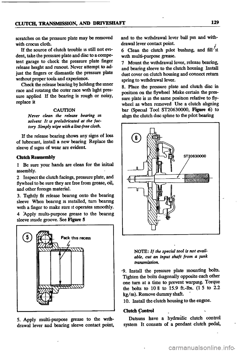
Use
a
clutch
alIgning
bar
Special
Tool
ST20630000
FIgDfe
6
to
alIgn
the
clutch
dISc
splIne
to
the
pllot
bearing
CD
NOTE
If
the
special
tool
is
not
avail
able
cut
an
input
shaft
from
a
Junk
transmission
9
Install
the
pressure
plate
mounting
bolts
Tighten
the
bolts
dIagonally
opposite
each
other
one
turn
at
a
time
to
prevent
warpmg
Torque
the
bolts
to
10
8
to
15
9
ft
lbs
1
5
to
2
2
kg
m
Remove
durmny
shaft
10
Install
the
clutch
housing
to
the
engme
Clutch
ntrol
Datsuns
have
a
hydraulic
clutch
control
system
It
consISts
of
a
pendant
clutch
pedal
Page 135 of 252

130
CHAPTER
ELEVEN
master
cylInder
operatlng
cylinder
and
with
drawal
lever
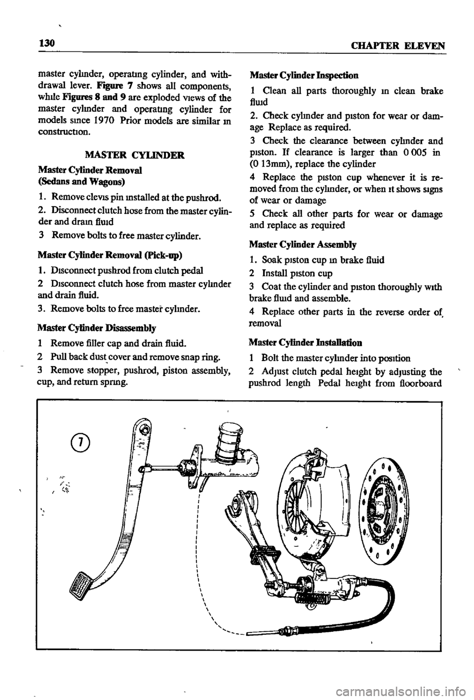
Figure
7
shows
all
components
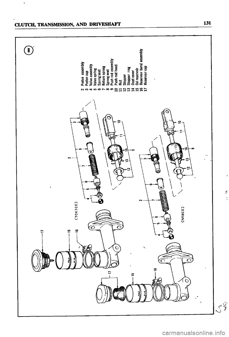
whlle
Figures
8
and
9
are
exploded
VIews
of
the
master
cylmder
and
operatIng
cylinder
for
models
smce
1970
Prior
models
are
similar
In
construction
MASTER
CYLINDER
Master
Cylinder
Removal
Sedans
and
Wagons
1
Remove
cleVIS
pin
mstalled
at
the
pushrod
2
Disconnect
clutch
hose
from
the
master
cylin
der
and
dram
flwd
3
Remove
bolts
to
free
master
cylinder
Master
Cylinder
Removal
Pick
up
1
DIsconnect
pushrod
from
clutch
pedal
2
DIsconnect
clutch
hose
from
master
cylInder
and
drain
fluid
3
Remove
bolts
to
free
master
cylInder
Master
Cylinder
Disassembly
1
Remove
filler
cap
and
drain
fluid
2
Pull
back
dust
cover
and
remove
snap
ring
3
Remove
stopper
pushrod
piston
assembly
cup
and
return
spnng
CD
i
Master
Cylinder
Inspection
1
Clean
all
parts
thoroughly
In
clean
brake
flwd
2
Check
cylInder
and
pISton
for
wear
or
dam
age
Replace
as
required
3
Check
the
clearance
between
cylInder
and
pIston
If
clearance
is
larger
than
0
005
in
0
13mm
replace
the
cylinder
4
Replace
the
pISton
cup
whenever
it
is
re
moved
from
the
cylInder
or
when
It
shows
SIgnS
of
wear
or
damage
5
Check
all
other
parts
for
wear
or
damage
and
replace
as
required
Master
Cylinder
Assembly
1
Soak
piston
cup
m
brake
fluid
2
Install
pIston
cup
3
Coat
the
cylinder
and
pIston
thoroughly
WIth
brake
flwd
and
assemble
4
Replace
other
parts
in
the
reverse
order
of
removal
Master
Cylinder
Installation
1
Bolt
the
master
cylInder
into
pOSItion
2
Adjust
clutch
pedal
heIght
by
adjusting
the
pushrod
length
Pedal
heIght
from
floorboard
Page 136 of 252
e
j
11
i
Il
Il
15
2
Tl
CTOKICO
2
Piston
assembly
3
Piston
cup
4
Valve
assembly
CI
5
Val
e
spring
I
6
Spnng
seat
7
Return
spring
8
Spnng
seat
9
Push
rod
assembly
10
Push
rod
head
11
Nut
12
Stopper
13
Stopper
ring
14
Dust
cover
15
0
reservoir
2
rl
16
Reservoir
bend
assembly
17
ReservOir
cap
NABCO
1
k
IN