Page 97 of 252

91
CHAPTER
NINE
bon
the
serIes
coll
demagnetizes
agatnst
the
shunt
cOIl
The
return
spnng
causes
the
plunger
to
return
to
the
origmal
posItIon
stoppmg
the
starter
The
overrunnmg
clutch
provIdes
for
positIve
meshmg
and
unmeshmg
of
the
pmlOn
gear
and
flywheerrmg
gear
and
perinitStlie
pmlon
to
overrun
the
armature
after
the
engme
has
started
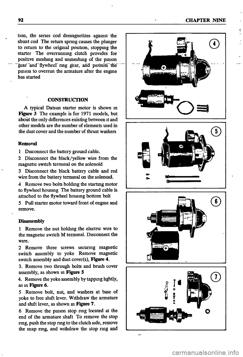
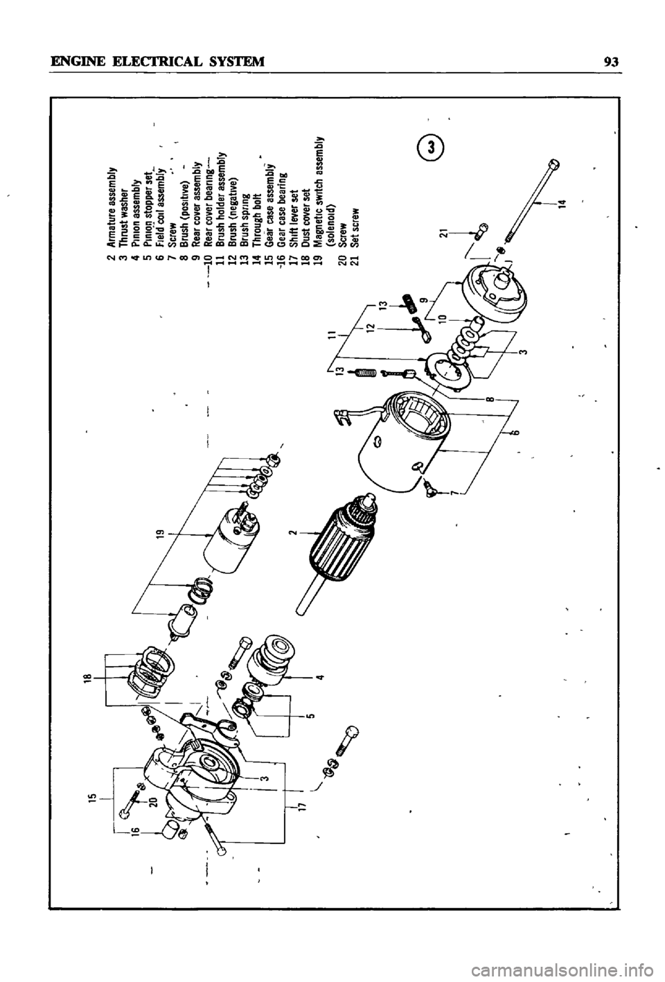
CONSTRUCIlON
A
typical
Datsun
starter
motor
is
shown
m
Figure
3
The
example
is
for
1971
models
but
about
the
only
dIfferences
existing
between
It
and
other
models
are
the
number
of
elements
used
in
the
dust
cover
and
the
number
of
thrust
washers
Removal
1
DIsconnect
the
battery
ground
cable
2
Disconnect
the
black
yellow
wire
from
the
magnetIc
sWitch
tennmal
on
the
solenoid
3
Disconnect
the
black
battery
cable
and
red
wire
from
the
battery
tennmal
on
the
solenOId
4
Remove
two
bolts
holdmg
the
startmg
motor
to
flywheel
hOUSIng
The
battery
ground
cable
is
attached
to
the
flywheel
hOUSIng
bottom
bolt
5
Pull
starter
motor
toward
front
of
engme
and
remove
Disassembly
1
Remove
the
nut
holdIng
the
electrIc
WIre
to
the
magnetIc
sWItch
M
tennmal
DIsconnect
the
WIre
2
Remove
three
screws
securmg
magnetic
switch
assembly
to
yoke
Remove
magnetic
sWItch
assembly
and
dust
cover
s
Figure
4
3
Remove
two
through
bolts
and
brush
cover
assembly
as
shown
m
Figure
5
4
Remove
the
yoke
assembly
by
tappmg
lIghtly
as
In
Figure
6
5
Remove
bolt
nut
and
washers
at
base
of
yoke
to
free
shut
lever
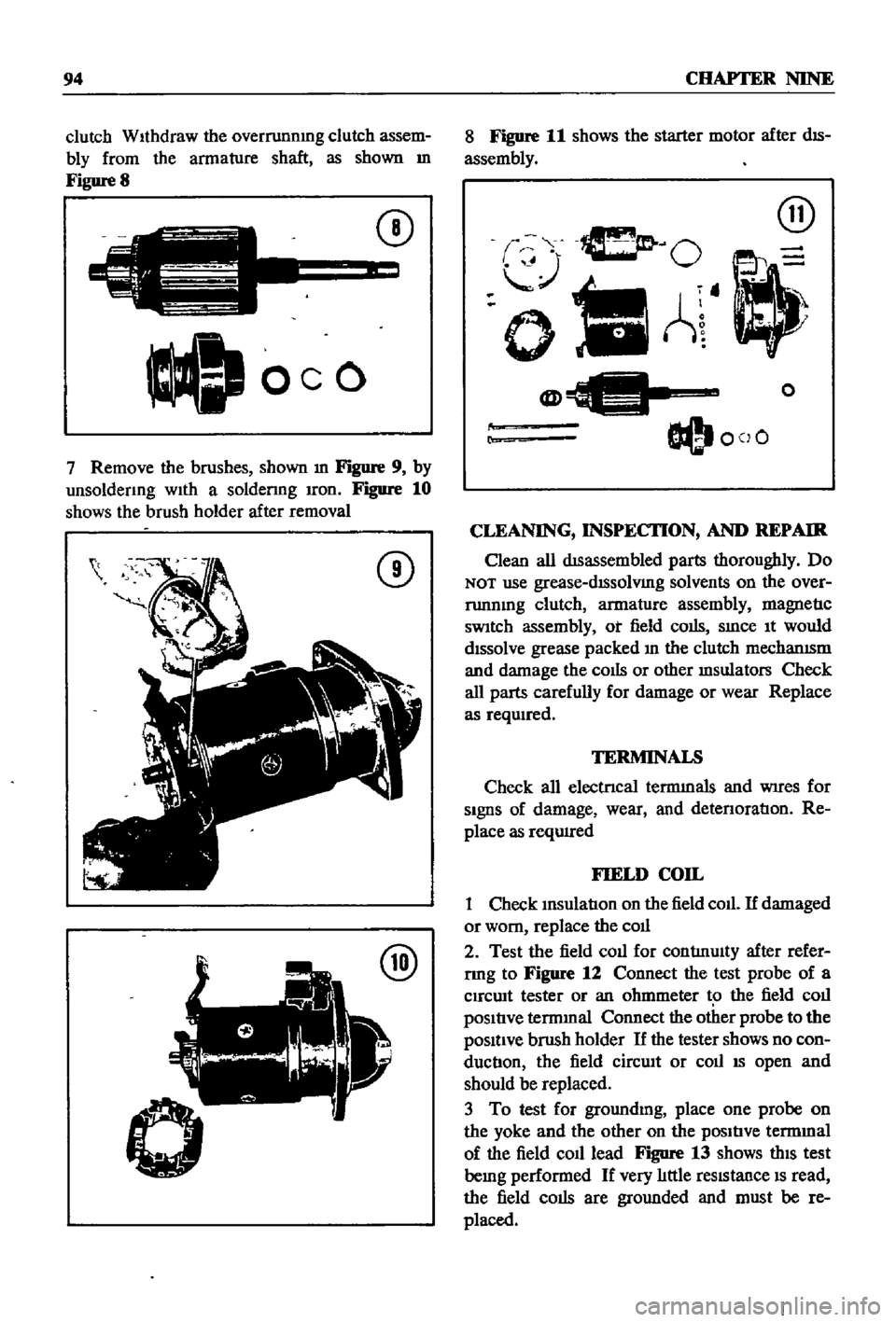
WIthdraw
the
armatlIre
and
shut
lever
as
shown
m
Figure
7
6
Remove
the
pInIOn
stop
nng
located
at
the
end
of
the
armature
shaft
To
remove
the
stop
nng
push
the
stop
nng
to
the
clutch
SIde
remove
the
snap
nng
and
Withdraw
the
stop
nng
and
CD
c
0
I
CD
Ml
ml
CD
a
I
II
0
l
g
I
o
Page 98 of 252
5
2
Armeture
assembly
3
thrust
washer
4
PinIon
assembly
5
PInion
stopper
set
6
fle
rCOJ1
assembly
7
Screw
8
Brush
positIVe
9
Reer
co
er
assembly
10
Rear
co
er
beerlng
11
Brush
holder
essembly
12
Brush
negatl
e
13
Brush
spnng
14
through
bolt
15
Gear
case
essembly
16
Gear
case
bearing
17
Shift
Iwer
set
18
Oust
cover
set
19
Magnetic
sWitch
assembly
solenoid
20
Screw
21
Set
screw
4
@
e
rl
14
i
i
j
Page 99 of 252

94
CHAPTER
NINE
clutch
WIthdraw
the
overrunnmg
clutch
assem
bly
from
the
armature
shaft
as
shown
m
Figure
8
C
J
oeo
CD
7
Remove
the
brushes
shown
m
Figure
9
by
unsoldenng
wIth
a
soldenng
Iron
Figure
10
shows
the
brush
holder
after
removal
CD
@
8
Figure
11
shows
the
starter
motor
after
dIS
assembly
@
O
oIlA
@
O@I
coO
o
r
CLEANING
INSPECI10N
AND
REPAIR
Clean
all
dISassembled
parts
thoroughly
Do
NOT
use
grease
dISsolVIng
solvents
on
the
over
runnmg
clutch
armature
assembly
magnetIc
sWItch
assembly
ot
field
colis
SInce
It
would
dIssolve
grease
packed
In
the
clutch
mechanISm
and
damage
the
cOIls
or
other
msulators
Check
all
parts
carefully
for
damage
or
wear
Replace
as
reqwred
TERMINALS
Check
all
electrIcal
termInals
and
WIres
for
SIgnS
of
damage
wear
and
detenoratIon
Re
place
as
reqUIred
FIELD
COIL
1
Check
InsulatIon
on
the
field
coll
If
damaged
or
worn
replace
the
coll
2
Test
the
field
coll
for
contlnulty
after
refer
rmg
to
Figure
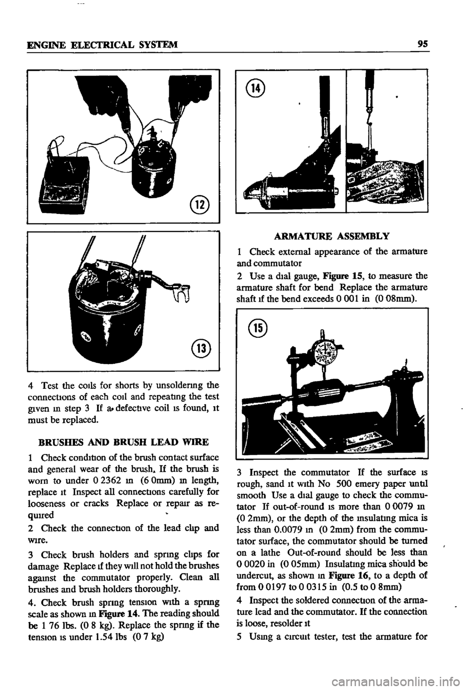
12
Connect
the
test
probe
of
a
Clrcwt
tester
or
an
ohmmeter
t
the
field
coll
pOSItIve
termInal
Connect
the
other
probe
to
the
pOSItIve
brush
holder
If
the
tester
shows
no
con
ductIon
the
field
cirCUIt
or
coll
IS
open
and
should
be
replaced
3
To
test
for
groundmg
place
one
probe
on
the
yoke
and
the
other
on
the
pOSItIve
termmal
of
the
field
co1l1ead
Figure
13
shows
thIS
test
bemg
performed
If
very
lIttle
reSIstance
IS
read
the
field
colis
are
grounded
and
must
be
re
placed
Page 100 of 252

ENGINE
ELECI
RlCAL
SYSTEM
9S
@
@
4
Test
the
COIls
for
shorts
by
unsoldermg
the
connectIons
of
each
coIl
and
repeatlng
the
test
given
m
step
3
If
a
defectIve
coil
IS
found
It
must
be
replaced
BRUSHES
AND
BRUSH
LEAD
WIRE
1
Check
condItIon
of
the
brush
contact
surface
and
general
wear
of
the
brush
If
the
brush
is
worn
to
under
02362
In
60mm
m
length
replace
It
Inspect
all
connectIons
carefully
for
looseness
or
cracks
Replace
or
reparr
as
re
qUIred
2
Check
the
connectIon
of
the
lead
clIp
and
WIre
3
Check
brush
holders
and
sprmg
clIps
for
damage
Replace
1f
they
will
not
hold
the
brushes
agaInst
the
commutator
properly
Clean
all
brushes
aIld
brush
holders
thoroughly
4
Check
brush
sprmg
tenSIon
WIth
a
spnng
scale
as
shown
m
Figure
14
The
reading
should
be
1
76
Ibs
0
8
kg
Replace
the
spnng
if
the
tenSIon
IS
under
1
54
Ibs
0
7
kg
@
ARMATURE
ASSEMBLY
1
Check
external
appearance
of
the
armature
and
commutator
2
Use
a
dIal
gauge
Figure
15
to
measure
the
armature
shaft
for
bend
Replace
the
armature
shaft
1f
the
bend
exceeds
0
001
in
0
08mm
@
3
Inspect
the
commutator
If
the
surface
IS
rough
sand
It
With
No
500
emery
paper
untIl
smooth
Use
a
dIal
gauge
to
check
the
commu
tator
If
out
of
round
IS
more
than
00079
In
0
2mm
or
the
depth
of
the
Insulatlng
mica
is
less
than
0
0079
In
0
2mm
from
the
commu
tator
surface
the
commutator
should
be
turned
on
a
lathe
Out
of
round
should
be
less
than
o
0020
in
0
05mm
Insulatmg
mica
should
be
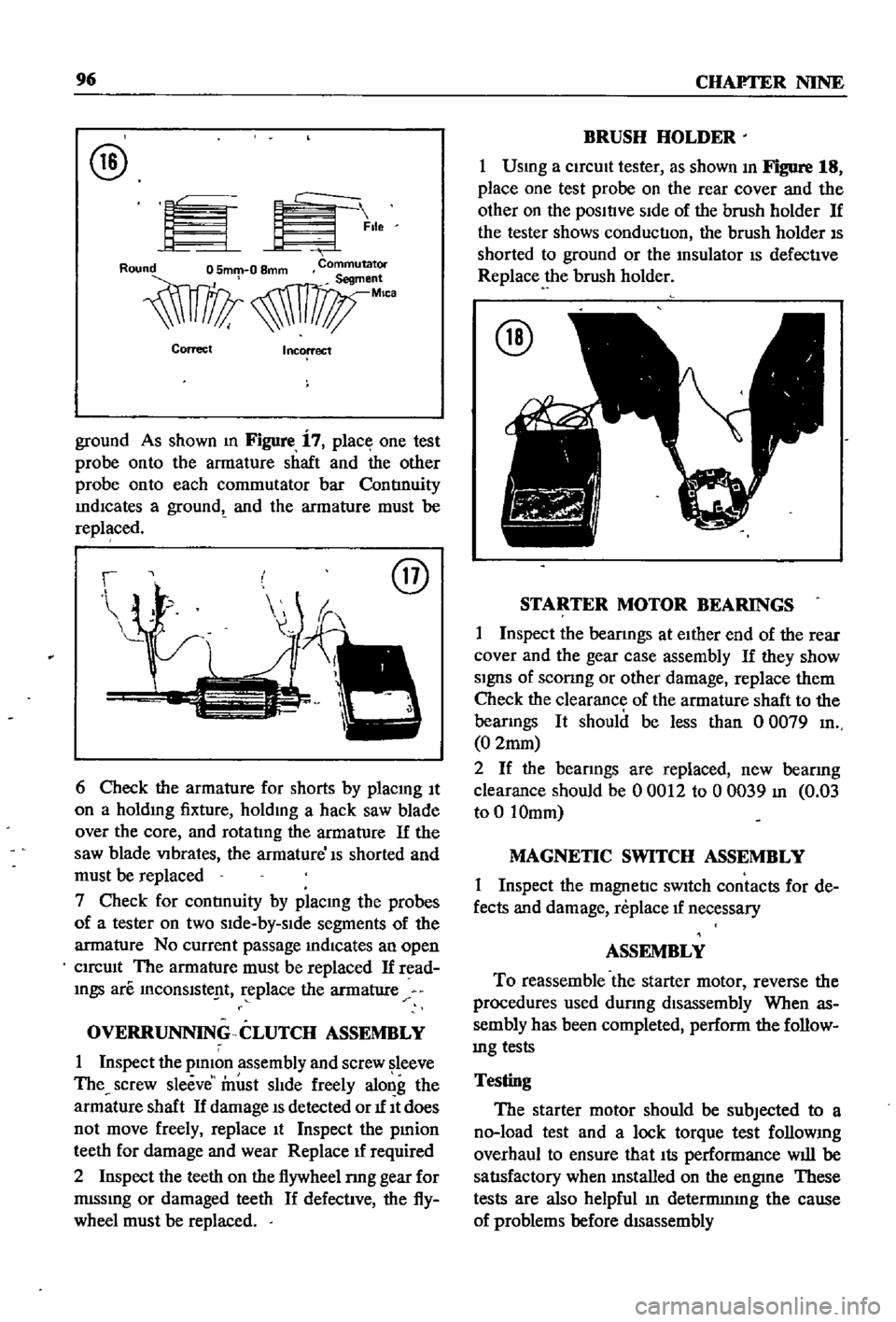
undercut
as
shown
m
Figure
16
to
a
depth
of
from
0
0197
to
0
0315
in
0
5
to
0
8mm
4
Inspect
the
soldered
connectIon
of
the
arma
ture
lead
and
the
commutator
If
the
connection
is
loose
resolder
It
5
Usmg
a
clrcmt
tester
test
the
armature
for
Page 101 of 252

96
CHAFTER
NINE
@
EK
lle
Correct
Incorrect
ground
As
shown
m
Figure
i
7
place
one
test
probe
onto
the
armature
shaft
and
the
other
probe
onto
each
commutator
bar
ContInuity
IndICates
a
groundt
and
the
armature
must
be
replaced
@
6
Check
the
armature
for
shorts
by
placmg
It
on
a
holdmg
fixture
holdmg
a
hack
saw
blade
over
the
core
and
rotatIng
the
armature
If
the
saw
blade
VIbrates
the
armature
Is
shorted
and
must
be
replaced
7
Check
for
contInuity
by
placmg
the
probes
of
a
tester
on
two
sIde
by
slde
segments
of
the
armature
No
current
passage
mdlcates
an
open
CIrcUIt
The
armature
must
be
replaced
If
read
mgs
are
InCOnslste
t
replace
the
armature
OVERRUNNING
CLUTCH
ASSEMBLY
1
Inspect
the
plmon
assembly
and
screw
leeve
The
screw
sleeve
must
slIde
freely
along
the
armature
shaft
If
damage
IS
detected
or
1f
It
does
not
move
freely
replace
It
Inspect
the
pmion
teeth
for
damage
and
wear
Replace
1f
required
2
Inspect
the
teeth
on
the
flywheel
nng
gear
for
mlssmg
or
damaged
teeth
If
defective
the
fly
wheel
must
be
replaced
BRUSH
HOLDER
1
Usmg
a
CirCUIt
tester
as
shown
In
Figure
18
place
one
test
probe
on
the
rear
cover
and
the
other
on
the
posltlve
SIde
of
the
brush
holder
If
the
tester
shows
conduction
the
brush
holder
IS
shorted
to
ground
or
the
msulator
IS
defective
Replace
the
brush
holder
@
STARTER
MOTOR
BEARINGS
1
Inspect
the
bearmgs
at
eIther
end
of
the
rear
cover
and
the
gear
case
assembly
If
they
show
SignS
of
sconng
or
other
damage
replace
them
Check
the
clearance
of
the
armature
shaft
to
the
bearmgs
It
should
be
less
than
0
0079
In
0
2mm
2
If
the
bearings
are
replaced
new
bearing
clearance
should
be
00012
to
00039
In
0
03
to
0
10mm
MAGNETIC
SWITCH
ASSEMBLY
1
Inspect
the
magnetic
sWItch
contacts
for
de
fects
and
damage
replace
1f
necessary
ASSEMBLY
To
reassemble
the
starter
motor
reverse
the
procedures
used
dUring
disassembly
When
as
sembly
has
been
completed
perform
the
follow
mg
tests
Testing
The
starter
motor
should
be
subjected
to
a
no
load
test
and
a
lock
torque
test
follOWIng
overhaul
to
ensure
that
Its
performance
will
be
satIsfactory
when
mstalled
on
the
engme
These
tests
are
also
helpful
In
detennmIng
the
cause
of
problems
before
dIsassembly
Page 102 of 252

ENGINE
ELECI
RlCAL
SYSTEM
97
No
Load
Lock
Torque
Test
1
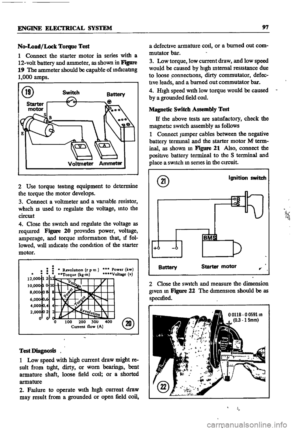
Connect
the
starter
motor
in
series
with
a
12
volt
battery
and
antmeter
as
shown
in
Figure
19
The
antmeter
should
be
capable
of
mdIcatIng
1
000
amps
@
Switch
Voltmeter
Ammeter
2
Use
torque
testlng
equipment
to
determine
the
torque
the
motor
develops
3
Connect
a
voltmeter
and
a
vanable
resistor
WhICh
IS
used
to
regulate
the
voltage
Into
the
circwt
4
Close
the
sWitch
and
regulate
the
voltage
as
reqUIred
Figure
20
proVIdes
power
voltage
amperage
and
torque
mformatIon
that
1f
fol
lowed
will
mdIcate
the
condItion
of
the
starter
motor
Power
kw
Voltage
v
@
Test
Diagnosis
1
Low
speed
with
high
current
draw
might
re
sult
from
tIght
dirty
or
worn
bearings
bent
armatlIre
shaft
loose
field
call
or
a
shorted
armatlIre
2
Fatlure
to
operate
With
htgh
current
draw
may
result
from
a
gromlded
or
open
field
coil
a
defectIve
armature
coll
or
a
burned
out
com
mutator
bar
3
Low
torque
low
current
draw
and
low
speed
would
be
caused
by
hIgh
Internal
reSIStance
due
to
loose
connectIons
dirty
commutator
defec
tIve
leads
and
a
burned
out
commutator
bar
4
HIgh
speed
With
low
torque
would
be
caused
by
a
grounded
field
coll
Magnetic
Switch
Assembly
Test
H
the
above
tests
are
satIsfactory
check
the
magnetIc
SWitch
assembly
as
follows
1
Connect
Jumper
cables
between
the
negative
battery
tennmal
and
the
starter
motor
M
term
inal
as
shown
In
Figure
21
Also
connect
the
positIve
battery
terminal
to
the
S
terminal
and
place
a
SWitch
m
senes
in
the
CIrCuit
@
Ignition
switch
9
I
i
j
Battery
Starter
motor
rr
2
Close
the
SWitch
and
measure
the
dimension
given
m
Figure
22
The
dimensIon
should
be
as
specIfied
o
0591m
15mm
Page 103 of 252

98
CHAPTER
NINE
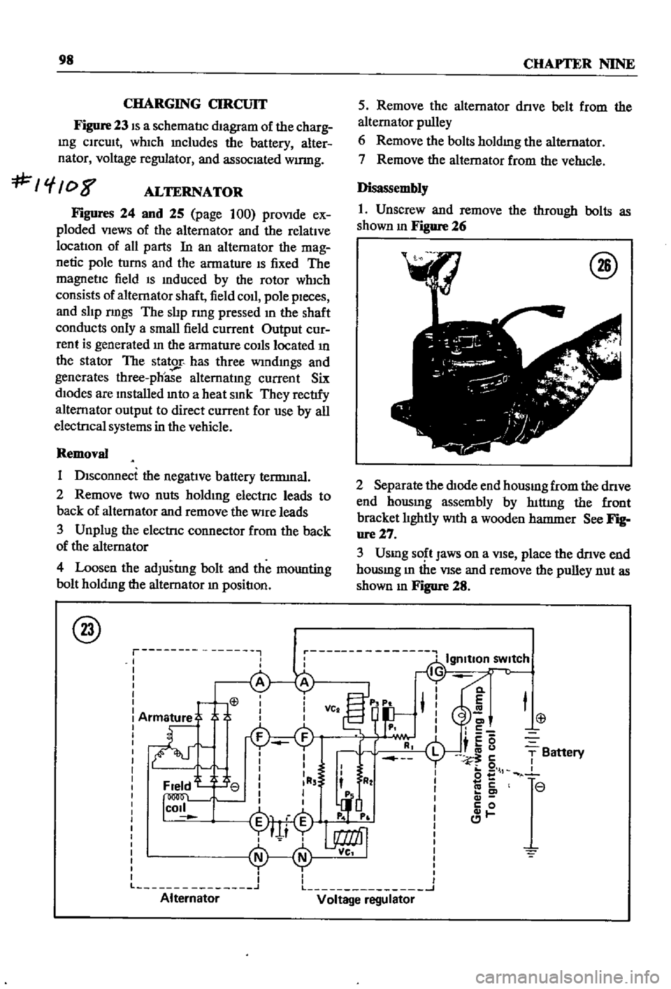
CHARGING
CIRCUIT
Figure
23
IS
a
schematIc
dIagram
of
the
charg
Ing
CIrcuIt
whIch
mcludes
the
battery
alter
nator
voltage
regulator
and
assocIated
wumg
f
08
ALTERNATOR
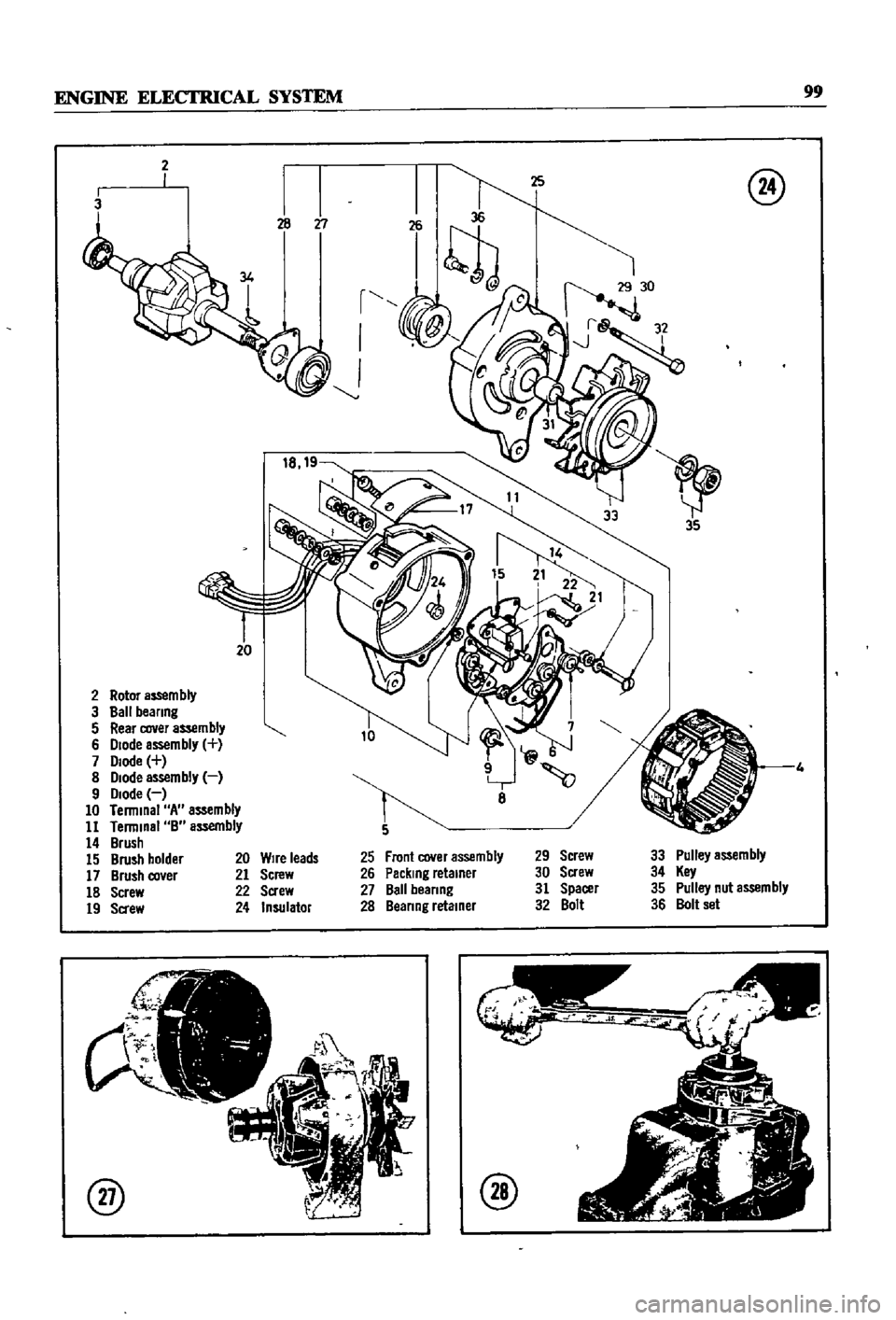
Figures
24
and
25
page
100
proVIde
ex
ploded
VIews
of
the
alternator
and
the
relatIve
locatIon
of
all
parts
In
an
alternator
the
mag
netic
pole
turns
and
the
armature
IS
fixed
The
magnetIc
field
IS
Induced
by
the
rotor
wh1ch
consists
of
alternator
shaft
field
coIl
pole
pIeces
and
slIp
nngs
The
slIp
rmg
pressed
In
the
shaft
conducts
only
a
small
field
current
Output
cur
rent
is
generated
In
the
armature
COIls
located
In
the
stator
The
stator
has
three
wIndmgs
and
generates
three
phoase
alternatIng
current
Six
dIodes
are
Installed
mto
a
heat
SInk
They
rectIfy
alternator
output
to
direct
current
for
use
by
all
electrIcal
systems
in
the
vehicle
Removal
1
DIsconnect
the
negatIve
battery
terrmnal
2
Remove
two
nuts
holdIng
electnc
leads
to
back
of
alternator
and
remove
the
Wire
leads
3
Unplug
the
electrIc
connector
from
the
back
of
the
alternator
4
Loosen
the
adJustlng
bolt
and
the
mounting
bolt
holdIng
the
alternator
In
positIon
@
r
I
I
I
L
Alternator
5
Remove
the
alternator
dnve
belt
from
the
alternator
pulley
6
Remove
the
bolts
holdmg
the
alternator
7
Remove
the
alternator
from
the
veh1cle
Disassembly
1
Unscrew
and
remove
the
through
bolts
as
shown
m
Figure
26
@
2
Separate
the
dIOde
end
housmg
from
the
dnve
end
hOUSIng
assembly
by
hlttmg
the
front
bracket
lIghtly
WIth
a
wooden
hatnnler
See
Fig
ure27
3
Usmg
SO
t
Jaws
on
a
VIse
place
the
dnve
end
housmg
m
the
VIse
and
remove
the
pulley
nut
as
shown
m
Figure
28
Cl
E
C
c5
i
u
5
o
l
co
c
c
0
1
T
Battery
r
r
L
J
Voltage
regulator
Page 104 of 252
ENGINE
ELECfRlCAL
SYSTEM
99
2
3
r
I
J
20
2
Rotor
aS5em
bly
3
Ball
beanng
5
Rear
cover
assembly
6
Diode
assembly
7
Diode
8
Diode
assembly
9
Diode
10
Terminal
A
assembly
11
Terminal
B
assembly
14
Brush
15
Brush
holder
17
Brush
co
er
18
Screw
19
Sa
ew
@
8
Front
cover
assembly
Packing
retainer
Ball
beanng
Beanng
retainer
29
Screw
30
Screw
31
Spacer
32
Bolt
33
Pulley
assembly
34
Key
35
Pulley
nut
assembly
36
Bolt
set
20
Wire
leads
21
Screw
22
Screw
24
Insulator
@
@