Page 137 of 252
132
CHAPTER
ELEVEN
CD
NAnCO
22
20
21
r
i
T
l
C
r
Jl
i
i
18
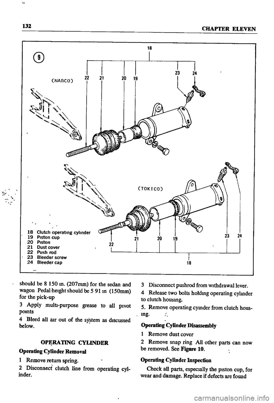
Clutch
operating
cylinder
19
Piston
cup
20
PIston
21
Dust
cover
22
Push
rod
23
Bleeder
screw
24
Bleeder
cap
22
I
should
be
8
150
m
207mm
for
the
sedan
and
wagon
Pedal
heIght
should
be
591
m
150mm
for
the
pick
up
3
Apply
multI
purpose
grease
to
all
PIvot
pOInts
4
Bleed
all
aIr
out
of
the
sy
tem
as
dIscussed
below
OPERATING
CYLINDER
Operating
CyHnder
Removal
1
Remove
retum
spring
2
Disconnect
clutch
line
from
operating
cyl
inder
18
Ii
TOKICO
21
I
LL
18
23
24
I
I
3
Disconnect
pushrod
from
wIthdrawal
lever
4
Release
two
bolts
holdmg
operating
cylInder
to
clutch
hOUSIng
5
Remove
operating
cymder
from
clutch
hous
mg
Operating
CyHnder
Disassembly
1
Remove
dust
cover
2
Remove
snap
ring
All
other
parts
can
now
be
removed
See
Figure
10
Operating
CyHnder
Inspection
Check
all
parts
especIally
the
pIston
cup
for
wear
and
damage
Replace
if
defects
are
found
Page 138 of 252

CLUTCH
TRANSMISSION
AND
DRlVESIIAFI
133
C
8
Q@J
@
C
Operating
Cylinder
Reassembly
1
Soak
pISton
cup
m
brake
flUid
and
Install
It
In
the
same
pOSitIOn
as
before
removal
2
Apply
brake
flUid
to
the
cylInder
and
pIston
before
mstalImg
piston
3
Replace
all
parts
m
the
reverse
order
of
removal
Operating
Cylinder
Installation
1
RemstallatIon
IS
the
reverse
of
removal
2
Bleed
aIr
from
the
hydraulIc
system
3
Adjust
the
pushrod
so
that
withdrawal
lever
end
play
IS
0
0787
to
0
1181
In
2
0
to
3
Omm
Procedures
for
the
adjustment
are
given
below
WITHDRAWAL
LEVER
AD
JUSTMENT
Correct
adjustment
of
the
clutch
withdrawal
lever
IS
essentIal
InsufficIent
free
travel
between
the
release
bearmg
and
dIaphragm
fingers
can
cause
the
clutch
to
slIp
ExceSSIve
free
travel
can
prevent
full
dISengagement
of
the
clutch
Refer
to
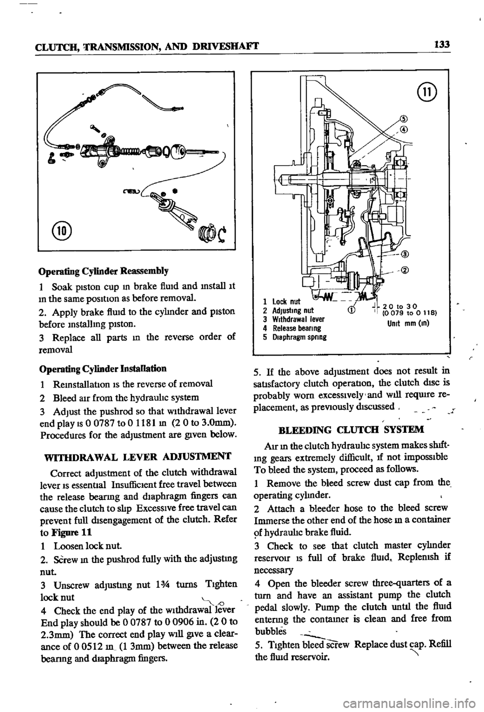
Figure
11
1
Loosen
lock
nut
2
SCrew
In
the
pushrod
fully
with
the
adjustmg
nut
3
Unscrew
adJustmg
nut
1
turns
TIghten
lock
nut
J
4
Check
the
end
play
of
the
wIthdrawal
lever
End
play
should
be
0
0787
to
0
0906
in
2
0
to
2
3mm
The
correct
end
play
will
give
a
clear
ance
of
0
0512
m
1
3mm
between
the
release
bearmg
and
diaphragm
fingers
@
1
Lock
nut
2
AdJustmg
nut
3
Wrthdrawal
ever
4
Release
beer
ng
5
Diaphragm
spnng
20
to
30
0
079
to
0
11
B
Unit
mm
m
5
If
the
above
adjustment
does
not
result
in
satIsfactory
clutch
operatIon
the
clutch
dISC
is
probably
worn
excessIvely
and
will
reqUire
re
placement
as
preVIously
dIScussed
BLEEDING
CLUTCH
SYSTEM
AIr
In
the
clutch
hydraulIc
system
makes
shIft
Ing
gears
extremely
difficult
1f
not
impOSSIble
To
bleed
the
system
proceed
as
follows
1
Remove
the
bleed
screw
dust
cap
from
the
operating
cylInder
2
Attach
a
bleeder
hose
to
the
bleed
screw
Immerse
the
other
end
of
the
hose
m
a
container
f
hydraulIc
brake
fluid
3
Check
to
see
that
clutch
master
cylInder
reservoir
IS
full
of
brake
flUid
ReplenISh
if
necessary
4
Open
the
bleeder
screw
three
quarters
of
a
tlIrn
and
have
an
assistant
pump
the
clutch
pedal
slowly
Pump
the
clutch
until
the
flUid
entenng
the
contatner
is
clean
and
free
from
bubbles
5
TIghten
bleed
screw
Replace
dust
cap
Refill
the
flUid
reservoir
Page 139 of 252

134
CHAPTER
ELEVEN
CLUTCH
SERVICE
DATA
AND
SPECIF1CATIONS
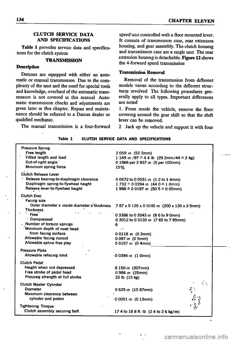
Table
1
proVIdes
serVIce
data
and
specifica
tIons
for
the
clutch
system
TRANSMISSION
Description
Datsuns
are
eqUIpped
with
either
an
auto
matic
or
manual
transrmSSIOn
Due
to
the
com
pleXity
of
the
unIt
and
the
need
for
special
tools
and
knowledge
overhaul
of
the
automatic
trans
mISSIon
is
not
covered
In
thIS
manual
Auto
matIc
transmISSIOn
checks
and
adjustments
are
given
later
m
thIS
chapter
Reparr
and
mainte
nance
should
be
referred
to
a
Datsun
dealer
or
qualIfied
mechamc
The
manual
transmission
is
a
four
forward
Table
1
speed
unlt
controlled
With
a
floor
mounted
lever
It
consIsts
of
transrmSSIOn
case
rear
extensIOn
housing
and
gear
assembly
The
clutch
housmg
and
transmissIOn
case
are
a
sIngle
unIt
The
rear
extension
housmg
is
detachable
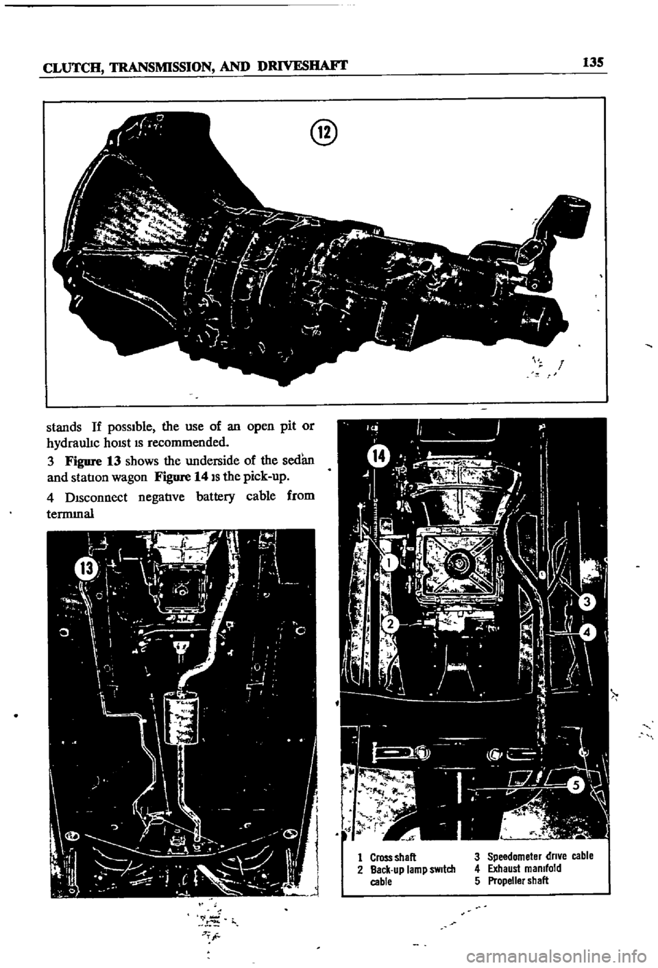
Figure
12
shows
the
4
forward
speed
transmission
Transmission
Removal
Removal
of
the
transmIssion
from
dIfferent
models
Varles
accordmg
to
the
dIfferent
struc
ture
Involved
The
following
procedures
gen
erally
apply
to
all
types
Important
dIfferences
are
noted
1
Prom
InsIde
the
vehicle
remove
the
floor
covenng
around
the
gear
shift
so
that
the
shIft
lever
can
be
removed
2
Jack
up
the
vehIcle
and
support
it
with
four
CLUTCH
SERVICE
DATA
AND
SPECIFICATIONS
Pressure
Spring
Free
length
Fitted
length
and
load
Out
of
rlght
angle
MInimum
sprmg
force
Clutch
Release
Lever
Release
bearlng
to
dlaphragm
clearance
Diaphragm
sprlng
to
flywheel
height
Release
lever
to
flywheel
height
Clutch
DISC
FaCing
size
Outer
dIameter
x
inSide
diameter
x
thlckness
Thickness
Free
Compressed
Number
of
tOrslO
1
springs
Minimum
depth
of
rivet
head
from
faCing
surface
Allowable
facmg
runout
Allowable
spline
free
play
Pressure
Plate
Allowable
refacmg
limit
Clutch
Pedal
Height
when
not
depressed
Free
stroke
of
pedal
head
Pressmg
strength
at
full
stroke
Clutch
Master
Cylinder
Diameter
MaXimum
clearance
between
cylinder
and
pIston
Tightening
Torque
Clutch
assembly
securing
bolt
2
059
In
52
3mm
1
149
In
197
4
4
Ib
29
2mm
44
2
kg
o
1968
per
3
937
In
5
per
100mm
15
00472
to
0
0551
In
1
2
to
1
4mm
1732
0
0394
m
44
O
1
Omm
1
988
0
0197
In
505
0
05mm
787
X
5
120
x
0
0140
In
200
x
130
x
3
5mm
o
3386
to
0
3543
m
8
6
to
9
Omm
03012
to
0
3130
m
765
to
7
95mm
6
00118
In
03mm
o
097
In
0
5mm
00157
m
04mm
o
0394
In
1
Omm
8
150
m
207mm
o
984
m
25mm
33
Ib
15
kg
0625
m
15
87mm
00051
m
0
13mm
J
i
r
174
to
188ft
Ib
24
to
2
6
kg
m
Page 140 of 252
CLUTCH
TRANSMISSION
AND
DRIVESIIAFI
135
stands
If
possible
the
use
of
an
open
pit
or
hydraulIc
hOISt
IS
recommended
3
Figure
13
shows
the
underside
of
the
sedan
and
statIon
wagon
Figure
14
IS
the
pick
up
4
DIsconnect
negatIve
battery
cable
from
termInal
r
j
7T
@
r
1
Cross
shall
2
Back
up
lamp
sWitch
cable
3
Speedometer
dn
e
cable
4
Exhaust
manifold
5
Propeller
shall
Page 141 of 252

136
CHAPTER
ELEVEN
5
DIsconnect
and
remove
starter
motor
from
flywheel
housmg
as
descnbe4
In
Chapter
NIne
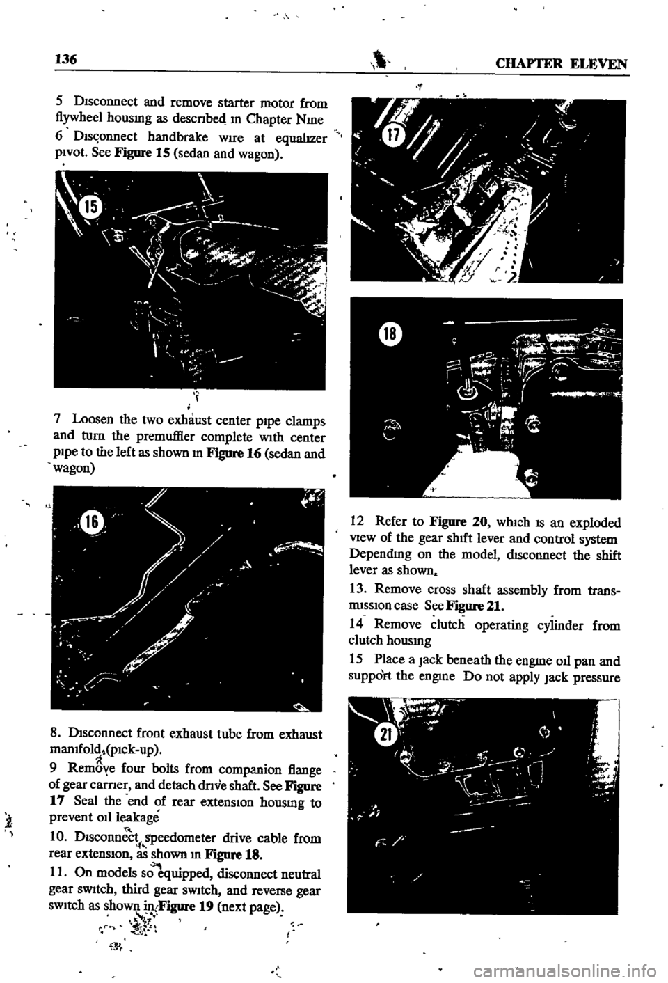
6
Dls
onnect
handbrake
WIre
at
equalIzer
pIVOt
See
Figure
15
sedan
and
wagon
I
j
7
Loosen
the
two
exhaust
center
p1pe
clamps
and
turn
the
premuffier
complete
With
center
pIpe
to
the
left
as
shown
m
FJgure
16
sedan
and
wagon
f
W
y
I
0
Y
h
0
ilo
8
DIsconnect
front
exhaust
tube
from
exhaust
man1fold
pICk
up
9
Rem
ye
four
bolts
from
companion
flange
of
gear
carner
and
detach
dnve
shaft
See
Figure
17
Seal
the
end
of
rear
extensIon
housmg
to
prevent
011
leakage
1
0
Dlsconn
i
gpeedometer
drive
cable
from
rear
extensIOn
as
shown
In
Figure
18
11
On
models
s
quipped
disconnect
neutral
gear
sWitch
third
gear
sWitch
and
reverse
gear
sWItch
as
shown
in
Figure
19
next
page
f
t
iT
l
t
t
W
12
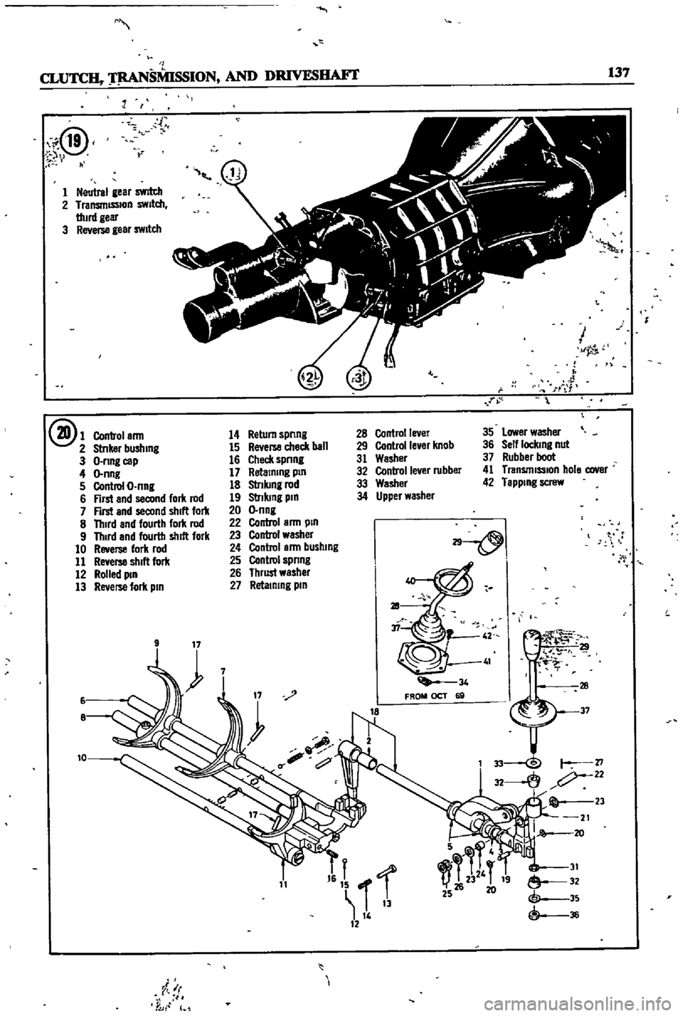
Refer
to
Figure
20
whIch
IS
an
exploded
View
of
the
gear
shIft
lever
and
control
system
DependIng
on
the
model
dISconnect
the
shift
lever
as
shown
13
Remove
cross
shaft
assembly
from
trans
rmsslOn
case
See
Figure
21
14
Remove
clutch
operating
cylinder
from
clutch
housmg
15
Place
a
Jack
beneath
the
engme
011
pan
and
SuppOFt
the
engme
Do
not
apply
Jack
pressure
Page 142 of 252
M
I
CL
SMISSION
AND
DRIVESIIAF1
137
i@
v
l
ll
r
1
Neutral
gear
swrtch
2
TransmISSIon
swllch
thud
geu
3
Reverse
gear
SWitch
@1
Control
arm
14
Return
spnng
2
StnkBr
bushmg
15
Re
erse
check
ball
3
O
nng
cep
16
Check
spnng
4
O
nng
17
Retalmng
pm
5
Control
O
nng
18
Slnlung
rod
6
First
and
second
fork
rod
19
Slnlung
pm
7
First
and
second
shill
fork
20
O
nng
8
Thud
and
fourth
lork
rod
22
Control
arm
pm
9
Third
and
fourth
shill
fork
23
Control
washer
10
Reverse
fork
rod
24
Control
arm
bushmg
11
Reverse
shill
fork
25
Control
spnng
12
Rolled
pm
26
Thrust
wesher
13
Reverse
fork
pm
27
Retammg
pm
9
0
11
f
Ir
foUr
1
i
1
k
jl
n
1
1
l
28
Control
lever
35
Lower
washer
29
Control
lever
knob
36
Self
lockmg
nut
31
Washer
37
Rubber
boot
32
Controlle
er
rubber
41
Tnmsmlsslon
hole
cover
33
Washer
42
Tappmg
screw
34
Upper
washer
29
c
28
37
16
t
f
f
1
I
13
1
12
5
T
2V
T
19
25
26
20
31
e
32
@
35
@
36
Page 143 of 252

138
CHAFfER
ELEVEN
to
dram
plug
Use
a
block
of
wood
between
the
011
pan
and
the
Jack
16
Remove
two
bolts
attaching
the
transmIS
sion
to
the
rear
engine
mount
Place
a
Jack
under
the
transmISSIon
and
support
the
transmissIOn
Remove
four
bolts
holdmg
the
rear
engme
cross
member
to
the
body
sedan
and
wagon
17
Place
a
Jack
under
the
transmISSIon
and
sup
port
the
transmISSIon
Remove
rear
engine
mount
from
transmlssiod
and
cross
member
as
shown
In
Figure
22
pIck
up
18
Lower
the
supporting
jacks
to
mclme
the
engine
downward
and
there
IS
sufficient
room
to
remove
the
transmission
19
Pull
the
transmission
towards
the
rear
until
the
dnve
shaft
splme
IS
clear
of
the
clutch
pres
sure
plate
Be
careful
not
to
damage
the
splines
or
the
pressure
plate
6
40
t
I
j
fI
1
2
fr
l
3332
3
1
TransmiSSion
case
2
TransmiSSion
case
3
Thread
taper
plug
t
4
TransmiSSion
Iront
cover
5
Front
cover
011
seal
6
Front
cover
gasket
7
fixmg
bolt
8
Flxmg
bolt
9
Spnng
washer
10
Rear
extension
11
Reer
extenSIon
011
seal
12
Breather
assembly
13
Extension
bushmg
14
Extension
gasket
15
Hex
bolt
16
Hex
bolt
17
Spllng
washer
18
Dowel
pm
19
Beallng
retainer
20
Hex
bolt
21
Spnng
washer
22
Bottom
cover
23
Bottom
cover
gasket
24
Bottom
cover
hex
bolt
25
Spnng
washer
26
Drem
plug
essembly
27
Dram
plug
assembly
29
SwItch
30
Hex
bolt
l
r
I
J
J
I
n
S
T
r
re
l
1
Rear
extension
mountmg
bolts
2
Rear
engme
mounting
bolts
20
Remove
the
transmISsion
by
lowenng
the
transmISsion
Jack
Transmission
Disassembly
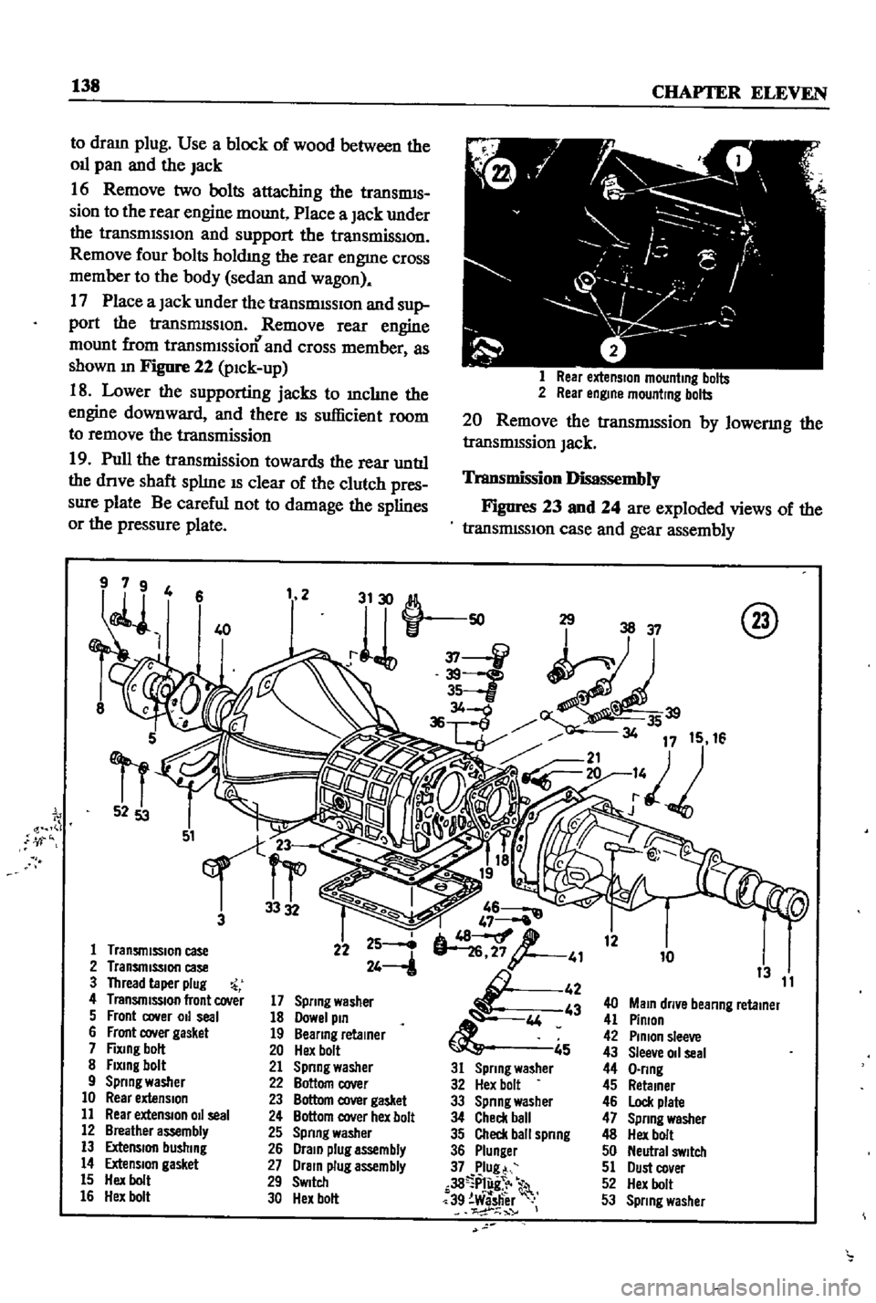
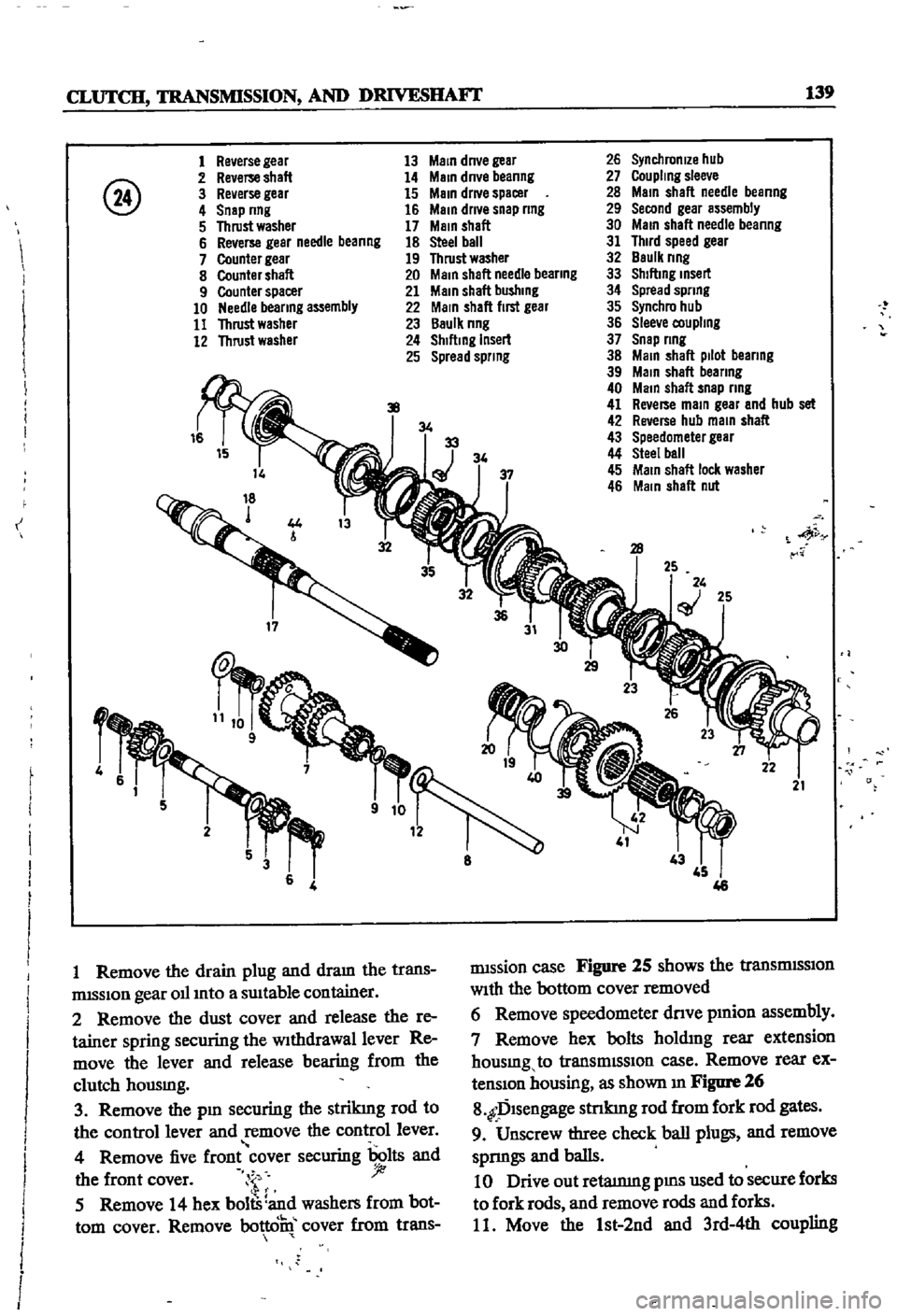
Figures
23
and
24
are
exploded
views
of
the
transrmSSlon
case
and
gear
assembly
@
46
47
6
i
4826J
1
41
44
5
31
Spring
washer
32
Hex
bolt
33
Spnng
washer
34
Check
ball
35
Check
ball
spnng
36
Plunier
37
Plug
r
38
P1
g
39
Washer
o
12
10
13
11
40
MaIO
dllve
beanng
retamer
41
Pinion
42
PInion
sleeve
43
Sleeve
011
seal
44
O
lIng
45
Retamer
46
Lock
plate
47
Spnng
washer
48
Hex
bolt
50
Neutral
SWitch
51
Dust
co
er
52
Hex
bolt
53
Sprmg
washer
Page 144 of 252

CLUTCH
TRANSMISSION
AND
DRIVESHAFI
139
@
1
Re
erse
gear
2
Re
erse
shaft
3
Reverse
gear
4
Snep
nng
5
Thrust
washer
6
Reverse
gear
needle
beanng
7
Counter
gear
8
Counter
shaft
9
Counter
spacer
10
Needle
bearing
assembly
11
Thrust
washer
12
Thrust
washer
J
f
I
I
I
I
I
I
I
I
I
I
J
I
I
i
I
f
4
rm
9
13
MaIO
dnve
gear
14
MaIO
dn
e
beanng
15
MaIO
drl
e
spacer
16
MelO
drl
e
snap
ring
17
MaIO
shaft
18
steel
ball
19
Thrust
washer
20
MaIO
shaft
needle
bearing
21
Meln
shaft
bushlOg
22
MaIO
shaft
flm
gear
23
Baulk
nng
24
Sh
ftlOg
Insert
25
Spread
sprlOg
9
1
Remove
the
drain
plug
and
dram
the
trans
rmSSlon
gear
011
Into
a
SUItable
container
2
Remove
the
dust
cover
and
release
the
re
tainer
spring
securing
the
Withdrawal
lever
Re
move
the
lever
and
release
bearing
from
the
clutch
housmg
3
Remove
the
pIn
securing
the
strikmg
rod
to
the
control
lever
and
remove
the
control
lever
4
Remove
five
front
cover
securing
bolts
and
the
front
cover
i
j
5
Remove
14
hex
bolts
and
washers
from
bot
tom
cover
Remove
bottcifu
cover
from
trans
I
I
I
I
I
I
i
i
J
34
34
26
Synchronize
hub
27
CoupllOg
slee
e
28
MaIO
shaft
needle
beanng
29
Second
gear
assembly
30
MaIO
shaft
needle
beanng
31
Third
speed
gear
32
Baulk
nng
33
ShlftlOg
IOsert
34
Spread
spring
35
Synchro
hub
36
Slee
e
coupllOg
37
Snep
nng
38
MaIO
shaft
pilot
beanng
39
Main
shaft
bearing
40
MaIO
shaft
snap
ring
41
Re
erse
maIO
gear
and
hub
set
42
Rwerse
hub
maIO
shaft
43
Speedometer
gear
44
Steel
ball
45
MaIO
sheft
loc
l
washer
46
MaIO
shaft
nut
28
iy
25
25
21
rmssion
case
Figure
25
shows
the
tranSmISSIon
With
the
bottom
cover
removed
6
Remove
speedometer
dnve
pmion
assembly
7
Remove
hex
bolts
holdmg
rear
extension
housmg
to
transmISSIon
case
Remove
rear
ex
tenSIon
housing
as
shown
m
Figure
26
8
fDlsengage
stnkmg
rod
from
fork
rod
gates
9
Unscrew
three
check
ball
plugs
and
remove
sprmgs
and
balls
10
Drive
out
retatnmg
pms
used
to
secure
forks
to
fork
rods
and
remove
rods
and
forks
11
Move
the
1st
2nd
and
3rd
4th
coupling