Page 57 of 252
52
CHAPTER
SIX
@
1oI
DlA
IlIA
AU
Al
I
2
1I
a
1I
1
6
L
us
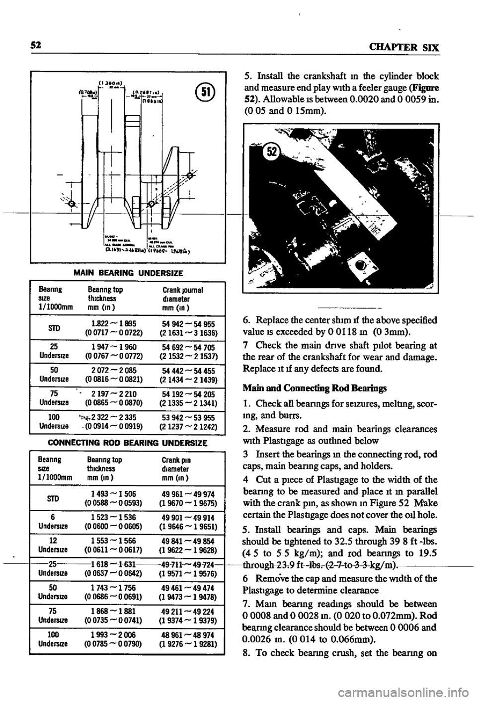
MAIN
BEARING
UNDERSIZE
Beanng
Beanng
top
Crank
Journal
sIZe
thickness
diameter
1
I000mm
mm
In
mm
In
STD
1
822
les5
54
942
54
955
0
0717
0
0722
2
1631
3
1636
25
1947
1960
54
692
54
705
Undersize
0
0767
0
0772
2
1532
2
1537
50
2072
2085
54
442
54
455
UndersIZe
00816
0
0821
2
1434
2
1439
75
2197
2
210
54
192
54
205
UndersIZe
0
0865
0
0870
2
1335
2
1341
100
2
322
2
335
53
942
53
955
UndersIZe
00914
0
0919
2
1237
2
1242
CONNECTING
ROD
BEARING
UNDERSIZE
Beanng
Beanng
top
Crank
pin
SIZe
thickness
diameter
l
loo0mm
mm
In
mm
In
STD
1493
1506
49961
49
974
0
0588
0
0593
1
9670
1
9675
6
1523
1536
49901
49
914
Undersize
0
0600
0
0605
1
9646
1
9651
12
1553
1566
49841
49
854
UndersIZe
00611
0
0617
1
9622
1
9628
25
1
618
1
631
49
711
49
724
UndersJZ8
0
0637
0
0642
1
9571
1
9576
50
1743
1756
49461
49
474
UndersIZe
00686
00691
1
9473
1
9478
75
1868
1881
49
211
49
224
UndelSlZ8
00735
0
0741
1
9374
1
9379
100
1993
2006
48
961
48
974
UndersIZe
0
0785
0
0790
1
9276
1
9281
5
Install
the
crankshaft
m
the
cylinder
block
and
measure
end
play
WIth
a
feeler
gauge
Figure
52
Allowable
IS
between
0
0020
and
0
0059
in
005
and
0
15mm
6
Replace
the
center
shIm
If
the
above
specified
value
IS
exceeded
by
0
0118
m
0
3mm
7
Check
the
main
dnve
shaft
puot
bearing
at
the
rear
of
the
crankshaft
for
wear
and
damage
Replace
It
If
any
defects
are
found
Main
and
Connecting
Rod
Bearings
1
Check
all
beanngs
for
seIZUres
meltIng
scor
mg
and
burrs
2
Measure
rod
and
main
bearings
clearances
WIth
PlastIgage
as
outhned
below
3
Insert
the
bearings
m
the
connecting
rod
rod
caps
main
beanng
caps
and
holders
4
Cut
a
pIece
of
PlastIgage
to
the
width
of
the
beanng
to
be
measured
and
place
It
m
parallel
with
the
crank
pm
as
shown
10
Figure
52
Make
certain
the
PlastIgage
does
not
cover
the
ou
hole
5
Install
bearings
and
caps
Main
bearings
should
be
tIghtened
to
32
5
through
398ft
lbs
45
to
55
kg
m
and
rod
beanngs
to
19
5
through
23
9
ft
lbs
2
7
to
3
3
kg
m
6
Remove
the
cap
and
measure
the
WIdth
of
the
PlastIgage
to
determine
clearance
7
Mam
beanng
readIngs
should
be
between
o
0008
and
0
0028
m
0
020
to
O
072mm
Rod
beanng
clearance
should
be
between
0
0006
and
0
0026
m
0014
to
0
066mm
8
To
check
beanng
crush
set
the
beanng
on
Page 58 of 252
ENGINE
53
the
mam
beanng
cap
and
the
cyhnder
block
beanng
recess
and
tighten
the
cap
bolts
to
the
proper
torque
WIth
a
torque
wrench
Tig
temng
torque
Main
bearings
506
to
57
8
It
Ib
70to80kg
m
195
to
23
9
It
Ib
27
to3
3
kg
m
Rod
beanngs
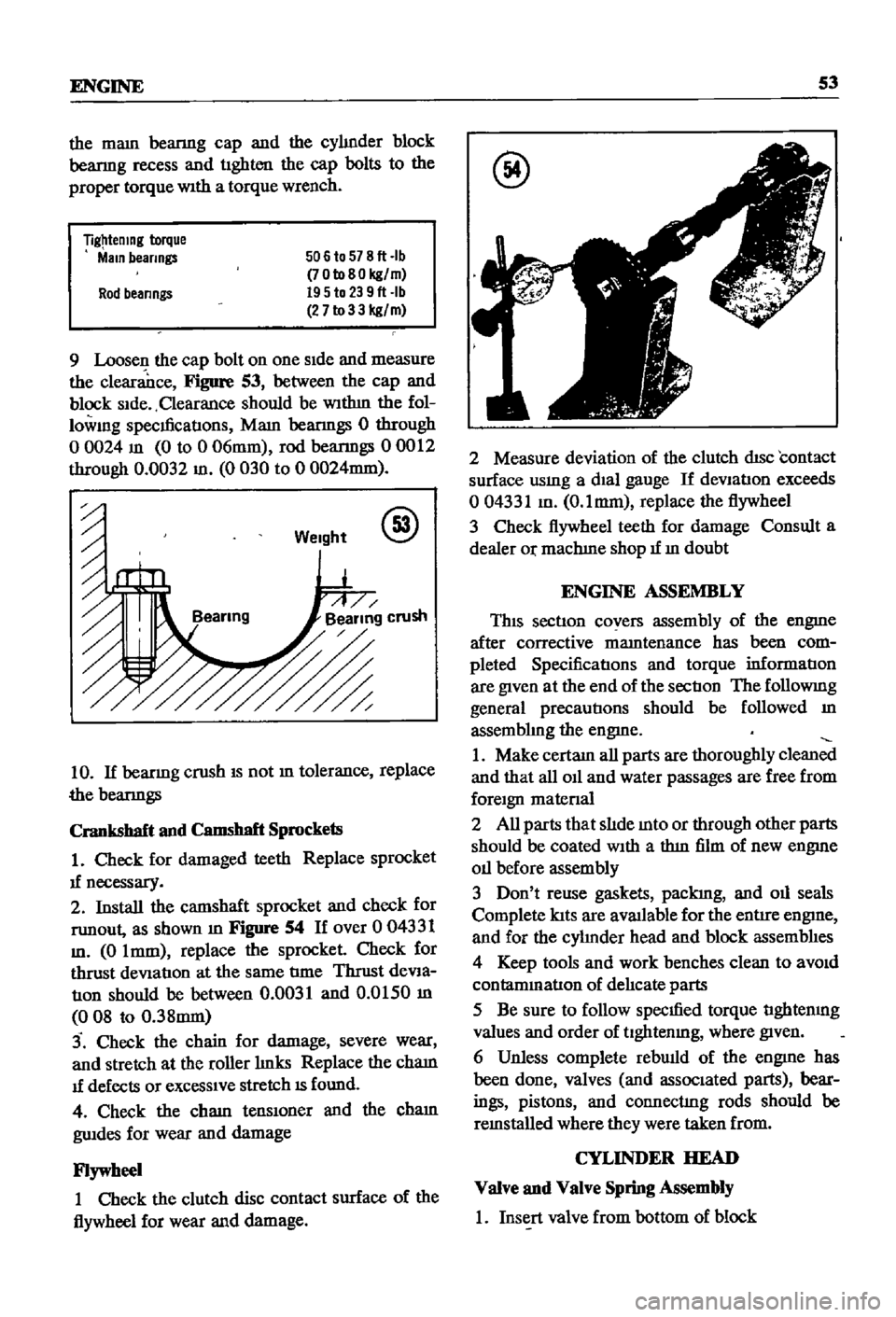
9
Loosen
the
cap
bolt
on
one
Side
and
measure
the
clearance
Figure
53
between
the
cap
and
block
Side
Clearance
should
be
WIthm
the
fol
lowmg
specmcatIons
Mam
beanngs
0
through
o
0024
m
0
to
0
06mm
rod
beanngs
00012
through
0
0032
m
0
030
to
0
0024mm
Weight
@
10
If
beanng
crush
IS
not
m
tolerance
replace
the
beanngs
Crankshaft
and
Camshaft
Sprockets
1
Check
for
damaged
teeth
Replace
sprocket
1f
necessary
2
Install
the
camshaft
sprocket
and
check
for
runout
as
shown
m
Figure
54
If
over
0
04331
m
0
Imm
replace
the
sprocket
Check
for
thrust
deViation
at
the
same
tIme
Thrust
deVia
tIOn
should
be
between
0
0031
and
0
0150
m
008
to
0
38mm
3
Check
the
chain
for
damage
severe
wear
and
stretch
at
the
roller
hnks
Replace
the
cham
1f
defects
or
exceSSIve
stretch
IS
found
4
Check
the
cham
tenslOner
and
the
cham
gwdes
for
wear
and
damage
Flywheel
1
Check
the
clutch
disc
contact
surface
of
the
flywheel
for
wear
and
damage
@
2
Measure
deviation
of
the
clutch
disc
contact
surface
usmg
a
dial
gauge
If
deVIation
exceeds
004331
m
O
lmm
replace
the
flywheel
3
Check
flywheel
teeth
for
damage
Consult
a
dealer
Or
machIne
shop
1f
m
doubt
ENGINE
ASSEMBLY
This
section
covers
assembly
of
the
engme
after
corrective
mamtenance
has
been
com
pleted
SpecificatIons
and
torque
informatIon
are
given
at
the
end
of
the
sectIon
The
followmg
general
precautions
should
be
followed
m
assembhng
the
engme
1
Make
certam
all
parts
are
thoroughly
clean
and
that
all
011
and
water
passages
are
free
from
foreign
matenal
2
All
parts
that
slIde
mto
or
through
other
parts
should
be
coated
With
a
thm
film
of
new
engme
011
before
assembly
3
Don
t
reuse
gaskets
packIng
and
011
seals
Complete
lats
are
aVlUlable
for
the
entire
engme
and
for
the
cyhnder
head
and
block
assemblIes
4
Keep
tools
and
work
benches
clean
to
aVOid
contammatlon
of
delIcate
parts
5
Be
sure
to
follow
specmed
torque
tIghtenmg
values
and
order
of
tlghtenmg
where
given
6
Unless
complete
rebwld
of
the
engme
has
been
done
valves
and
associated
parts
bear
ings
pistons
and
connectIng
rods
should
be
remstalled
where
they
were
taken
from
CYLINDER
HEAD
Valve
and
Valve
Spring
Assembly
1
Insert
valve
from
bottom
of
block
Page 59 of 252
54
CHAP1ER
SIX
2
Set
the
valve
spnng
seat
m
position
on
the
top
of
the
block
and
over
the
valve
stem
3
Place
the
oil
seal
over
the
valve
stem
4
Place
the
mner
and
outer
valve
spnngs
over
the
valve
stem
S
Place
the
spnng
retamer
over
the
springs
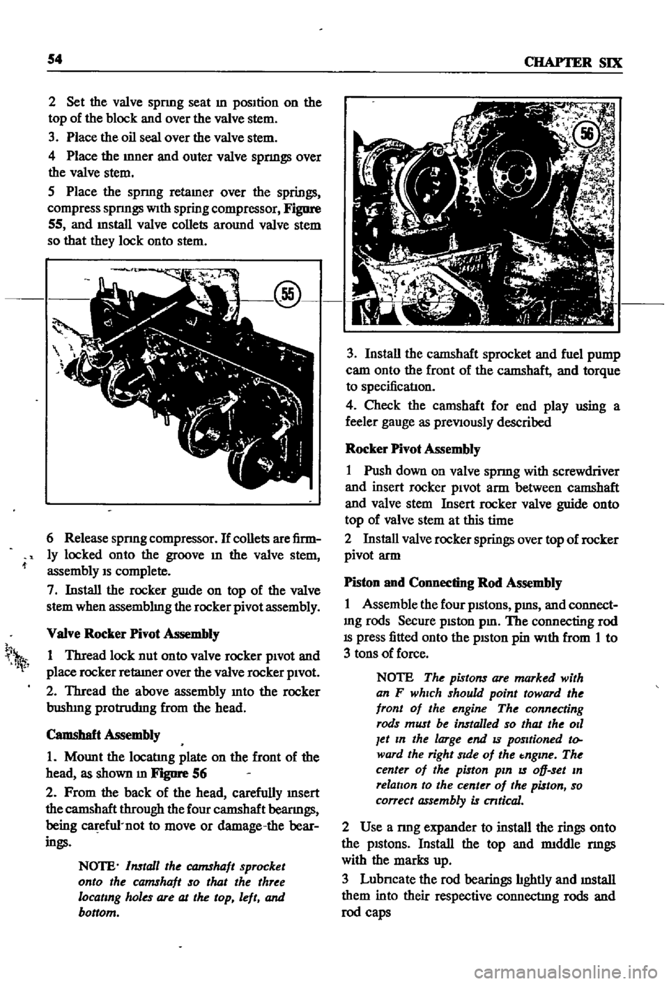
compress
spnngs
With
spring
compressor
Figure
55
and
mstall
valve
collets
around
valve
stem
so
that
they
lock
onto
stem
6
Release
spnng
compressor
If
collets
are
firm
ly
locked
onto
the
groove
m
the
valve
stem
assembly
IS
complete
7
Install
the
rocker
guIde
on
top
of
the
valve
stem
when
assemblmg
the
rocker
pivot
assembly
VaIve
Rocker
Pivot
Assembly
1
Thread
lock
nut
onto
valve
rocker
pivOt
and
place
rocker
retaIner
over
the
valve
rocker
pivOt
2
Thread
the
above
assembly
mto
the
rocker
bushIng
protrudIng
from
the
head
Camshaft
Assembly
1
Mount
the
locatIng
plate
on
the
front
of
the
head
as
shown
m
FJgIlI
1
56
2
From
the
back
of
the
head
carefully
InSert
the
camshaft
through
the
four
camshaft
beanngs
being
ca
efu1
not
to
move
or
damage
the
bear
ings
NOTE
Install
the
CQJ7IShaft
sprocket
onto
the
camshaft
so
that
the
three
locating
holes
are
at
the
top
left
and
bottom
h
1
3
Install
the
camshaft
sprocket
and
fuel
pump
cam
onto
the
front
of
the
camshaft
and
torque
to
specificatIon
4
Check
the
camshaft
for
end
play
using
a
feeler
gauge
as
preViously
described
Rocker
Pivot
Assembly
1
Push
down
on
valve
spnng
with
screwdriver
and
insert
rocker
piVOt
arm
between
camshaft
and
valve
stem
Insert
rocker
valve
guide
onto
top
of
valve
stem
at
this
time
2
Install
valve
rocker
springs
over
top
of
rocker
pivot
arm
Piston
and
Connecting
Rod
Assembly
1
Assemble
the
four
pistons
pms
and
connect
mg
rods
Secure
piston
pm
The
connecting
rod
IS
press
fitted
onto
the
pISton
pin
With
from
1
to
3
tons
of
force
NOTE
The
pistons
are
marked
with
an
F
which
should
point
toward
the
front
of
the
engine
The
connecting
rods
must
be
installed
so
that
the
011
Jet
In
the
large
end
IS
positioned
to
ward
the
right
Side
of
the
tnglne
The
center
of
the
piston
pin
IS
oD
set
In
relation
to
the
center
of
the
piston
so
correct
assembly
is
cntical
2
Use
a
nng
expander
to
install
the
rings
onto
the
pistons
Install
the
top
and
rmddle
nngs
with
the
marks
up
3
Lubncate
the
rod
bearings
hghtly
and
mstall
them
into
their
respective
connectIng
rods
and
rod
caps
Page 60 of 252

ENGINE
55
Cylinder
Block
Assembly
1
PositIon
all
crankshaft
parts
on
a
work
bench
ThIS
mcludes
the
crankshaft
main
beanngs
rear
011
seal
woodruff
keys
crankshaft
gear
011
pump
gear
011
thrower
bolts
and
bearing
caps
Figure
57
shows
the
arrangement
@
2
Insert
maIO
beanngs
mto
appropnate
cy1m
der
block
holders
NOTE
The
center
No
3
beanng
IS
the
only
flanged
type
of
thrust
bear
Ing
Bearings
No
2
and
No
4
are
Identical
No
1
and
No
5
Jaring
ap
pear
identical
but
No
1
as
an
011
hole
All
bearings
except
No
1
are
Interchangeable
as
to
upper
and
lower
half
3
LIghtly
lubncate
the
crankshaft
and
beanng
matmg
surfaces
then
mstall
beanngs
10
mam
beanng
caps
4
Install
the
crankshaft
5
Install
mam
beanng
caps
over
crankshaft
msert
mam
cap
bolts
and
tighten
hghtly
The
mam
beanng
caps
have
an
arrow
marked
on
each
one
These
must
pomt
to
the
front
of
the
engme
6
Gently
move
the
crankshaft
10
an
aXIal
drrec
don
toward
the
front
of
the
engme
to
venfy
that
the
mam
beanng
caps
are
properly
alIgned
and
seated
7
Use
a
torque
wrench
to
tighten
the
cap
bolts
to
the
hmlts
speCIfied
The
t1ghtenmg
operatIon
should
be
done
gradually
10
three
or
four
sep
arate
stages
starting
10
the
center
and
workmg
outward
to
each
end
8
Rotate
the
crankshaft
to
make
certain
it
isn
t
bmding
9
Use
a
feeler
gauge
to
check
the
end
play
at
the
center
No
3
beanng
Figure
58
10
Install
the
SIde
oll
seals
into
the
rear
mam
cap
and
cy1mder
block
as
shown
10
Figure
59
@
11
Install
the
rear
011
seal
WIth
Datsun
tool
ST49370000
or
equIvalent
12
Install
the
rear
end
plate
13
Install
the
flywheel
WIth
proper
bolts
and
lock
washers
and
torque
as
specified
Page 61 of 252
56
CHAPTER
SIX
NOTE
Lubncate
the
cylinder
walls
with
new
engine
oil
prior
to
insertIOn
of
pistOns
Make
certain
that
the
ring
gaps
are
not
In
line
wIth
one
another
Place
the
gaps
180
degrees
from
each
other
and
not
posltloned
either
front
to
back
or
dIrectly
in
line
with
the
piston
pIns
CAUTION
Use
extreme
care
when
Inserting
pzs
tons
so
as
to
avoId
crankshaft
damage
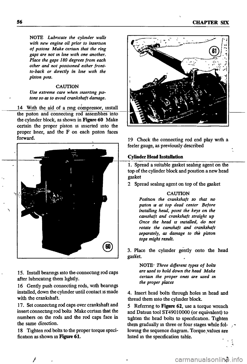
14
With
the
aid
of
a
nng
compressor
illStaIl
the
pISton
and
connectmg
rod
assembhes
into
the
cyhnder
block
as
shown
in
Figure
60
Make
certain
the
proper
piston
IS
mserted
mto
the
proper
hner
and
the
F
on
each
pISton
faces
forward
@
15
Install
beanngs
mto
the
connectIng
rod
caps
after
lubncatmg
them
hghtly
16
Gently
push
connecting
rods
With
beanngs
installed
down
the
cyhnder
until
contact
IS
made
with
the
crankshaft
17
Set
connectIng
rod
caps
over
crankshaft
and
insert
COnnectIng
rod
bolts
Make
certam
that
the
numbers
on
the
rods
and
the
rod
caps
face
in
the
same
direction
18
Tighten
rod
bolts
to
the
proper
torque
speci
ficatIon
as
shown
m
Figure
61
I
J
@v
N
i
19
Check
the
connecting
rod
end
play
With
a
feeler
gauge
as
previously
described
Cylinder
Head
Installation
1
Spread
a
suitable
gasket
seahng
agent
on
the
top
of
the
cylinder
block
and
position
a
new
head
gasket
2
Spread
seahng
agent
on
top
of
the
gasket
CAUTION
PositIon
the
crankshaft
so
that
no
pzston
IS
at
top
dead
center
Before
installing
head
point
the
keys
on
the
camshaft
and
crankshaft
straight
up
Once
the
head
zs
Installed
do
not
rotate
the
camshaft
and
crankshaft
separately
as
damage
to
the
piston
tops
might
result
3
Place
the
cyhnder
gently
onto
the
head
gask
et
NOTE
Three
dIfferent
types
of
bolts
are
used
to
hold
down
the
head
Make
certain
the
proper
ones
are
used
In
the
proper
places
4
Insert
head
bolts
through
holes
ill
head
and
thread
them
mto
the
cyhnder
block
5
Refemng
to
Figure
62
use
a
torque
wrench
and
Datsun
tool
ST49010000
or
equivalent
to
tIghten
the
head
bolts
to
specIficatIon
Tighten
them
gradually
m
three
or
four
stages
wlnle
fol
lOWIng
the
sequence
diagram
Torque
values
are
hsted
m
the
specIfication
table
Page 62 of 252
ENGINE
57
@
L
13
and
L
16
engme
000000
8
4
2
6
10
7
3
1
5
9
o
0
0
0
0
Front
Crankshaft
and
Timing
Chain
Assembly
1
Insert
a
woodruff
key
mto
the
crankshaft
key
way
and
slide
the
crankshaft
sprocket
mto
place
2
Insert
a
woodruff
key
m
the
Illiddle
crank
shaft
keyway
and
slide
the
dIstnbutor
dnve
gear
mto
place
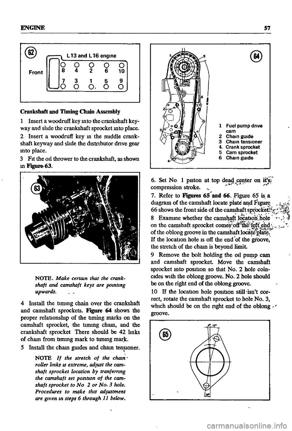
3
FIt
the
oil
thrower
to
the
crankshaft
as
shown
m
Figure
63
NOTE
Make
certam
that
the
crank
shaft
and
camshaft
keys
are
polntlng
upwards
4
Install
the
tmung
chain
over
the
crankshaft
and
camshaft
sprockets
Figure
64
shows
the
proper
relatIonslnp
of
the
tIming
marks
on
the
camshaft
sprocket
the
tmung
cham
and
the
crankshaft
sprocket
There
should
be
42
hnks
of
cham
from
tmung
mark
to
tmung
mar
k
5
Install
the
cham
gwdes
and
cham
tensIoner
NOTE
If
the
stretch
of
the
cham
roller
links
IS
extreme
adJust
the
cam
shaft
sprocket
location
by
tranfernng
the
camshaft
set
pOSltlon
of
the
cam
shaft
sprocket
to
No
2
or
No
3
hole
Procedures
to
make
thIS
adJustment
are
gIVen
m
steps
6
through
II
below
@
1
Fuel
pump
drive
eam
2
Cham
gUide
3
Cham
tensloner
4
Crank
sprocket
5
Cam
sprocket
6
Cham
gUide
6
Set
N
1
pISton
at
top
de
8
n
r
on
f
compressIon
stroke
7
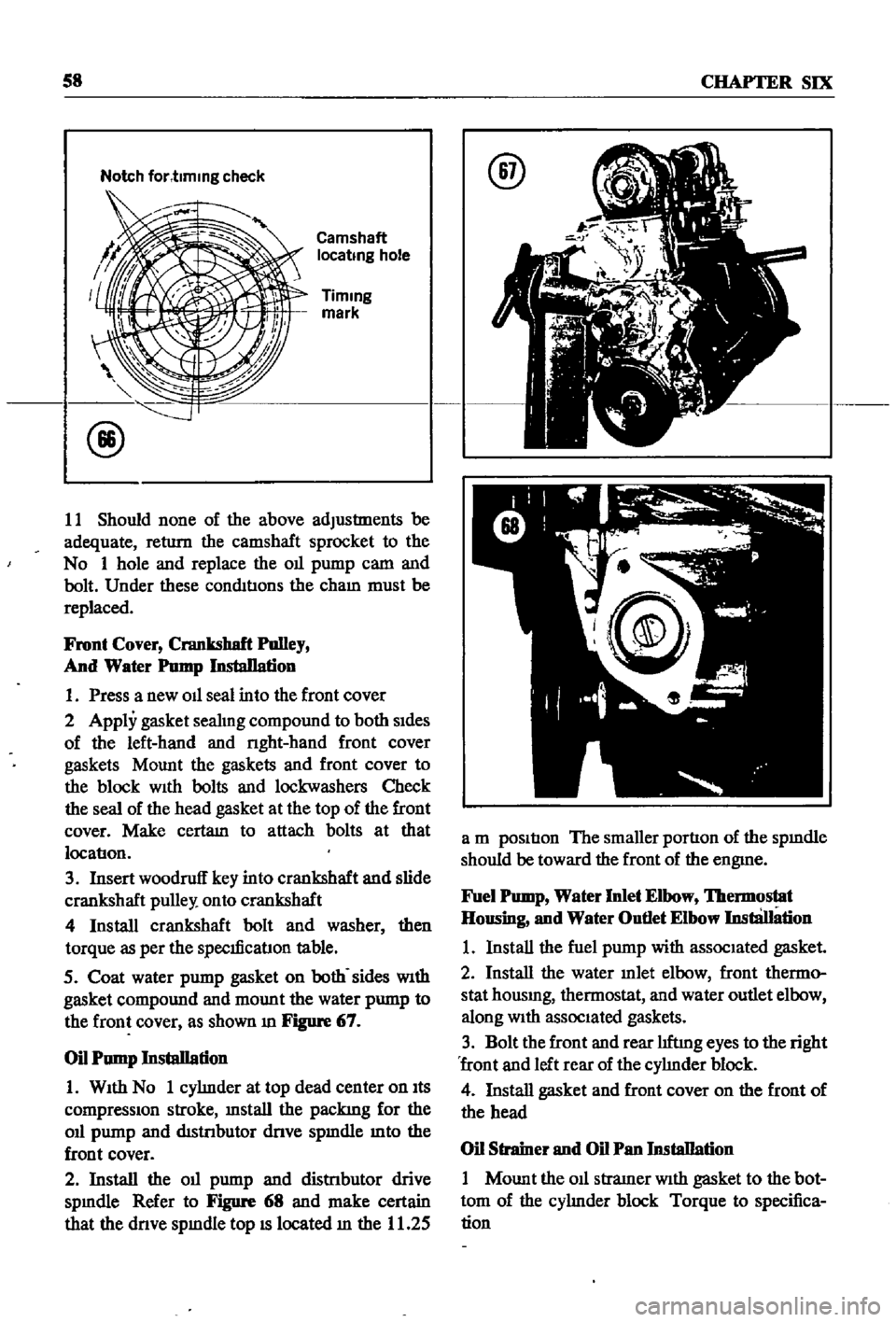
Refer
to
Figures
65
and
66
Figure
65
is
a
dIagram
of
the
camshaft
locate
piate
an
d
FI
1
66
shows
the
front
side
of
the
camshaft
sprOcKee5
r
11
r
If
8
Examme
whether
the
camshaft
locatIon
hole
y
on
the
camshaft
sprocket
com
ff
llii
sl
ff
end
foI
tri4o
of
the
oblong
groove
in
the
camshaft
locate
E
1litc
If
the
locatIon
hole
IS
off
the
end
of
the
groove
the
stretch
of
the
cham
is
beyond
limit
9
Remove
the
bolt
holding
the
oil
pwp
p
cam
and
camshaft
sprocket
Move
the
camshaft
sprocket
mto
posItIon
so
that
No
2
hole
coin
Cides
With
the
oblong
groove
No
2
hole
should
be
on
the
right
end
of
the
oblong
groove
10
If
the
locatIon
hole
posItIon
still
isn
t
cor
rect
rotate
the
camshaft
sprocket
to
hole
No
3
which
should
be
on
the
nght
end
of
the
oblong
groove
@
Page 63 of 252
58
CHAPTER
SIX
Notch
for
t1mmg
check
Camshaft
locatmg
hole
Timmg
mark
11
Should
none
of
the
above
adjustments
be
adequate
return
the
camshaft
sprocket
to
the
No
1
hole
and
replace
the
Oll
pump
cam
and
bolt
Under
these
conditIons
the
cham
must
be
replaced
Front
Cover
Crankshaft
Polley
And
Water
Pomp
InstaDation
1
Press
a
new
Oll
seal
into
the
front
cover
2
Apply
gasket
seahng
compound
to
both
sides
of
the
left
hand
and
nght
hand
front
cover
gaskets
Mount
the
gaskets
and
front
cover
to
the
block
With
bolts
and
lockwashers
Check
the
seal
of
the
head
gasket
at
the
top
of
the
front
cover
Make
certam
to
attach
bolts
at
that
locatlon
3
Insert
woodruff
key
into
crankshaft
and
slide
crankshaft
pulley
onto
crankshaft
4
Install
crankshaft
bolt
and
washer
then
torque
as
per
the
speclficatlon
table
5
Coat
water
pump
gasket
on
both
sides
With
gasket
compound
and
mount
the
water
pump
to
the
front
cover
as
shown
m
Figure
67
Oil
Pump
Installation
1
With
No
1
cyhnder
at
top
dead
center
on
Its
compressIOn
stroke
mstall
the
packing
for
the
Oll
pump
and
distnbutor
dnve
spmdle
mto
the
front
cover
2
Install
the
Oll
pump
and
distnbutor
drive
spmdle
Refer
to
Figure
68
and
make
certain
that
the
dnve
spmdle
top
IS
located
m
the
11
25
@
a
m
position
The
smaller
portion
of
the
spmdle
should
be
toward
the
front
of
the
engme
Fuel
Pomp
Water
Inlet
Elbow
lbermostat
Housing
and
Water
Outlet
Elbow
InstliJIation
1
Install
the
fuel
pump
with
associated
gasket
2
Install
the
water
mlet
elbow
front
thermo
stat
housmg
thermostat
and
water
outlet
elbow
along
With
associated
gaskets
3
Bolt
the
front
and
rear
hftmg
eyes
to
the
right
front
and
left
rear
of
the
cyhnder
block
4
Install
gasket
and
front
cover
on
the
front
of
the
head
Oil
Strainer
and
Oil
Pan
Installation
1
Mount
the
011
stramer
With
gasket
to
the
bot
tom
of
the
cyhnder
block
Torque
to
specifica
tion
Page 64 of 252

ENGINE
59
2
Coat
the
pan
gasket
on
both
sides
With
gasket
compound
and
attach
the
oil
pan
to
the
cyhnder
block
Torque
as
specIfied
Manifold
and
Carburetor
Installation
1
Install
the
mtake
and
exhaust
manIfolds
WIth
associated
gasket
to
the
cylmder
head
2
Mount
the
carburetor
and
gasket
to
the
mtake
manIfold
2
Adjust
all
mtake
and
exhaust
valves
to
the
specIfied
clearance
for
a
cold
engme
Clutch
Assembly
Installation
CAUTION
Take
extreme
care
not
to
get
grease
or
011
on
the
clutch
or
flywheel
frlc
hon
contact
surfaces
1
Place
the
clutch
disc
assembly
on
the
flywheel
With
the
longer
chamfered
splmed
end
of
the
dISC
toward
the
transmISSion
2
Visually
align
or
use
a
dummy
splmed
dnve
shaft
to
ahgn
the
diSC
assembly
With
the
flywheel
pilot
beanng
3
Install
and
tighten
the
SIX
bolts
holdmg
the
clutch
cover
assembly
to
the
flywheel
Tighten
the
bolts
a
turn
each
tune
by
diagonal
pattern
until
they
are
tight
Tlghtenmg
torque
should
be
174
to
188ft
lbs
24
to
2
6
kg
m
NOTE
There
are
two
dowels
on
the
flywheel
to
locate
the
clutch
cover
4
Remove
dummy
shaft
If
used
after
the
above
bolts
are
fully
tightened
5
Refit
the
release
bearing
and
translI11Ssion
case
Miscellaneous
Installation
1
Connect
the
fuel
hose
on
the
front
part
of
the
engme
to
the
fuel
pump
and
to
the
carburetor
2
Gap
the
spark
plugs
and
mstall
them
usmg
new
gaskets
3
Coat
the
rocker
arm
cover
gasket
With
sealer
and
position
It
on
the
cylmder
head
4
Install
the
rocker
arm
cover
and
tighten
the
two
thumb
screws
that
hold
it
m
place
5
Install
distrIbutor
makmg
certam
that
the
notch
on
the
distributor
shaft
assembly
mates
With
the
drive
spmdle
Ahgn
the
location
marks
made
dunng
disassembly
so
that
the
distrIbutor
is
positioned
as
before
6
Install
and
tighten
the
bolts
which
hold
the
dIStributor
to
the
front
cover
7
Install
pomts
condenser
and
rotor
8
Replace
distrIbutor
cap
and
attach
spark
plug
Wires
m
the
correct
sequence
Make
certain
that
all
wires
are
firmly
seated
m
the
distrIbutor
cap
and
attached
securely
to
the
spark
plugs
9
HOISt
the
engme
assembly
from
the
work
stand
10
Install
the
alternator
bracket
alternator
and
engme
mounts
to
the
block
11
Install
the
IgnItIon
coil
oil
filter
oil
pressure
SWitch
dipstick
and
water
drain
plug
12
Connect
the
vacuum
Ime
between
the
dis
trIbutor
and
carburetor
13
Connect
the
transIDlSSlOn
to
the
engine
prior
to
mstallatIon
m
the
vehicle
Engine
Installation
Installation
is
the
reverse
of
the
procedures
followed
m
removal
Be
certaIn
thatlall
battery
connections
are
made
that
water
hoses
are
se
cured
wmng
IS
connected
properly
and
that
all
required
bolts
and
mounts
are
mstalled
and
tightened
Replace
the
radiator
fan
belts
and
radiator
shroud
Fill
the
engme
With
the
proper
grade
of
oil
and
the
radiator
With
recommended
coolant
Install
the
hood
to
the
hInges
according
to
the
marks
made
dUrIng
removal
SERVICE
DATA
AND
SPECIFICATIONS
Table
1
covers
servIce
data
and
engme
Speci
fications
 1
1 2
2 3
3 4
4 5
5 6
6 7
7 8
8 9
9 10
10 11
11 12
12 13
13 14
14 15
15 16
16 17
17 18
18 19
19 20
20 21
21 22
22 23
23 24
24 25
25 26
26 27
27 28
28 29
29 30
30 31
31 32
32 33
33 34
34 35
35 36
36 37
37 38
38 39
39 40
40 41
41 42
42 43
43 44
44 45
45 46
46 47
47 48
48 49
49 50
50 51
51 52
52 53
53 54
54 55
55 56
56 57
57 58
58 59
59 60
60 61
61 62
62 63
63 64
64 65
65 66
66 67
67 68
68 69
69 70
70 71
71 72
72 73
73 74
74 75
75 76
76 77
77 78
78 79
79 80
80 81
81 82
82 83
83 84
84 85
85 86
86 87
87 88
88 89
89 90
90 91
91 92
92 93
93 94
94 95
95 96
96 97
97 98
98 99
99 100
100 101
101 102
102 103
103 104
104 105
105 106
106 107
107 108
108 109
109 110
110 111
111 112
112 113
113 114
114 115
115 116
116 117
117 118
118 119
119 120
120 121
121 122
122 123
123 124
124 125
125 126
126 127
127 128
128 129
129 130
130 131
131 132
132 133
133 134
134 135
135 136
136 137
137 138
138 139
139 140
140 141
141 142
142 143
143 144
144 145
145 146
146 147
147 148
148 149
149 150
150 151
151 152
152 153
153 154
154 155
155 156
156 157
157 158
158 159
159 160
160 161
161 162
162 163
163 164
164 165
165 166
166 167
167 168
168 169
169 170
170 171
171 172
172 173
173 174
174 175
175 176
176 177
177 178
178 179
179 180
180 181
181 182
182 183
183 184
184 185
185 186
186 187
187 188
188 189
189 190
190 191
191 192
192 193
193 194
194 195
195 196
196 197
197 198
198 199
199 200
200 201
201 202
202 203
203 204
204 205
205 206
206 207
207 208
208 209
209 210
210 211
211 212
212 213
213 214
214 215
215 216
216 217
217 218
218 219
219 220
220 221
221 222
222 223
223 224
224 225
225 226
226 227
227 228
228 229
229 230
230 231
231 232
232 233
233 234
234 235
235 236
236 237
237 238
238 239
239 240
240 241
241 242
242 243
243 244
244 245
245 246
246 247
247 248
248 249
249 250
250 251
251


