Page 65 of 252

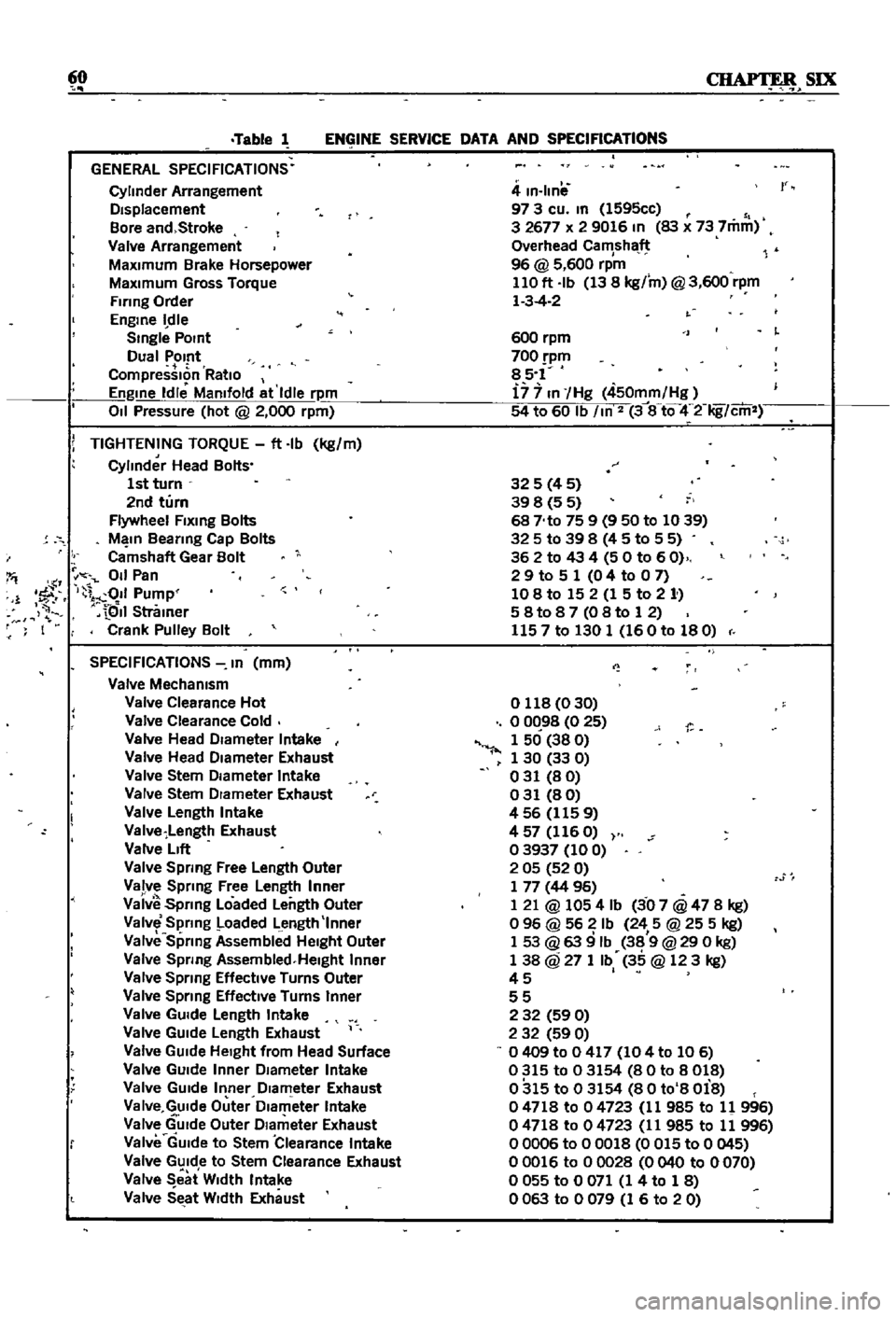
60
SIX
Table
1
ENGINE
SERVICE
DATA
AND
SPECIFICATIONS
GENERAL
SPECIFICATIONS
Cylinder
Arrangement
DIsplacement
Bore
and
Stroke
Valve
Arrangement
MaxImum
Brake
Horsepower
MaxImum
Gross
Torque
Firing
Order
Engme
dle
Smgle
POint
Dual
Pomt
CompressIon
RatIo
Engme
Idle
Mamfold
at
Idle
rpm
011
Pressure
hot
@
2
000
rpm
i
TIGHTENING
TORQUE
ft
Ib
kg
m
Cylinder
Head
Bolts
1st
turn
2nd
turn
Flywheel
Flxmg
Bolts
M
In
Beanng
Cap
Bolts
Camshaft
Gear
Bolt
I
011
Pan
1
1
fF
I
011
Pump
QII
Stramer
F
I
Crank
Pulley
Bolt
SPECIFICATIONS
In
mm
Valve
Mechamsm
Valve
Clearance
Hot
Valve
Clearance
Cold
Valve
Head
DIameter
Intake
Valve
Head
DIameter
Exhaust
Valve
Stem
DIameter
Intake
Valve
Stem
DIameter
Exhaust
Valve
Length
Intake
Valve
Length
Exhaust
Valve
LIft
Valve
Spring
Free
Length
Outer
Valve
Sprmg
Free
Length
Inner
Vaiv
Spnng
Loaded
Length
Outer
Valve
Spring
Loaded
Length
Inner
Valve
Sprmg
Assembllld
HeIght
Outer
Valve
Spnng
Assembled
Helght
Inner
Valve
Spnng
Effective
Turns
Outer
Valve
Sprmg
EffectIve
Turns
Inner
Valve
GUIde
Length
Intake
Valve
GUIde
Length
Exhaust
Valve
GUIde
HeIght
from
Head
Surface
Valve
GUIde
Inner
DIameter
Intake
Valve
GUIde
Inner
DIameter
Exhaust
Va
Ive
GUIde
Outer
Dlam
eter
Intake
Valve
GUIde
Outer
DIameter
Exhaust
Valve
GUIde
to
Stem
Clearance
Intake
Valve
GUIde
to
Stem
Clearance
Exhaust
Valve
eat
W
dth
Intake
Valve
SEtat
WIdth
Exhaust
4
m
Ilnil
97
3
cu
m
1595cc
3
2677
x
2
9016
In
83
x
73
7mm
Overhead
Camshaft
96
@
5
600
rpm
110
ft
Ib
13
8
kg
m
@
3
600
rpm
1
3
4
2
r
600
rpm
700
pm
85
1
i7
7
In
Hg
450mm
Hg
54
to
60
Ib
m
2
3
8
tQ
4
2
Iig
cm
325
4
5
39
8
5
5
68
No
75
9
9
50
to
1039
325
to
39
8
4
5
to
5
5
362
to
43
4
50
to
60
2
9
to
5
1
0
4
to
0
7
108
to
15
2
1
5
to
2
1
58t087
08to
12
1157
to
130
1
160
to
180
o
118
0
30
o
0C
98
0
25
1
50
38
0
1
30
33
0
031
80
031
80
456
1159
4
57
116
O
03937
100
2
05
52
0
1
77
44
96
1
21
@
1054
Ib
3
07
@
47
8
kg
o
96
@
56
Ib
24
5
@
25
5
kg
1
53
@
63
9
Ib
38
9
@
29
0
kg
1
38
@
27
1
Ib
35
@
123
kg
45
I
55
2
32
59
0
2
32
59
0
0409
to
0
417
104
to
106
0315
to
03154
80
to
8018
0315
to
03154
80
to
8
Oi8
04718
to
04723
11
985
to
11
996
04718
to
04723
11
985
to
11
996
00006
to
00018
0
015
to
0
045
00016
to
00028
0040
to
0070
o
055
to
0
071
1
4
to
1
8
0063
to
0079
1
6
to
20
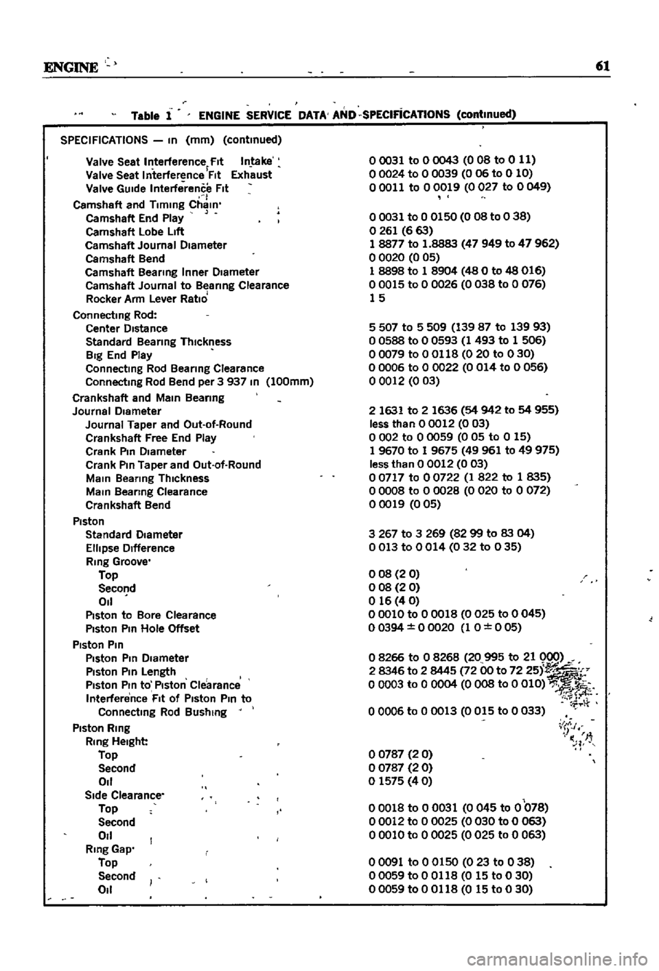
Page 66 of 252

ENGINE
61
SPECIFICATIONS
In
mm
continued
Valve
Seat
Interference
Fit
Intake
Valve
Seat
Interference
Flt
Exh
ust
Valve
GUide
Interference
fit
I
Camshaft
and
Timing
Chain
Ca
mshaft
End
Play
Camshaft
Lobe
LIft
Camshaft
Journal
Diameter
Camshaft
Bend
Camshaft
Bearing
Inner
Diameter
Camshaft
Journal
to
B
arlng
Clearance
Rocker
Arm
Lever
Ratio
Connecting
Rod
Center
Distance
Standard
Bearing
Thickness
Big
End
Play
Connectmg
Rod
Beanng
Clearance
Connecting
Rod
Bend
per
3
937
In
100mm
Crankshaft
and
Main
Beanng
Journal
Diameter
Journal
Taper
and
Out
ot
Round
Crankshaft
Free
End
Play
Crank
Pin
Diameter
Crank
Pin
Taper
and
Out
ot
Round
Main
Bearing
Thickness
Main
Beanng
Clearance
Crankshaft
Bend
Piston
Standard
Diameter
Ellipse
Difference
Ring
Groove
Top
Second
011
Piston
to
Bore
Clearance
Piston
Pm
Hole
Offset
Piston
Pin
Piston
Pin
Diameter
Piston
Pin
Length
Piston
Pin
to
Piston
Clearance
Interference
Fit
ot
Piston
Pin
to
Connecting
Rod
Bushing
Piston
Ring
Ring
Height
Top
Second
011
Side
Clearance
Top
Second
011
Ring
Gap
Top
Second
011
Table
1
ENGINE
SERVICE
DATA
AND
SPECIFicATIONS
continued
00031
to
0
0043
0
OB
to
0
11
00024
to
0
0039
006
to
0
10
00011
to
00019
0027
to
0049
00031
to
0
0150
0
08
to
0
38
o
261
6
63
18877
to
1
8883
47
949
to
47
962
o
0020
0
05
1
8898
to
1
8904
48
0
to
48
016
00015
to
0
0026
0038
to
0
076
15
5
507
to
5
509
139
87
to
139
93
o
0588
to
0
0593
1
493
to
1
506
00079
to
0
0118
0
20
to
030
o
0006
to
0
0022
0
014
to
0
056
o
0012
003
2
1631
to
2
1636
54
942
to
54
955
less
than
00012
003
o
002
to
0
0059
0
05
to
0
15
1
9670
to
1
9675
49961
to
49
975
less
than
0
0012
0
03
o
0717
to
0
0722
1
822
to
1
835
o
0008
to
0
0028
0
020
to
0
072
00019
005
3267
to
3
269
8299
to
83
04
0013
to
0014
032
to
035
008
20
o
08
2
0
o
16
4
0
00010
to
0
0018
0
025
to
0
045
00394
0
0020
1
O
0
05
o
8266
to
0
8268
20
995
to
21
0
0
2
8346
to
2
8445
72
00
to
72
251
o
0003
to
0
0004
0
OOS
to
0
OlD
00006
to
0
0013
0015
to
0
033
o
0787
2
0
o
0787
2
0
o
1575
40
00018
to
00031
0
045
to
0
078
00012
to
0
0025
0030
to
0
063
00010
to
00025
0025
to
0
063
i
J
I
n
T
00091
to
0
0150
023
to
038
00059
to
0
0118
0
15
to
0
30
00059
to
0
0118
0
15
to
0
30
Page 67 of 252

CHAPTER
SEVEN
FUEL
SYSTEM
The
fuel
system
mcludes
the
fuel
tank
straIner
pump
carburetor
arr
cleaner
and
necessary
lines
Inspect
components
for
leaks
and
deterioratIOn
whenever
mamtenance
is
done
The
fuel
stramer
should
be
mspected
peri
odIcally
and
cleaned
AIR
CLEANER
The
au
filter
element
is
viscous
paper
and
does
not
require
cleanmg
Replace
It
every
24
000
mlles
or
more
frequently
under
harsh
condItIons
Several
mInor
differences
exist
between
vehicles
dependmg
on
the
type
of
emisSIOn
con
trol
device
used
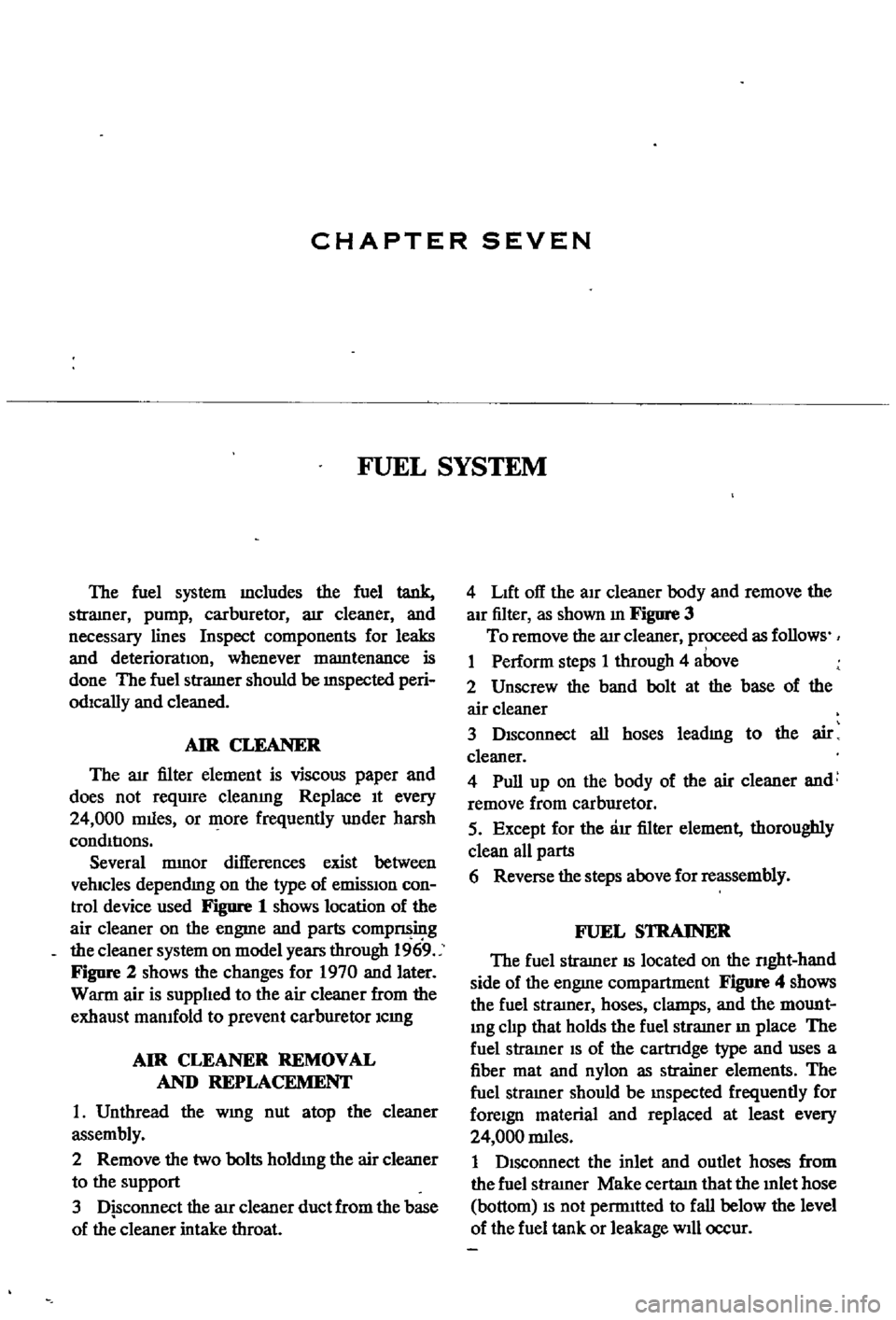
Figure
1
shows
location
of
the
air
cleaner
on
the
engme
and
parts
compnsing
the
cleaner
system
on
model
years
through
1969
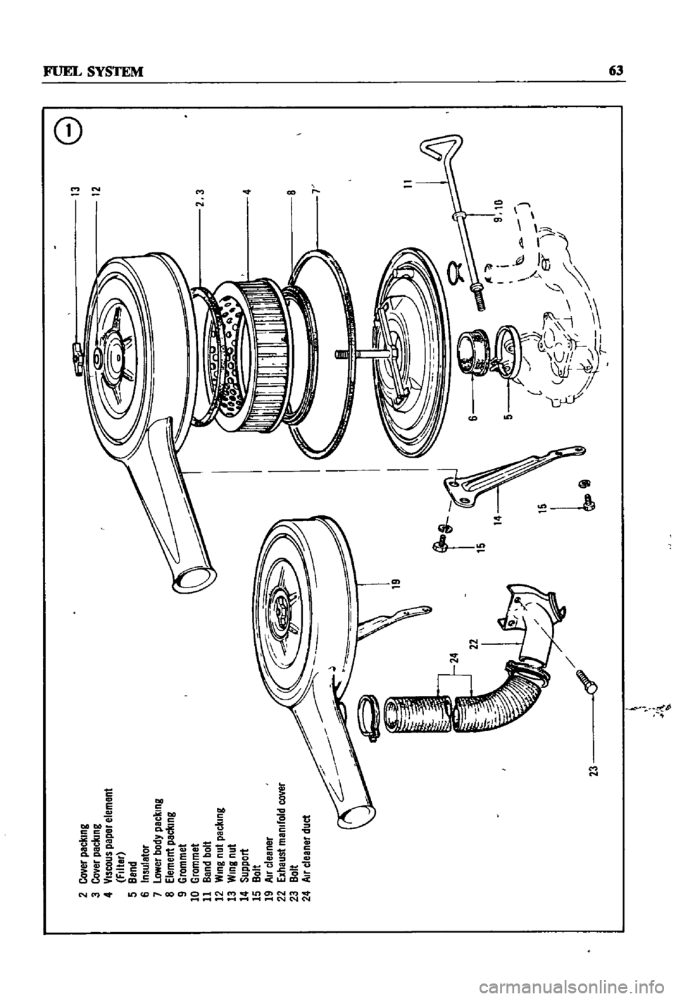
Figure
2
shows
the
changes
for
1970
and
later
Warm
air
is
supplIed
to
the
air
cleaner
from
the
exhaust
mamfold
to
prevent
carburetor
Icmg
AIR
CLEANER
REMOVAL
AND
REPLACEMENT
1
Unthread
the
WIng
nut
atop
the
cleaner
assembly
2
Remove
the
two
bolts
holdIng
the
air
cleaner
to
the
support
3
Disconnect
the
aIr
cleaner
duct
from
the
base
of
the
cleaner
intake
throat
4
LIft
off
the
aIr
cleaner
body
and
remove
the
aIr
filter
as
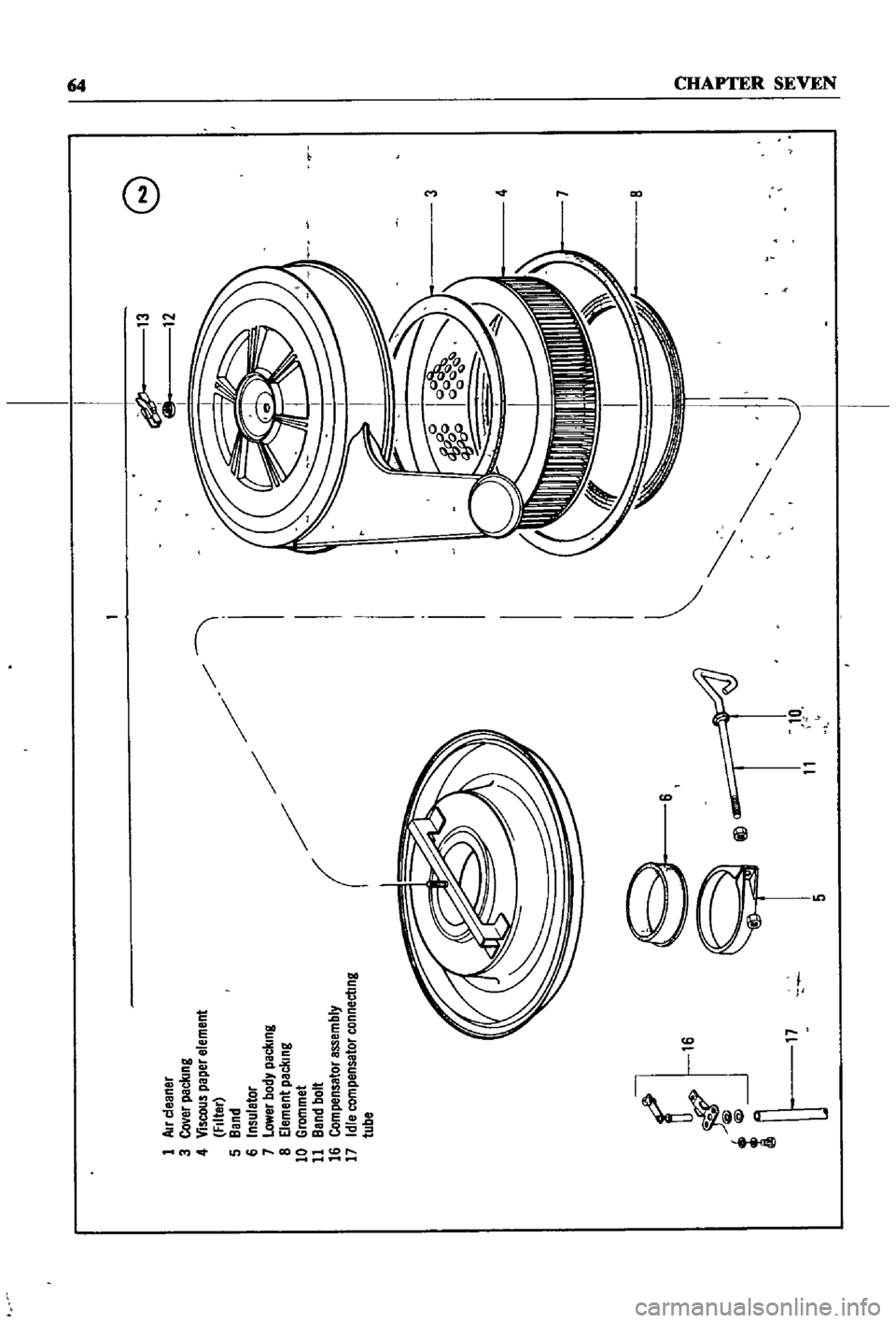
shown
m
Figure
3
To
remove
the
arr
cleaner
proceed
as
follows
1
Perform
steps
1
through
4
above
2
Unscrew
the
band
bolt
at
the
base
of
the
air
cleaner
3
DIsconnect
all
hoses
leadmg
to
the
air
cleaner
4
Pull
up
on
the
body
of
the
air
cleaner
and
remove
from
carburetor
5
Except
for
the
au
filter
element
thoroughly
clean
all
parts
6
Reverse
the
steps
above
for
reassembly
FUEL
STRAINER
The
fuel
stramer
IS
located
on
the
nght
hand
side
of
the
engme
compartment
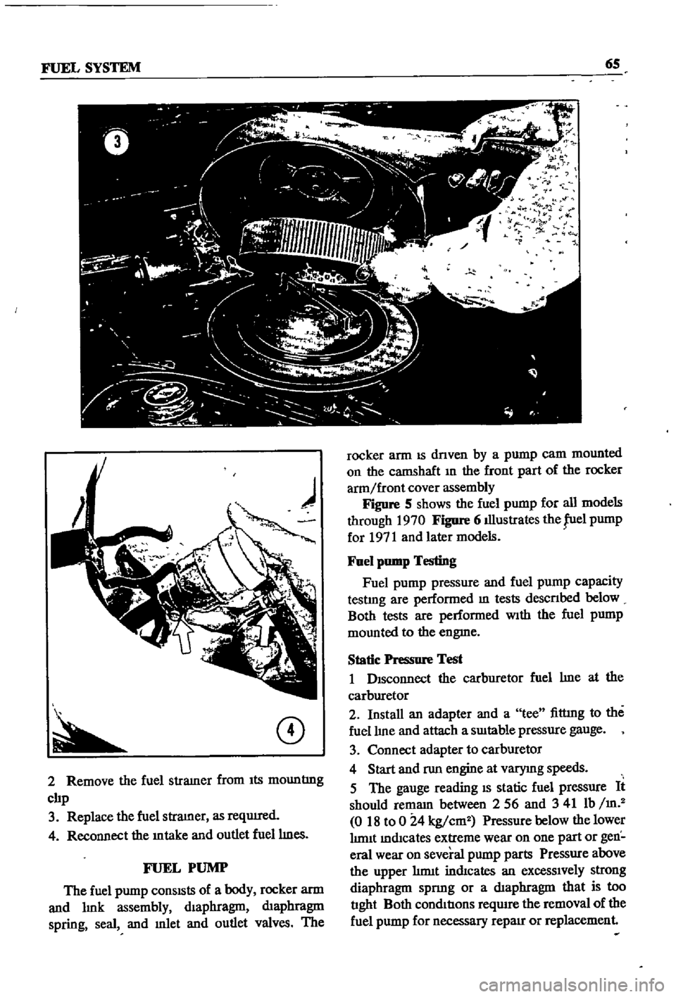
Figure
4
shows
the
fuel
stratner
hoses
clamps
and
the
mount
Ing
clIp
that
holds
the
fuel
stramer
In
place
The
fuel
stramer
IS
of
the
cartrIdge
type
and
uses
a
fiber
mat
and
nylon
as
strainer
elements
The
fuel
stramer
should
be
mspected
frequently
for
foreIgn
material
and
replaced
at
least
every
24
000
rmles
1
DIsconnect
the
inlet
and
outlet
hoses
from
the
fuel
stratner
Make
certatn
that
the
mlet
hose
bottom
IS
not
permItted
to
fall
below
the
level
of
the
fuel
tank
or
leakage
wIll
occur
Page 68 of 252
13
8
t
12
i
l
2
cover
packIng
3
Co
er
packIng
n
4
VISCOUS
paper
eleme
23
filter
5
Band
6
Insuletor
OWer
body
pecking
1
Element
pac
l
lng
liL
J
J
4
9
Grommet
10
Grommet
11
Band
bolt
lll
i
8
12
WIng
nut
packing
13
Wing
nut
AV
T
14
support
15
Ilolt
19
I
Il
cleaner
cover
22
ExhaUst
manIfold
23
Ilolt
24
I
Il
cleaner
duct
i
9
10
S
e
l
ci
r
C
t
f
J
14
IS
13
1
0
lot
Page 69 of 252
1
Air
cleaner
3
Co
er
paclung
4
Viscous
paper
element
FIlter
5
Band
6
Insuletor
7
Lower
body
packmg
8
Element
peclllng
10
Grommet
11
Band
bolt
16
Compensator
assembly
17
Idle
compensator
connectmg
tube
l
1
1
@
5
11
10
I
13
12
G
3
4
7
0
g
l
i
Page 70 of 252

FUEL
SYSTEM
6S
CD
2
Remove
the
fuel
stramer
from
Its
mountlng
clIp
3
Replace
the
fuel
stramer
as
reqUIred
4
Reconnect
the
mtake
and
outlet
fuellmes
FUEL
PUMP
The
fuel
pump
conSISts
of
a
body
rocker
arm
and
lmk
assembly
dIaphragm
dIaphragm
spring
seal
and
mlet
and
outlet
valves
The
l
r
t
1
9
l
F
r
fl
rocker
arm
IS
dnven
by
a
pump
cam
mounted
on
the
catnShaft
In
the
front
part
of
the
rocker
arm
front
cover
assembly
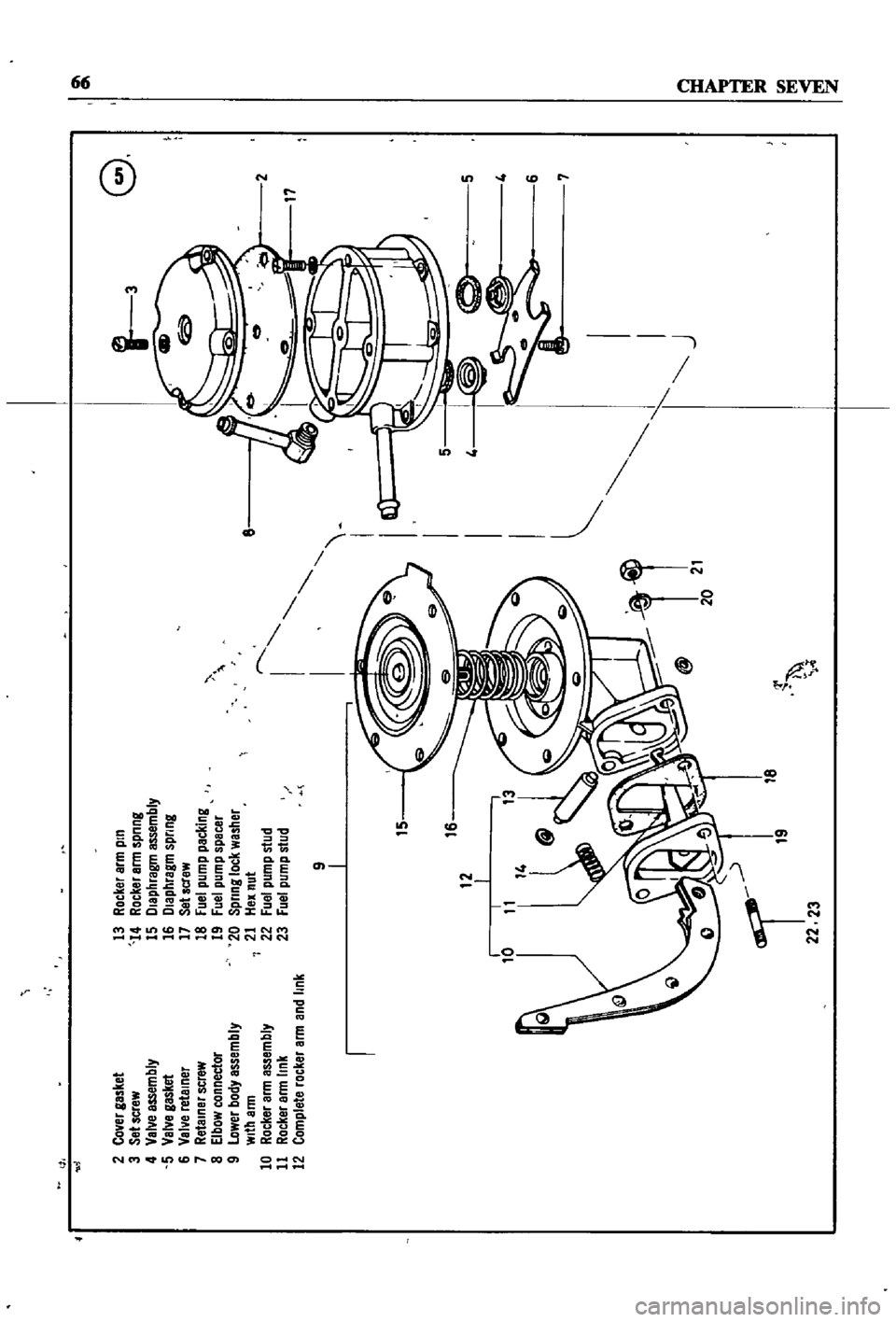
Figure
S
shows
the
fuel
pump
for
all
models
through
1970
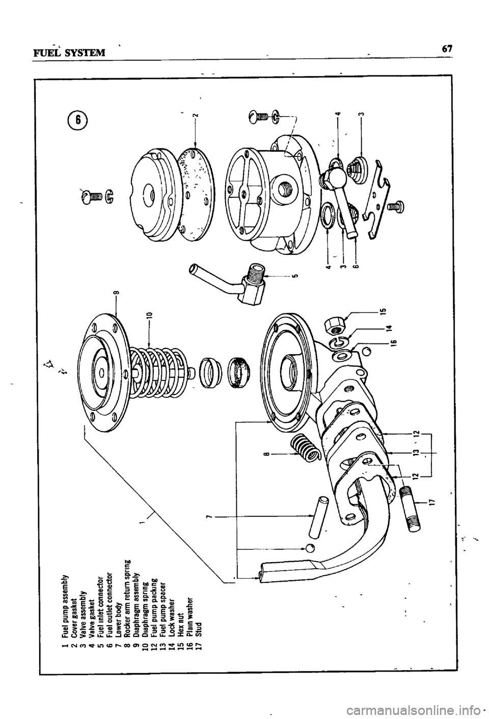
Figure
6
illustrates
the
fuel
pump
for
1971
and
later
models
Fuel
pump
Testing
Fuel
pump
pressure
and
fuel
pump
capacity
testlng
are
performed
m
tests
descnbed
below
Both
tests
are
performed
With
the
fuel
pump
mounted
to
the
engme
Static
Pressure
Test
1
DIsconnect
the
carburetor
fuel
lme
at
the
carburetor
2
Install
an
adapter
and
a
tee
fittmg
to
the
fuel
lIne
and
attach
a
SUItable
pressure
gauge
3
Connect
adapter
to
carburetor
4
Start
and
run
engine
at
varymg
speeds
5
The
gauge
reading
IS
static
fuel
pressure
It
should
remam
between
256
and
341
Ib
m
2
018
to
0
24
kg
cm2
Pressure
below
thelower
lImIt
mdlcates
extreme
wear
on
one
part
or
gen
eral
wear
on
several
pump
parts
Pressure
above
the
upper
hrmt
indIcates
an
excessIvely
strong
diaphragm
spnng
or
a
dIaphragm
that
is
too
tIght
Both
condItIons
require
the
removal
of
the
fuel
pump
for
necessary
repaIr
or
replacement
Page 71 of 252
01
01
G
1
3
2
Co
er
gasket
3
Set
screw
4
Val
e
assembly
5
Val
e
gasket
6
Val
e
retelner
7
Retainer
screw
8
Elbow
connector
9
lower
body
assembly
With
arm
10
Rocker
arm
assembly
11
Rocker
arm
link
12
Complete
rocker
arm
and
link
13
Rocker
arm
pin
14
Rocker
arm
spnng
15
Dlephragm
assembly
16
Diaphragm
spring
17
Sehcrew
18
Fuel
pump
pecking
19
Fuel
pump
spacer
20
Spnng
lock
washer
21
Hex
nut
22
Fuel
pump
stud
23
Fuel
pump
stud
2
17
r
I
I
I
I
I
I
I
I
I
J
9
I
I
15
I
0
5
I
16
1i
20
21
g
tI
i
I
lb
18
22
23
r
Page 72 of 252
G
i
@
1
fuel
pump
assembly
2
CoVBr
gasket
3
VBNB
assemblY
4
VBNB
gBsl
et
5
Fuel
Inlet
connect01
6
fUBI
outlet
connector
7
OwerllodY
a
Rocker
Bll
Ireturn
spnng
9
l
IBP
1rBgm
BssemblY
10
l
IBphlBgm
sQnng
12
Fuel
QumQ
packIng
13
fuel
pump
spBcer
14
lOc
l
wBsl
er
15
lex
nut
16
PIBIn
was
1Br
17
Stud