Page 1210 of 3229

The ECM us es t he informati on from the downs tream HO2S t o enhance the s ignals from t he upst ream HO2S.
The downst ream HO2S are si mi lar in their const ructi on t o t he ups t ream HO2S wit h t he except ion of t he out put si gnal t ot he ECM. The out put si gnal i s a binary s ignal where t he amplit ude of the si gnal curve changes consi derably when t heoxygen content in the exhaust gas s es changes . The oxygen content of t he exhaus t gas ses leaving t he catalyt ic converterare measured by comparing i t wit h ambi ent ai r drawn i nt o t he HO2S.
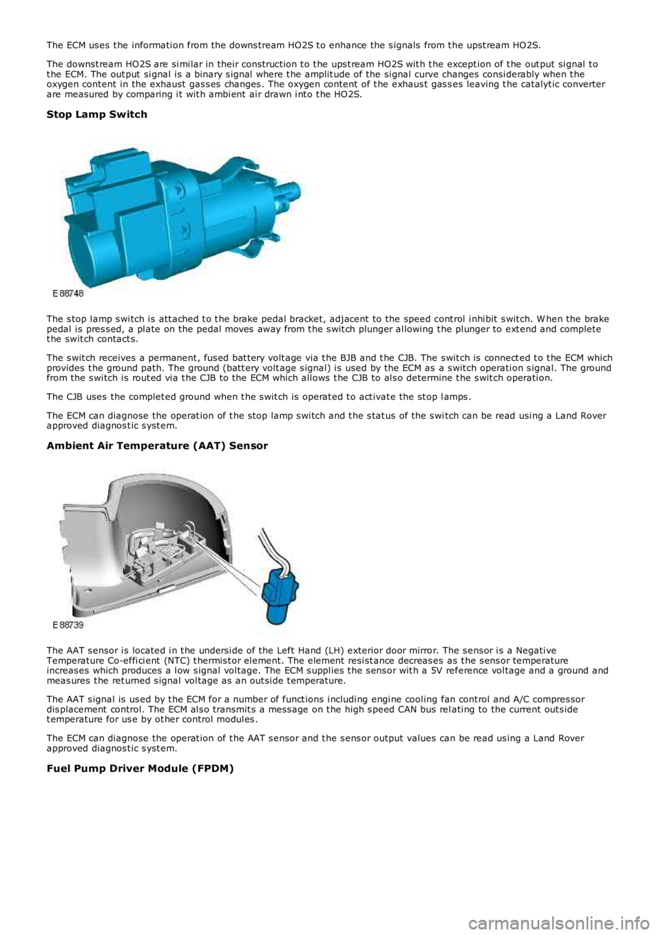
Stop Lamp Switch
The s top l amp s wi tch i s att ached t o t he brake pedal bracket, adjacent to the speed cont rol i nhi bit s wit ch. W hen the brakepedal i s pres s ed, a pl ate on the pedal moves away from t he s wit ch plunger al lowing the pl unger to ext end and completet he swit ch contact s.
The s wit ch receives a permanent , fus ed bat t ery volt age via t he BJB and t he CJB. The s wit ch is connect ed t o t he ECM whichprovides t he ground path. The ground (batt ery volt age s ignal) i s used by the ECM as a s wit ch operati on s ignal. The groundfrom the s wi tch i s rout ed vi a t he CJB to the ECM which all ows t he CJB to al s o determine t he s wit ch operati on.
The CJB uses the complet ed ground when t he s wit ch is operat ed t o act ivat e the st op lamps .
The ECM can diagnose the operat ion of t he s top lamp s wi tch and t he s tat us of the s witch can be read usi ng a Land Roverapproved diagnos t ic s yst em.
Ambient Air Temperature (AAT) Sensor
The AAT s ensor i s located i n t he undersi de of the Left Hand (LH) exterior door mirror. The s ens or i s a Negati veTemperature Co-effi ci ent (NTC) t hermis t or el ement. The element resi st ance decreas es as t he s ens or temperatureincreas es which produces a l ow s ignal vol tage. The ECM s uppl ies t he s ens or wit h a 5V reference vol tage and a ground andmeas ures t he ret urned s ignal vol tage as an out si de t emperature.
The AAT s ignal is us ed by t he ECM for a number of funct ions i ncludi ng engi ne cool ing fan cont rol and A/C compres sordis placement control. The ECM al s o transmit s a mes s age on t he high s peed CAN bus relati ng to the current out s idet emperature for us e by ot her control modul es .
The ECM can diagnose the operat ion of t he AAT s ensor and t he s ens or output values can be read us ing a Land Roverapproved diagnos t ic s yst em.
Fuel Pump Driver Module (FPDM)
Page 1215 of 3229

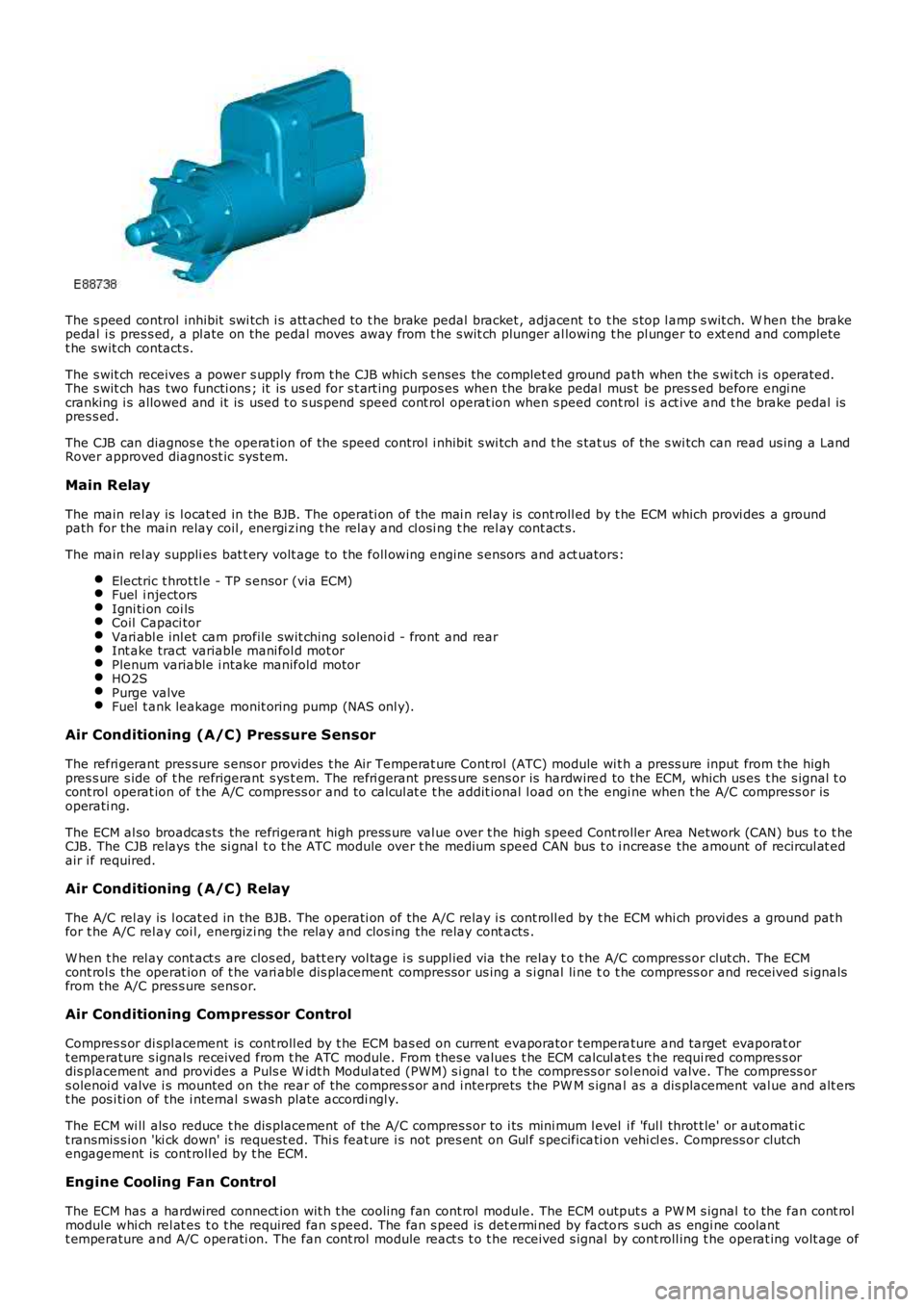
The s peed control inhibit swi tch i s att ached to t he brake pedal bracket , adjacent t o t he s top l amp s wit ch. W hen the brakepedal i s pres s ed, a pl ate on the pedal moves away from t he s wit ch plunger al lowing the pl unger to ext end and completet he swit ch contact s.
The s wit ch receives a power s upply from t he CJB which s enses the complet ed ground path when the s wi tch i s operated.The s wit ch has two functi ons ; it is us ed for s t art ing purpos es when the brake pedal mus t be pres s ed before engi necranking i s allowed and it is used t o s us pend speed cont rol operat ion when s peed cont rol i s act ive and t he brake pedal ispres s ed.
The CJB can diagnos e t he operat ion of t he speed control i nhibit s wi tch and t he s tat us of the s wi tch can read us ing a LandRover approved diagnost ic sys tem.
Main Relay
The main rel ay is l ocat ed in the BJB. The operati on of the mai n rel ay is cont roll ed by t he ECM which provi des a groundpath for the main relay coil , energi zing t he rel ay and cl osi ng t he rel ay cont act s.
The main rel ay suppli es bat t ery volt age to the foll owing engine s ensors and act uators:
Electric t hrot tl e - TP s ensor (via ECM)Fuel i njectorsIgni ti on coi lsCoil Capaci torVari abl e inl et cam profile swit ching sol enoi d - front and rearInt ake tract variable mani fol d mot orPlenum variable i ntake manifold motorHO2SPurge valveFuel t ank leakage monit oring pump (NAS onl y).
Air Conditioning (A/C) Pressure Sensor
The refri gerant pres sure s ens or provides t he Air Temperat ure Cont rol (ATC) module wit h a press ure input from t he highpres s ure s ide of t he refrigerant s ys t em. The refri gerant press ure s ens or is hardwired to the ECM, which us es t he s ignal t ocont rol operat ion of t he A/C compress or and to cal cul at e t he addit ional l oad on t he engi ne when t he A/C compress or isoperati ng.
The ECM al so broadcas ts the refrigerant high press ure val ue over t he high s peed Controller Area Network (CAN) bus t o t heCJB. The CJB relays the si gnal t o t he ATC module over t he medium speed CAN bus t o i ncreas e the amount of recircul at edair i f required.
Air Conditioning (A/C) Relay
The A/C rel ay is l ocat ed in the BJB. The operati on of the A/C relay i s cont roll ed by t he ECM whi ch provi des a ground pat hfor t he A/C rel ay coi l, energizi ng the relay and clos ing the relay cont acts .
W hen t he rel ay cont act s are clos ed, batt ery vol tage i s s uppl ied via the relay t o t he A/C compress or clut ch. The ECMcont rol s the operat ion of t he vari abl e dis placement compress or us ing a s i gnal li ne to t he compress or and received s ignalsfrom the A/C pres s ure sens or.
Air Conditioning Compressor Control
Compres s or di spl acement is cont roll ed by t he ECM bas ed on current evaporator t emperature and target evaporat ort emperature s ignals received from t he ATC module. From thes e values t he ECM calcul ates t he requi red compres s ordis placement and provi des a Puls e W idt h Modul ated (PW M) s i gnal t o t he compress or s olenoi d valve. The compress ors olenoi d valve i s mounted on the rear of t he compres s or and i nterprets the PW M s ignal as a dis placement val ue and alt erst he pos i ti on of the i nternal s wash plate accordi ngl y.
The ECM wi ll als o reduce t he dis placement of the A/C compres s or to i ts mini mum l evel i f 'ful l throt t le' or aut omati ct ransmis s ion 'ki ck down' is request ed. Thi s feat ure i s not pres ent on Gul f s pecificati on vehi cl es. Compress or clutchengagement is cont roll ed by t he ECM.
Engine Cooling Fan Control
The ECM has a hardwired connect ion wit h t he cooli ng fan cont rol module. The ECM output s a PW M s ignal to the fan cont rolmodule whi ch rel at es t o t he required fan s peed. The fan s peed is det ermi ned by factors s uch as engi ne coolantt emperature and A/C operati on. The fan cont rol module react s t o t he received s ignal by cont roll ing t he operat ing volt age of
Page 1223 of 3229
Publi s hed: 11-May-2011
Electronic Engine Controls - I6 3.2L Petrol - Camshaft Position (CMP)
Sensor
Removal and Inst all ati on
Removal
• NOTE: Removal s t eps in t his procedure may cont ain i nst all ati on det ail s.
Remove t he engi ne cover.
Refer t o: Engi ne Cover - I6 3.2L Pet rol (501-05 Int eri or Trim and
Ornament ati on, Removal and Ins tal lat ion).
1. 2.
3.
CAUTIONS: Not e t he fi tt ed pos it ion of t he special was her.
Di s card the seal.
T orque: 10 Nm 3.
Installation 1. CAUTIONS: Make s ure that t he mat ing faces are clean and free of
corros i on and forei gn mat erial . A new O-ri ng s eal i s to be ins tal led.
To i nst all , revers e t he removal procedure.
1.
Page 1224 of 3229
Publi s hed: 11-May-2011
Electronic Engine Controls - I6 3.2L Petrol - Crankshaft Position (CKP)
Sensor
Removal and Inst all ati on
Removal
• NOTE: Removal s t eps in t his procedure may cont ain i nst all ati on det ail s.
1. W ARNING: Do not work on or under a vehi cle s upported onl y
by a jack. Al ways support t he vehi cl e on s afet y s tands .
Rais e and s upport t he vehi cl e.
1.
Remove t he engi ne undershi eld.
Refer t o: Engi ne Unders hi eld (501-02 Front End Body Panel s ,
Removal and Ins tall ati on).
2. T orque:
10 Nm 3.
Installation To i nst all , revers e t he removal procedure.
1.
Page 1225 of 3229
Publi s hed: 11-May-2011
Electronic Engine Controls - I6 3.2L Petrol - Engine Coolant Temperature
(ECT) Sensor
Removal and Inst all ati on
Removal
• NOTE: Removal s t eps in t his procedure may cont ain i nst all ati on det ail s.
Rais e and s upport t he vehi cl e.1.
Remove t he int ake mani fol d as sembl y.
Refer t o: Int ake Mani fol d (303-01A Engi ne - I6 3.2L Petrol, Removaland Inst all at ion).
2.
3. CAUTIONS:
Be prepared t o collect es caping flui ds .
Not e t he fi tt ed pos it ion of t he seal .
Remove t he ECT s ens or.
3.
Installation
1. CAUTION: Make s ure that the mati ng faces are cl ean andfree of foreign mat eri al.
To i nst all , revers e t he removal procedure.
1.
Page 1226 of 3229

Publi s hed: 11-May-2011
Electronic Engine Controls - I6 3.2L Petrol - Heated Oxygen Sensor (HO2S)
Removal and Inst all ati on
Special T ool(s) 310-121
W rench, H02S
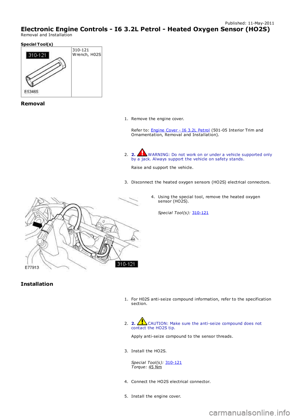
Removal Remove t he engi ne cover.
Refer t o: Engi ne Cover - I6 3.2L Pet rol (501-05 Int eri or Trim and
Ornament ati on, Removal and Ins tal lat ion).
1.
2. W ARNING: Do not work on or under a vehi cle s upported onl y
by a jack. Al ways support t he vehi cl e on s afet y s tands .
Rais e and s upport t he vehi cl e.
2.
Di sconnect t he heat ed oxygen s ens ors (HO2S) el ect ri cal connectors .
3. Us ing t he s peci al t ool, remove the heated oxygen
s ensor (HO2S).
Speci al Tool (s ): 310-121 4.
Installation For H02S ant i-s eize compound i nformati on, refer t o the specificati on
s ect ion.
1.
2. CAUTION: Make s ure the ant i-sei ze compound does not
cont act the HO2S ti p.
Apply ant i-sei ze compound t o t he s ens or threads .
2.
Inst all t he HO2S.
Speci al Tool (s ): 310-121 T orque:
45 Nm 3.
Connect t he HO2S electrical connect or.
4.
Inst all t he engi ne cover.
5.
Page 1228 of 3229
Publi s hed: 11-May-2011
Electronic Engine Controls - I6 3.2L Petrol - Catalyst Monitor Sensor
Removal and Inst all ati on
Special T ool(s) 310-121
W rench, H02S
Removal 1. W ARNING: Make sure t o s upport the vehicle wit h axle
s tands .
Rais e t he vehicle on a li ft .
1.
T orque: 6 Nm 2.
T orque: 45 Nm Speci al Tool (s ):
310-121 3.
Installation To i nst all , revers e t he removal procedure.
1.
2. NOTE: For NAS vehicl es onl y.
If required, carry out a l ong drive cycl e.
Refer t o: Powertrain Cont rol Modul e (PCM) Long Drive Cycle Sel f-Tes t
(303-14A, General Procedures ).
2.
Page 1229 of 3229
Publi s hed: 11-May-2011
Electronic Engine Controls - I6 3.2L Petrol - Mass Air Flow (MAF) Sensor
Removal and Inst all ati on
Removal T orque:
2 Nm 1.
Installation To i nst all , revers e t he removal procedure.
1.
2. NOTE: For NAS vehicl es onl y.
If required, carry out a s hort dri ve cycle.
Refer t o: Powertrain Cont rol Modul e (PCM) Short Dri ve Cycl e
Self-Tes t (303-14A, General Procedures ).
2.