2006 LAND ROVER FRELANDER 2 sensor
[x] Cancel search: sensorPage 947 of 3229
Publi s hed: 11-May-2011
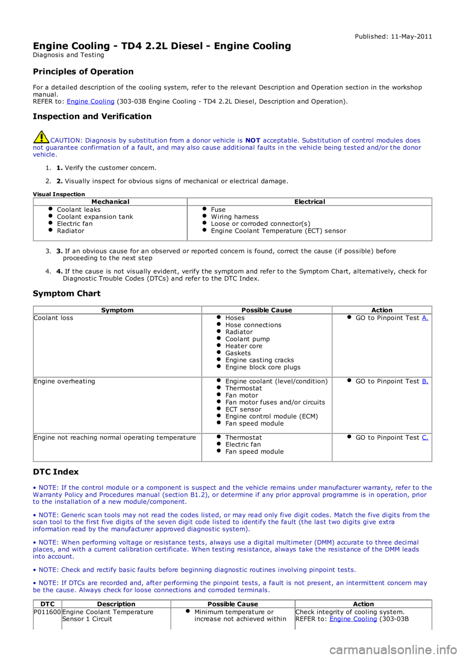
Engine Cooling - TD4 2.2L Diesel - Engine Cooling
Diagnosi s and Tes ti ng
Principles of Operation
For a detail ed descripti on of the cooli ng s ys t em, refer t o t he rel evant Des cript ion and Operat ion secti on in the workshop
manual.
REFER to: Engine Cooli ng (303-03B Engi ne Cool ing - TD4 2.2L Dies el, Des cript ion and Operat ion).
Inspection and Verification CAUTION: Di agnos is by s ubs ti tut ion from a donor vehicle is
NO T acceptabl e. Subs ti tut ion of cont rol modules does
not guarant ee confirmat ion of a faul t, and may als o caus e addit ional fault s i n t he v ehi cl e being t est ed and/or t he donor
vehi cl e.
1. Verify t he cus t omer concern.
1.
2. Vis ually ins pect for obvious s igns of mechani cal or electrical damage.
2.
Visual Inspection Mechanical Electrical
Coolant leaks Coolant expans ion t ank
Electric fan
Radiat or Fuse
W i ri ng harness
Loos e or corroded connect or(s )
Engi ne Coolant Temperature (ECT) s ensor
3.
If an obvious cause for an obs erved or report ed concern is found, correct t he caus e (if pos s ible) before
proceeding t o t he next s t ep
3.
4. If t he caus e is not vis ually evi dent , verify t he sympt om and refer t o t he Sympt om Ch art, al ternat ively, check for
Di agnos ti c Trouble Codes (DTCs) and refer t o t he DTC Index.
4.
Symptom Chart Symptom Possible CauseAction
Coolant los s Hoses Hose connect ions
Radi ator
Cool ant pump
Heat er core
Gaskets
Engi ne cas t ing cracks
Engi ne block core plugs GO t o Pinpoint Test
A.Engine overheati ng
Engi ne cool ant (level/condit ion) Thermos tat
Fan motor
Fan motor fus es and/or circui ts
ECT s ens or
Engi ne cont rol module (ECM)
Fan speed module GO t o Pinpoint Test
B.Engine not reaching normal operat ing t emperat ure
Thermos tat Elect ric fan
Fan speed module GO t o Pinpoint Test
C.DTC Index
• NOTE: If the control modul e or a component i s s us pect and the vehicle remains unde r manufacturer warrant y, refer t o the
W arranty Pol icy and Procedures manual (s ect ion B1.2), or determine i f any pri or appr oval programme is in operat ion, pri or
t o the ins tall ati on of a new module/component.
• NOTE: Generic scan t ool s may not read the codes li st ed, or may read only fi ve digi t codes . Mat ch the five di git s from t he
s can tool to the firs t fi ve di git s of the seven digi t code l is ted to ident ify t he fa ul t (t he las t t wo digi ts gi ve ext ra
informat ion read by the manufact urer approved diagnos t ic s ys tem).
• NOTE: W hen performing volt age or res is t ance t est s , always use a digi tal mult imeter (DMM) accurat e t o t hree deci mal
places, and wi th a current cali brati on cert ifi cat e. W hen t est ing res is tance, al ways take t he res is t ance of t he DMM leads
int o account.
• NOTE: Check and recti fy bas ic faul ts before beginni ng diagnos t ic rout ines i nvol vi n g pinpoint t es t s.
• NOTE: If DTCs are recorded and, aft er performi ng the pi npoi nt tes ts , a fault is no t present , an int ermi tt ent concern may
be t he caus e. Always check for loose connect ions and corroded terminals .
DT C Description Possible Cause Action
P011600 Engine Coolant Temperat ure
Sensor 1 Circuit Mini mum temperat ure or
increas e not achi eved wi thi n Check int egrit y of cool ing s ys tem.
REFER t o: Engi ne Cool ing (303-03B
Page 948 of 3229
1
2
1
1
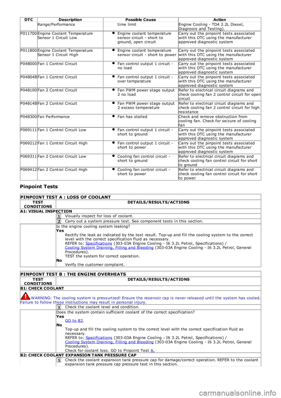
DT C
Description Possible Cause Action
Range/Performance t ime limitEngine Cooli ng - TD4 2.2L Dies el,
Di agnos is and Tes t ing).
P011700 Engine Coolant Temperat ure
Sensor 1 Circuit Low Engi ne cool ant temperat ure
s ens or circuit - short to
ground, open ci rcuit Carry out t he pinpoint t es t s as sociat ed
wi th thi s DTC us ing t he manufacturer
approved diagnost ic sys tem
P011800 Engine Coolant Temperat ure
Sensor 1 Circuit Hi gh Engi ne cool ant temperat ure
s ens or circuit - short to power Carry out t he pinpoint t es t s as sociat ed
wi th thi s DTC us ing t he manufacturer
approved diagnost ic sys tem
P048000 Fan 1 Cont rol Circui t Fan cont rol output 1 circui t -
no l oad Carry out t he pinpoint t es t s as sociat ed
wi th thi s DTC us ing t he manufacturer
approved diagnost ic sys tem
P04804B Fan 1 Cont rol Circui t Fan cont rol output 1 circui t -
over t emperat ure Carry out t he pinpoint t es t s as sociat ed
wi th thi s DTC us ing t he manufacturer
approved diagnost ic sys tem
P048100 Fan 2 Cont rol Circui t Fan PW M power s t age out put
2 no l oad Refer t o el ect ri cal circui t di agrams and
check cooli ng fan 2 cont rol circui t for open
circui t
P04814B Fan 2 Cont rol Circui t Fan PW M power s t age out put
2 exces s t emperat ure Refer t o el ect ri cal circui t di agrams and
check cooli ng fan 2 cont rol circui t for high
resi s tance
P048300 Fan Performance Fan has s tall ed Check and remove obs truct ion from
cooli ng fan. Check for sei zure of cool ing
fan
P069111 Fan 1 Cont rol Circui t Low Fan cont rol output 1 circui t -
s hort t o ground Carry out t he pinpoint t es t s as sociat ed
wi th thi s DTC us ing t he manufacturer
approved diagnost ic sys tem
P069212 Fan 1 Cont rol Circui t High Fan cont rol output 1 circui t -
s hort t o power Carry out t he pinpoint t es t s as sociat ed
wi th thi s DTC us ing t he manufacturer
approved diagnost ic sys tem
P069311 Fan 2 Cont rol Circui t Low Cooling fan control circui t -
s hort t o ground Refer t o el ect ri cal circui t di agrams and
check cooli ng fan cont rol ci rcuit for short
t o ground
P069412 Fan 2 Cont rol Circui t High Cooling fan control circui t -
s hort t o power Refer t o el ect ri cal circui t di agrams and
check cooli ng fan cont rol ci rcuit for short
t o power
Pinpoint Tests
PINPOINT TEST A : LOSS OF COOLANT T EST
CO NDIT IONS DET AILS/RESULT S/ACT IONS
A1: VISUAL INSPECT ION Vis ually ins pect for l oss of coolant .
Carry out a s ys t em press ure tes t. See component t es ts i n t his s ecti on.
Is the engine cooli ng sys t em l eaking?
Yes
Rect ify t he leak as i ndi cat ed by t he tes t res ult . Top-up and fil l t he cooling sys tem t o the correct
level wit h t he correct s pecificati on fl uid as necess ary.
REFER to: Speci fi cat ions (303-03A Engi ne Cool ing - I6 3.2L Petrol , Specificati ons) /
Cool ing Sys tem Drai ning, Fi ll ing and Bl eeding (303-03A Engine Cooli ng - I6 3.2L Pet rol, General
Procedures).
TEST the s ys tem for correct operat ion.
No Veri fy t he cust omer compl aint.
PINPOINT TEST B : THE ENGINE OVERHEATS T EST
CONDIT IONS DET AILS/RESULT S/ACT IO NS
B1: CHECK CO OLANT W ARNING: The cool ing s yst em is pres s uri zed! Ensure t he res ervoir cap i s never rel eas
ed unt il t he sys t em has cool ed.
Fail ure t o fol low thes e ins t ructi ons may res ult i n pers onal i njury.
Check t he cool ant l evel and condi ti on.
Does the s ys tem cont ai n s ufficient cool ant of t he correct s peci fi cat ion?
Yes GO t o B2 .
No Top-up and fi ll t he cool ing s ys tem to the correct l evel wi th the correct s pecifi cat i on flui d as
neces sary.
REFER t o: Speci ficat ions (303-03A Engi ne Cool ing - I6 3.2L Pet rol , Specificati ons ) /
Cool ing Sys tem Drai ni ng, Fi lli ng and Bleeding (303-03A Engine Cooli ng - I6 3.2L Pet rol, General
Procedures ).
Check for coolant los s . GO t o Pi npoint Tes t A.B2: CHECK CO OLANT EXPANSION T ANK PRESSURE CAP
Check t he cool ant expansi on tank press ure cap for damage/correct operati on. REFER t o t he cool ant
expans ion t ank pres sure cap pres sure t est i n t his s ect ion.
Page 978 of 3229
Publi s hed: 11-May-2011
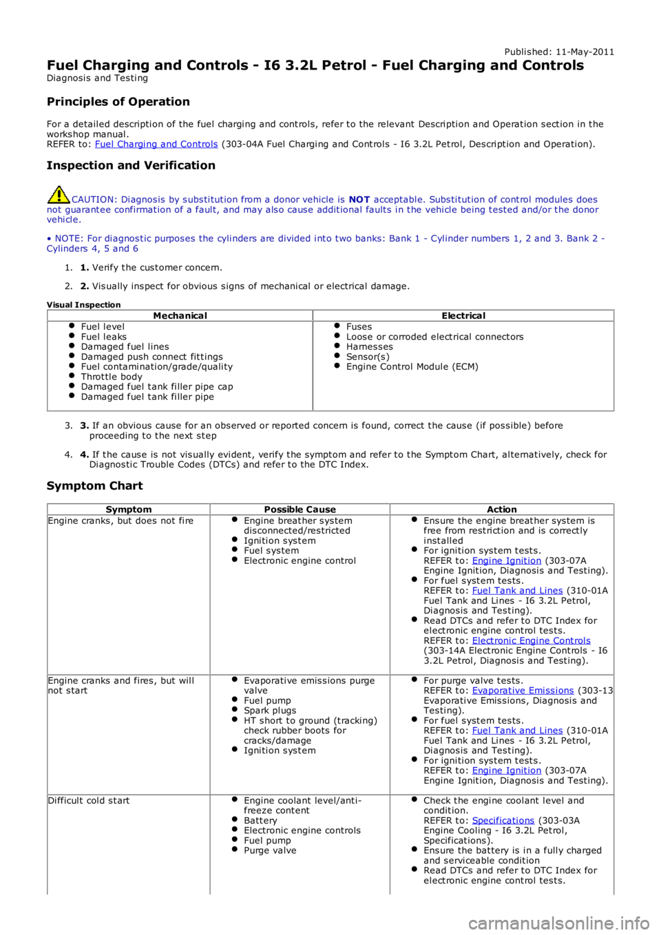
Fuel Charging and Controls - I6 3.2L Petrol - Fuel Charging and Controls
Diagnosi s and Tes ti ng
Principles of Operation
For a detail ed descripti on of the fuel chargi ng and cont rol s, refer t o the relevant Descri pti on and Operat ion s ect ion in t heworks hop manual .REFER to: Fuel Chargi ng and Controls (303-04A Fuel Chargi ng and Cont rol s - I6 3.2L Pet rol, Des cri pt ion and Operati on).
Inspection and Verification
CAUTION: Di agnos is by s ubs ti tut ion from a donor vehicle is NO T acceptabl e. Subs ti tut ion of cont rol modules doesnot guarant ee confirmat ion of a faul t, and may als o caus e addit ional fault s i n t he vehi cl e being t est ed and/or t he donorvehi cl e.
• NOTE: For di agnos t ic purpos es the cyli nders are divided i nt o t wo banks: Bank 1 - Cyl inder numbers 1, 2 and 3. Bank 2 -Cylinders 4, 5 and 6
1. Verify t he cus t omer concern.1.
2. Vis ually ins pect for obvious s igns of mechani cal or electrical damage.2.
Visual Inspection
MechanicalElectricalFuel l evelFuel l eaksDamaged fuel l inesDamaged push connect fit t ingsFuel contami nati on/grade/quali tyThrot tl e bodyDamaged fuel t ank fi ller pipe capDamaged fuel t ank fi ller pipe
FusesLoos e or corroded elect rical connect orsHarnes s esSensor(s )Engine Control Modul e (ECM)
3. If an obvious cause for an obs erved or report ed concern is found, correct t he caus e (if pos s ible) beforeproceeding t o t he next s t ep3.
4. If t he caus e is not vis ually evi dent , verify t he sympt om and refer t o t he Sympt om Chart, al ternat ively, check forDi agnos ti c Trouble Codes (DTCs) and refer t o t he DTC Index.4.
Symptom Chart
SymptomPossible CauseAction
Engine cranks , but does not fi reEngine breat her s ys temdis connected/res trictedIgni ti on s ys t emFuel s ys temElectronic engine control
Ens ure the engine breat her sys tem isfree from rest ri ct ion and is correct lyi nst all edFor igni ti on sys t em t est s .REFER t o: Engi ne Ignit ion (303-07AEngine Ignit ion, Diagnosi s and Test ing).For fuel s yst em tes ts .REFER t o: Fuel Tank and Lines (310-01AFuel Tank and Li nes - I6 3.2L Petrol,Di agnos is and Tes t ing).Read DTCs and refer t o DTC Index forel ect ronic engine cont rol tes t s.REFER t o: Elect roni c Engi ne Cont rol s(303-14A Elect ronic Engine Cont rols - I63.2L Petrol , Diagnosi s and Test ing).
Engine cranks and fires , but wil lnot s tartEvaporati ve emis s ions purgevalveFuel pumpSpark pl ugsHT s hort t o ground (t racki ng)check rubber boots forcracks/damageIgni ti on s ys t em
For purge valve t es ts .REFER t o: Evaporat ive Emi ss i ons (303-13Evaporati ve Emis s ions , Diagnosi s andTes ti ng).For fuel s yst em tes ts .REFER t o: Fuel Tank and Lines (310-01AFuel Tank and Li nes - I6 3.2L Petrol,Di agnos is and Tes t ing).For igni ti on sys t em t est s .REFER t o: Engi ne Ignit ion (303-07AEngine Ignit ion, Diagnosi s and Test ing).
Di fficul t col d s t artEngine coolant level/ant i-freeze cont entBatt eryElectronic engine controlsFuel pumpPurge valve
Check t he engi ne cool ant l evel andcondit ion.REFER t o: Specificati ons (303-03AEngine Cool ing - I6 3.2L Pet rol ,Specificat ions ).Ens ure the bat tery is i n a full y chargedand s ervi ceable condit ionRead DTCs and refer t o DTC Index forel ect ronic engine cont rol tes t s.
Page 998 of 3229
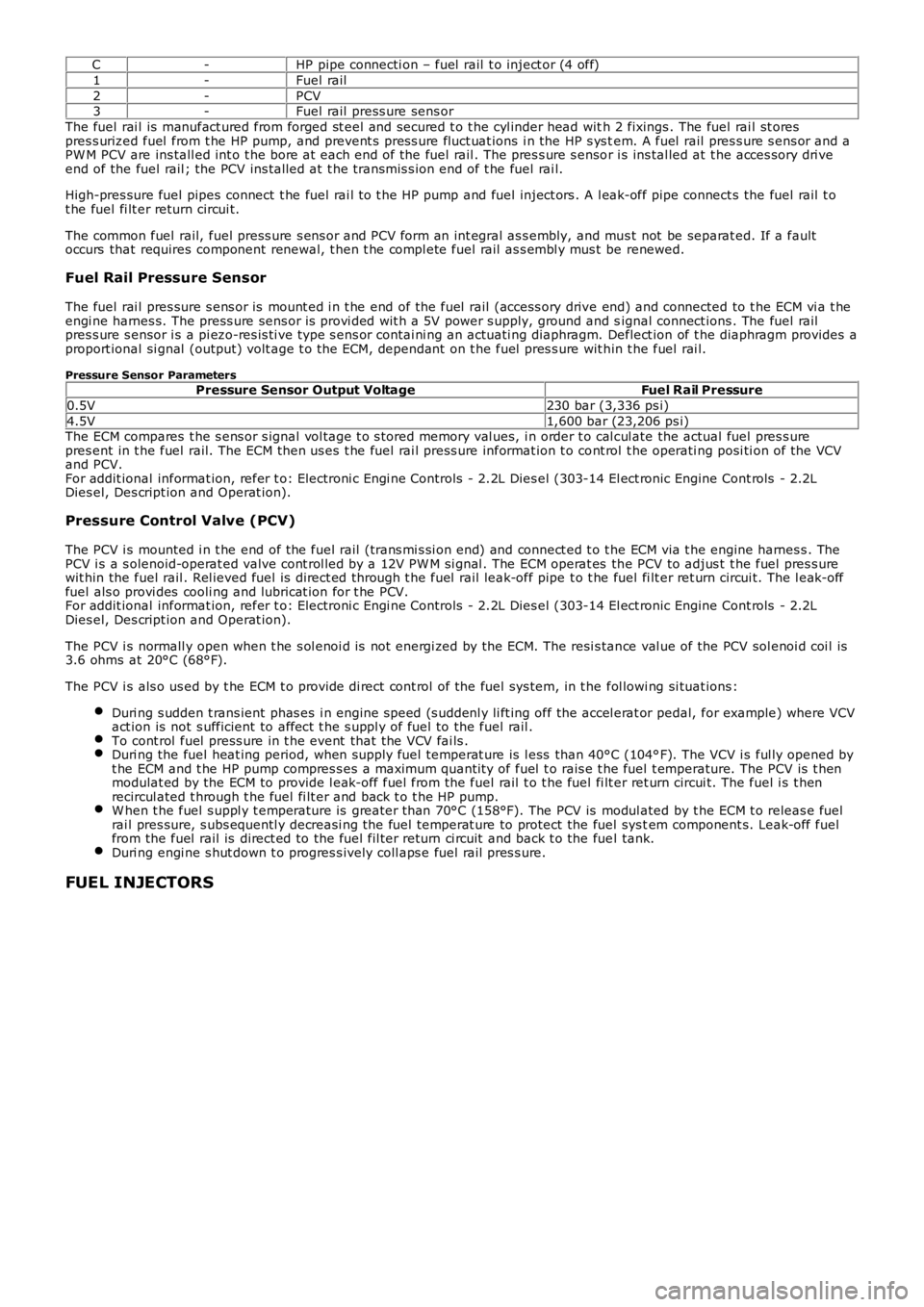
C-HP pipe connecti on – fuel rail t o inject or (4 off)
1-Fuel rail
2-PCV3-Fuel rail press ure sens or
The fuel rai l is manufact ured from forged st eel and secured t o t he cyl inder head with 2 fixings . The fuel rai l st orespres s urized fuel from t he HP pump, and prevent s pres s ure fluct uat ions i n the HP s ys tem. A fuel rail pres s ure s ens or and aPW M PCV are ins tall ed int o t he bore at each end of the fuel rail . The pres s ure s ensor i s ins tal led at t he acces sory dri veend of the fuel rail ; the PCV ins tal led at t he transmis s ion end of t he fuel rai l.
High-pres sure fuel pipes connect t he fuel rai l t o t he HP pump and fuel inject ors . A l eak-off pipe connect s the fuel rail t ot he fuel fi lt er return circui t.
The common fuel rail, fuel press ure s ens or and PCV form an int egral as s embly, and mus t not be separat ed. If a faultoccurs that requires component renewal, t hen t he compl ete fuel rail as s embl y mus t be renewed.
Fuel Rail Pressure Sensor
The fuel rai l pres sure s ens or is mount ed i n t he end of the fuel rail (access ory drive end) and connected to t he ECM vi a t heengi ne harnes s. The press ure sens or is provi ded wit h a 5V power s upply, ground and signal connect ions . The fuel railpres s ure s ensor i s a pi ezo-res is ti ve type s ens or contai ni ng an actuati ng diaphragm. Deflect ion of t he diaphragm provides aproport ional si gnal (output) volt age t o t he ECM, dependant on t he fuel pres s ure wit hin t he fuel rai l.
Pressure Sensor ParametersPressure Sensor Output VoltageFuel Rail Pressure
0.5V230 bar (3,336 ps i)
4.5V1,600 bar (23,206 ps i)The ECM compares t he s ens or s ignal vol tage t o s tored memory val ues, i n order t o cal cul ate the actual fuel pres s urepres ent in t he fuel rail. The ECM then us es t he fuel rai l press ure informat ion t o cont rol t he operati ng posi ti on of the VCVand PCV.For addit ional informat ion, refer t o: Electroni c Engi ne Controls - 2.2L Dies el (303-14 El ect ronic Engine Cont rols - 2.2LDies el, Des cript ion and Operat ion).
Pressure Control Valve (PCV)
The PCV i s mounted i n t he end of the fuel rail (trans mi s si on end) and connect ed t o the ECM via t he engine harnes s . ThePCV i s a s olenoid-operat ed valve cont rol led by a 12V PW M si gnal . The ECM operat es the PCV to adjus t t he fuel pres s urewit hin the fuel rail . Rel ieved fuel is direct ed through t he fuel rail leak-off pipe t o t he fuel fi lt er ret urn circui t. The l eak-offfuel als o provi des cooli ng and lubricat ion for t he PCV.For addit ional informat ion, refer t o: Electroni c Engi ne Controls - 2.2L Dies el (303-14 El ect ronic Engine Cont rols - 2.2LDies el, Des cript ion and Operat ion).
The PCV i s normall y open when t he s ol enoi d is not energi zed by the ECM. The resi s tance val ue of the PCV sol enoi d coi l is3.6 ohms at 20°C (68°F).
The PCV i s als o us ed by t he ECM t o provide di rect cont rol of the fuel sys tem, in t he fol lowi ng si tuat ions :
Duri ng s udden t rans ient phas es i n engine s peed (s uddenl y li ft ing off the accel erat or pedal, for example) where VCVact ion is not s ufficient to affect t he s uppl y of fuel to the fuel rail .To cont rol fuel press ure in t he event that the VCV fai ls .Duri ng the fuel heat ing period, when supply fuel temperat ure is l ess than 40°C (104°F). The VCV i s ful ly opened byt he ECM and t he HP pump compres s es a maximum quanti ty of fuel t o rais e t he fuel t emperature. The PCV is t henmodulat ed by the ECM to provide l eak-off fuel from the fuel rail t o t he fuel fi lt er ret urn circui t. The fuel i s t henrecircul ated t hrough t he fuel fi lt er and back t o t he HP pump.W hen t he fuel s uppl y t emperature is greater t han 70°C (158°F). The PCV is modul ated by t he ECM t o releas e fuelrai l pres sure, s ubs equentl y decreasi ng the fuel temperat ure to protect the fuel sys tem component s. Leak-off fuelfrom the fuel rail is direct ed to the fuel fil ter return ci rcuit and back t o the fuel tank.Duri ng engi ne s hut down t o progres s ively coll aps e fuel rail pres s ure.
FUEL INJECTORS
Page 1027 of 3229
At low engi ne s peed t he volume of exhaust gas l eavi ng the engine is l ow. The vanes are moved toward the cl osed pos it iont o direct t he exhaus t gas fl ow t o t he out s ide edge of t he turbine wheel. The clos ed posi ti on of the vanes creates ares t ri ct ion t o t he gas fl ow and i ncreas es t he gas vel oci ty to the t urbine wheel . The turbi ne wheel s peed is increas ed,cons equent ly producing more charge ai r (boos t pres sure) from t he compres sor.
B - Moderate Engine Speed
As engine s peed and exhaus t gas vol ume increas e, the vanes are moved to the open posit ion t o direct t he exhaus t gasfl ow t oward t he center of the turbi ne wheel . The vanes do not rest ri ct the exhaus t gas flow and therefore exhaus t gasveloci ty is dependant on engine s peed. The t urbi ne wheel s peed is maintai ned due to the i ncreas ed velocit y of t he gas esleaving t he engine and being di rected t oward the center area of t he t urbine wheel .
C - Maximum Engine Speed
At maximum engine s peed the volume of exhaus t gas leavi ng t he engi ne is hi gh. The vanes are moved toward the full yopen pos i ti on and do not affect t he gas vel oci ty. The exhaus t gas fl ow contacts t he center area of t he t urbine wheel tomaint ain t he t urbine wheel s peed and boos t pres s ure from the compress or.
Over-Boost Pressure
Duri ng periods of medi um t o hard accelerat ion, the turbocharger is requi red t o produce a l imit ed period of over-boos tpres s ure from the compress or to meet the current engi ne fueli ng requirement. The ECM wil l reques t and all ow t he REA t omove t he variable vanes t oward t he clos ed posi ti on t o increas e t he vel oci ty of t he already high-s peed turbine wheel. Theover-boos t condit ion is all owed by t he ECM for t he l imi ted period.
Barometric Pressure Sensor
At high al ti tude t he t urbocharger wi ll functi on normal ly, but due t o t he l ower ambi ent ai r pres sure t he turbi ne andcompres sor may tend t o over-speed. A baromet ri c pres sure s ensor i s located i n t he ECM t o prevent over-boost andposs i bl e engine damage occurri ng under t hes e condit ions. The ECM opens t he vari abl e vanes earlier duri ng t he openi ngphas e to s uit the al ti tude of t he vehi cl e.
T urbocharger Lubrication
The rapi d accelerat ion and decelerat ion demands of t he turbocharger rel y on a s t eady flow of cl ean oil. The oi l suppli ed byt he engi ne lubri cat ion s ys tem provides l ubricati on to the t urbocharger shaft and bearings, whi le al so act ing as a cool antfor t he t urbocharger cent er hous i ng.
To mai nt ain the l ife expect ancy of t he turbocharger, t he engine oil mus t be replenished at regular s ervice i nt ervals wit ht he recommended qual it y and quant it y of oil . The oi l mus t have a free-fl ow t hrough the turbocharger and an unres trict edret urn to t he engine oi l pan.
Page 1106 of 3229
CAUTION: To avoid damage/malfuncti oni ng of the BMS module, always us e a s uit able body ground point rather thant he bat t ery negat ive terminal when connect ing a s lave power supply.
For addit ional informat ion, refer t o: Batt ery (414-01 Bat tery, Mounti ng and Cables , Diagnos is and Tes t ing).
Gear Neutral Sensor
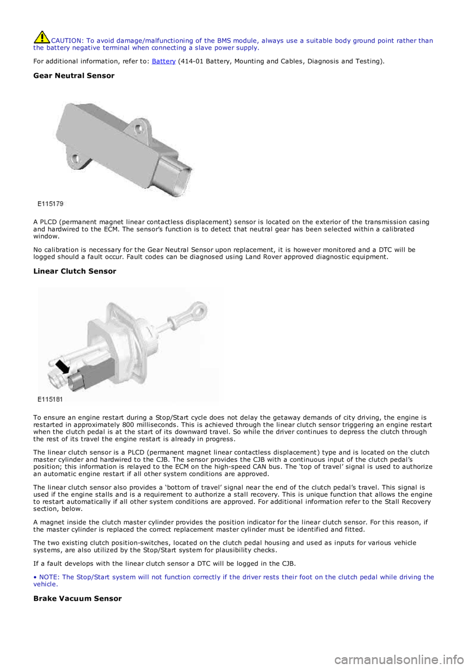
A PLCD (permanent magnet l inear cont act les s dis placement) s ensor i s located on the exterior of the trans mi s si on cas i ngand hardwired t o t he ECM. The sens or’s functi on is t o det ect t hat neut ral gear has been s elected wi thi n a cali bratedwindow.
No cali brati on is neces sary for t he Gear Neut ral Sensor upon repl acement, i t is however monit ored and a DTC wil l belogged s houl d a fault occur. Fault codes can be diagnos ed us ing Land Rover approved di agnos ti c equi pment.
Linear Clutch Sensor
To ens ure an engine res tart during a St op/St art cycl e does not del ay the get away demands of cit y dri ving, the engine i sres t art ed in approximately 800 mil li seconds . This i s achi eved through t he li near clut ch s ens or triggeri ng an engine rest artwhen t he cl utch pedal is at t he s tart of i ts downward t ravel. So whil e t he dri ver conti nues t o depres s t he clutch t hrought he res t of it s t ravel t he engine rest art i s already i n progress .
The li near clut ch s ens or is a PLCD (permanent magnet li near contactl es s di spl acement) type and i s located on t he clut chmas ter cylinder and hardwired t o t he CJB. The s ensor provi des t he CJB wi th a cont inuous input of the clut ch pedal ’sposi ti on; this informati on is relayed t o t he ECM on t he high-speed CAN bus . The ‘t op of travel ’ si gnal i s used to aut horizean automat ic engine res tart if all ot her s ys tem condit ions are approved.
The li near clut ch s ens or als o provides a ‘bott om of t ravel’ s ignal near t he end of the cl ut ch pedal ’s t ravel. This si gnal i sus ed if t he engi ne s tal ls and i s a requi rement t o authori ze a s tal l recovery. This is unique funct ion t hat allows the enginet o res t art automat ically if all ot her s ys tem condit ions are approved. For addi ti onal i nformat ion refer t o t he Stall Recoverys ect ion, below.
A magnet ins ide the clut ch mas ter cylinder provides t he posi ti on indicator for the linear cl utch s ensor. For t his reason, ift he mas ter cyl inder is replaced the correct replacement mas t er cyli nder mus t be i dent ified and fit t ed.
The t wo exis ti ng clutch pos it ion-s wi tches, l ocat ed on t he cl utch pedal hous ing and us ed as i nput s for vari ous vehi cl es ys t ems , are al so ut il ized by t he Stop/Start sys tem for pl aus ibi lit y checks .
If a fault develops wi th the l inear cl utch s ensor a DTC wil l be logged in the CJB.
• NOTE: The Stop/Start sys tem wil l not funct ion correctl y if t he dri ver rest s t hei r foot on t he clut ch pedal whil e dri vi ng t hevehi cl e.
Brake Vacuum Sensor
Page 1136 of 3229
Publi s hed: 11-May-2011
Engine Emission Control - TD4 2.2L Diesel - Engine Emission Control
Diagnosi s and Tes ti ng
Principles of Operation
For a detail ed descripti on of the engine emis s ion control s ys tems , refer to the relevant Des cri pt ion and Operati on s ect ionin the workshop manual.REFER to: Engine Emi s si on Cont rol (303-08B Engine Emi ss i on Cont rol - TD4 2.2L Dies el, Des cript ion and Operat ion).
Inspection and Verification
CAUTION: Di agnos is by s ubs ti tut ion from a donor vehicle is NO T acceptabl e. Subs ti tut ion of cont rol modules doesnot guarant ee confirmat ion of a faul t, and may als o caus e addit ional fault s i n t he vehi cl e being t est ed and/or t he donorvehi cl e.
1. Verify t he cus t omer concern.1.
2. Vis ually ins pect for obvious s igns of mechani cal or electrical damage.2.
Visual InspectionMechanicalElectrical
EGR valveEGR pi pes /hos esVacuum s ys t emEngine breat her s ys tem
W i ring harnes sElect rical connect or(s)Fus es (s )
3. If an obvious cause for an obs erved or report ed concern is found, correct t he caus e (if pos s ible) beforeproceeding t o t he next s t ep3.
4. If t he caus e is not vis ually evi dent , verify t he sympt om and refer t o t he Sympt om Chart, al ternat ively, check forDi agnos ti c Trouble Codes (DTCs) and refer t o t he DTC Index.4.
Symptom Chart
SymptomPossible CauseActionRough idl e, l ack of power under accel erati on,exces s ive fuel consumpt ion, exces s ive blacks moke
EGR valve s t uckCheck EGR valve for correct operati on.Check for relat ed DTCs and refer t o t he DTCIndex
Exces s ive engine bl ow-by/crankcas e press ureEngine breat her s ys temblocked/res trict edExces s ive engine wear
Check engine breat her s ys tem forbl ockage/res t ri ct ion. Check for exces si veengine wearREFER t o: Engi ne (303-00 Engi ne Sys t em -General Informati on, Di agnos is andTes t ing).
DTC Index
• NOTE: If the control modul e or a component i s s us pect and the vehicle remains under manufacturer warrant y, refer t o theW arranty Pol icy and Procedures manual (s ect ion B1.2), or determine i f any pri or approval programme is in operat ion, pri ort o the ins tall ati on of a new module/component.
• NOTE: Generic scan t ool s may not read the codes li st ed, or may read only fi ve digit codes . Mat ch the five di git s from t hes can tool to the firs t fi ve di git s of the seven digi t code l is ted to ident ify t he faul t (t he las t t wo digi ts gi ve addi ti onalinformat ion read by the manufact urer approved diagnos t ic s ys tem).
• NOTE: W hen performing volt age or res is t ance t est s , always use a digi tal mult imeter (DMM) accurat e t o t hree deci malplaces, and wi th an up-t o-date cal ibrat ion cert ificate. W hen tes ti ng res is t ance al ways take t he res is t ance of t he DMMleads i nt o account .
• NOTE: Check and recti fy bas ic faul ts before beginni ng diagnos t ic rout ines i nvol vi ng pinpoint t es t s.
• NOTE: Ins pect connect ors for s igns of water ingres s , and pins for damage and/or corros ion.
• NOTE: If DTCs are recorded and, aft er performi ng the pi npoi nt tes ts , a fault is not present , an int ermi tt ent concern maybe t he caus e. Always check for loose connect ions and corroded terminals .
DT CDescriptionPossible CauseAction
P040500Exhaus t Gas Recirculat ionSensor A Circuit LowEGR Valve pos it ion s ensorvol tage below lower li mitCarry out t he pinpoint t est s as sociat ed wit hthis DTC usi ng t he manufacturer approveddi agnos ti c s yst emP040600Exhaus t Gas Recirculat ionSensor A Circuit Hi ghEGR Valve pos it ion s ensorvol tage above upper l imi tCarry out t he pinpoint t est s as sociat ed wit hthis DTC usi ng t he manufacturer approveddi agnos ti c s yst em
P042E00Exhaus t Gas Recirculat ionControl St uck OpenEGR Valve s tuck duri ng normalengi ne running - at tempt t ouns t ick valve unsucces s ful
Check/clear EGR valve fromobs t ructi on/s ti cking
Page 1173 of 3229
DT CDescriptionPossible CausesAction
sys t em
P007200Ambi ent Ai r TemperatureSensor Ci rcuit LowAmbi ent ai r temperature s ens or ci rcuit -s hort t o ground, open circuitCarry out t he pinpoint t est sass ociated wit h t hi s DTC us ing t hemanufact urer approved diagnost icsys t em
P007300Ambi ent Ai r TemperatureSensor Ci rcuit HighAmbi ent ai r temperature s ens or ci rcuit -s hort t o powerCarry out t he pinpoint t est sass ociated wit h t hi s DTC us ing t hemanufact urer approved diagnost icsys t em
P009700Intake Air Temperat ureSensor 2 Ci rcuit LowIntake ai r temperat ure sens or vol tagebel ow lower l imi tCarry out t he pinpoint t est sass ociated wit h t hi s DTC us ing t hemanufact urer approved diagnost icsys t emP009800Intake Air Temperat ureSensor 2 Ci rcuit Hi ghIntake ai r temperat ure sens or vol tageabove upper l imi tCarry out t he pinpoint t est sass ociated wit h t hi s DTC us ing t hemanufact urer approved diagnost icsys t emP010000Mas s or Volume Ai r Flow ACircui tMAF Sens or s ignal circui t - s hort t oground, power, open circui tCarry out t he pinpoint t est sass ociated wit h t hi s DTC us ing t hemanufact urer approved diagnost icsys t em
P010221Mas s or Volume Ai r Flow ACircui t LowAi r fl ow PW M raw s ignal above upperl imitCarry out t he pinpoint t est sass ociated wit h t hi s DTC us ing t hemanufact urer approved diagnost icsys t em
P010226Mas s or Volume Ai r Flow ACircui t LowAi r fl ow PW M correct ed si gnal aboveupper li mitCarry out t he pinpoint t est sass ociated wit h t hi s DTC us ing t hemanufact urer approved diagnost icsys t em
P010322Mas s or Volume Ai r Flow ACircui t HighAi r fl ow PW M raw s ignal above upperl imitCarry out t he pinpoint t est sass ociated wit h t hi s DTC us ing t hemanufact urer approved diagnost icsys t em
P010327Mas s or Volume Ai r Flow ACircui t HighAi r fl ow PW M correct ed si gnal aboveupper li mitCarry out t he pinpoint t est sass ociated wit h t hi s DTC us ing t hemanufact urer approved diagnost icsys t emP011200Intake Air Temperat ureSensor 1 Ci rcuit LowIntake ai r temperat ure sens or 1 circuit -s hort t o groundCarry out t he pinpoint t est sass ociated wit h t hi s DTC us ing t hemanufact urer approved diagnost icsys t emP110222Mas s Air Fl ow Sens or inRange But Lower ThanExpect ed
Ai r Mass (meas ured) is too l ow (notpl aus i bl e) wit h calculated reference ai rmass during overrun: rati o ofcalculat ed/act ual too hi gh
Carry out t he pinpoint t est sass ociated wit h t hi s DTC us ing t hemanufact urer approved diagnost icsys t em
P110321Mas s Air Fl ow Sens or inRange But Higher ThanExpect ed
Ai r Mass (meas ured) is too hi gh (notpl aus i bl e) wit h calculated reference ai rmass during overrun: rati o ofcalculat ed/act ual too l ow
Carry out t he pinpoint t est sass ociated wit h t hi s DTC us ing t hemanufact urer approved diagnost icsys t em
P222700Baromet ri c Pres s ure Ci rcuitRange/PerformanceAt mos pheric Press ure Sens or defect iveIns tal l a new module, refer to thenew module/component ins tall ati onnot e at t he t op of the DTC Index.REFER t o: Powert rain Cont rol Module(PCM) (303-14, Removal andIns tal lat ion).