2006 LAND ROVER FRELANDER 2 sensor
[x] Cancel search: sensorPage 277 of 3229
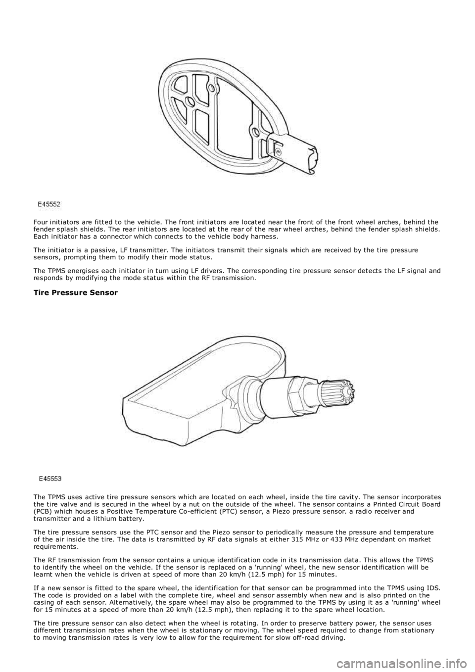
Four i nit iators are fi tt ed t o the vehicl e. The front i ni ti ators are l ocat ed near t he front of the front wheel arches , behind t hefender s pl ash shi elds . The rear init iat ors are located at t he rear of t he rear wheel arches , behind t he fender spl ash shi el ds.Each init iat or has a connect or which connects to the vehicle body harnes s .
The ini ti at or is a pass ive, LF t rans mit ter. The init iat ors t rans mi t their s ignals which are recei ved by the ti re press ures ens ors , prompt ing them to modi fy their mode st atus .
The TPMS energis es each init iat or in t urn usi ng LF dri vers. The corres ponding t ire pres s ure sens or det ect s t he LF s ignal andres ponds by modifyi ng the mode s tat us wit hin t he RF t rans mis s ion.
Tire Pressure Sensor
The TPMS us es act ive t ire pres s ure s ens ors whi ch are l ocat ed on each wheel , ins ide the ti re cavit y. The sens or incorporat est he ti re val ve and is s ecured in the wheel by a nut on t he outs i de of the wheel. The s ensor contains a Pri nt ed Ci rcuit Board(PCB) whi ch hous es a Pos it ive Temperat ure Co-efficient (PTC) s ens or, a Piezo pres s ure s ens or. a radi o receiver andt ransmit ter and a l it hium bat t ery.
The t ire pres sure s ensors use the PTC sens or and the Pi ezo sens or to periodically measure t he pres sure and t emperatureof the ai r ins ide t he t ire. The dat a is trans mi tt ed by RF dat a s ignals at ei ther 315 MHz or 433 MHz dependant on marketrequirements .
The RF t rans mis s ion from t he sens or cont ai ns a unique i dent ificati on code in i ts trans mi ss i on dat a. This all ows t he TPMSt o identi fy the wheel on t he vehi cl e. If t he s ens or is replaced on a 'running' wheel, t he new s ens or i dent ificati on wil l belearnt when the vehicle is driven at s peed of more t han 20 km/h (12.5 mph) for 15 minutes .
If a new s ensor i s fi tt ed t o t he spare wheel, t he identi fi cat ion for that s ens or can be programmed int o t he TPMS usi ng IDS.The code is provi ded on a l abel wit h t he complet e ti re, wheel and sens or ass embly when new and is al s o pri nted on t hecas i ng of each s ensor. Alt ernati vel y, t he s pare wheel may al so be programmed to the TPMS by us i ng it as a 'running' wheelfor 15 minutes at a speed of more t han 20 km/h (12.5 mph), t hen replacing it t o t he spare wheel l ocat ion.
The t ire pres sure s ensor can als o det ect when t he wheel i s rot ati ng. In order t o preserve bat t ery power, t he s ens or us esdifferent t rans mis s ion rates when the wheel is st ati onary or moving. The wheel s peed required to change from st ati onaryt o moving t rans mis s ion rates is very low t o al low for the requi rement for sl ow off-road dri ving.
Page 282 of 3229
DT CDescriptionPossible CauseAction
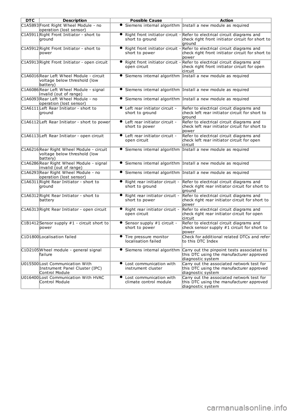
C1A5893Front Ri ght W heel Module - nooperat ion (los t s ens or)Siemens i nternal algori thmIns tal l a new module as required
C1A5911Ri ght Front Init iat or - short togroundRight front ini ti at or ci rcuit -s hort t o groundRefer to el ect ri cal circui t diagrams andcheck ri ght front i ni ti ator circui t for s hort t oground
C1A5912Ri ght Front Init iat or - short topowerRight front ini ti at or ci rcuit -s hort t o powerRefer to el ect ri cal circui t diagrams andcheck ri ght front i ni ti ator circui t for s hort t opower
C1A5913Ri ght Front Init iat or - open ci rcuitRight front ini ti at or ci rcuit -open circuitRefer to el ect ri cal circui t diagrams andcheck ri ght front i ni ti ator circui t for openci rcuitC1A6016Rear Left W heel Module - circui tvolt age below t hres hold (lowbat tery)
Siemens i nternal algori thmIns tal l a new module as required
C1A6086Rear Left W heel Module - s i gnali nval id (out of range)Siemens i nternal algori thmIns tal l a new module as required
C1A6093Rear Left W heel Module - nooperat ion (los t s ens or)Siemens i nternal algori thmIns tal l a new module as required
C1A6111Left Rear Init iator - s hort t ogroundLeft rear i nit iator circui t -s hort t o groundRefer to el ect ri cal circui t diagrams andcheck left rear init iat or ci rcuit for short toground
C1A6112Left Rear Init iator - s hort t o powerLeft rear i nit iator circui t -s hort t o powerRefer to el ect ri cal circui t diagrams andcheck left rear init iat or ci rcuit for short topower
C1A6113Left Rear Init iator - open circui tLeft rear i nit iator circui t -open circuitRefer to el ect ri cal circui t diagrams andcheck left rear init iat or ci rcuit for openci rcuitC1A6216Rear Right W heel Modul e - circui tvolt age below t hres hold (lowbat tery)
Siemens i nternal algori thmIns tal l a new module as required
C1A6286Rear Right W heel Modul e - s ignali nval id (out of range)Siemens i nternal algori thmIns tal l a new module as required
C1A6293Rear Right W heel Modul e - nooperat ion (los t s ens or)Siemens i nternal algori thmIns tal l a new module as required
C1A6311Ri ght Rear Ini ti ator - s hort t ogroundRight rear i nit iator circui t -s hort t o groundRefer to el ect ri cal circui t diagrams andcheck ri ght rear init iat or ci rcuit for s hort t oground
C1A6312Ri ght Rear Ini ti ator - s hort t obat teryRight rear i nit iator circui t -s hort t o powerRefer to el ect ri cal circui t diagrams andcheck ri ght rear init iat or ci rcuit for s hort t opower
C1A6313Ri ght Rear Ini ti ator - open circui tRight rear i nit iator circui t -open circuitRefer to el ect ri cal circui t diagrams andcheck ri ght rear init iat or ci rcuit for openci rcuitC1B1412Sens or s upply #1 - circuit s hort t opowerSensor s uppl y #1 ci rcuit -s hort t o powerRefer to el ect ri cal circui t diagrams andcheck s ens or s upply #1 circui t for s hort t opower
C1D1800Local is ati on fai ledTire pres s ure moni torlocali sat ion fail edCheck for addit ional relat ed DTCs and referto t his DTC Index
C1D2105W heel module - general s i gnalfail ureSiemens i nternal algori thmCarry out t he pinpoint t est s as sociat ed t othis DTC usi ng t he manufacturer approveddi agnos ti c s yst em
U015500Los t Communicati on W i thIns trument Panel Clus ter (IPC)Cont rol Modul e
Lost communi cat ion wi thins t rument clus terCarry out t he as sociat ed network tes t forthis DTC usi ng t he manufacturer approveddi agnos ti c s yst em
U016400Los t Communicati on W i th HVACCont rol Modul eLost communi cat ion wi thcli mate control modul eCarry out t he as sociat ed network tes t forthis DTC usi ng t he manufacturer approveddi agnos ti c s yst em
Page 284 of 3229
Publi s hed: 11-May-2011
Wheels and Tires - Tire Low Pressure Sensor
Removal and Inst all ati on
Removal
W ARNING: The val ve seal and s teel was her mus t be replaced each t ime a t ire is changed to avoi d s eal failure. Thes eal and was her must be replaced if t he s ensor i s removed. Removal of the sens or retai ning nut mus t be regarded ass ens or removal. The valve cap mus t always be in pl ace except when i nfl at ing, rel easing or checki ng pres s ure.
• NOTE: If the s ens or i s repl aced on a 'runni ng' wheel, t he new s ens or ident ifi cat ion will be learnt when t he vehi cl e i s fi rs tdri ven. If a new s ensor i s ins t al led t o t he s pare wheel, t he ident ifi cat ion for that s ensor mus t be programmed i nto t he t irepres s ure moni toring s yst em (TPMS) module us ing Land Rover approved di agnos ti c equi pment . The ident ifi cat ion code i sprovided on a label wit h t he compl ete as s embly and i s als o print ed on t he cas ing of each s ens or.
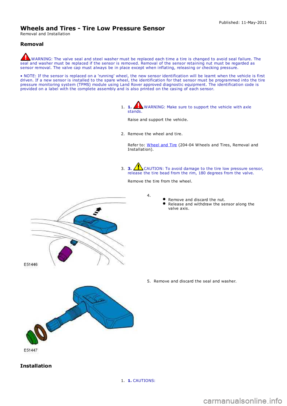
1. W ARNING: Make sure t o s upport the vehicle wit h axles tands .
Rais e and s upport t he vehi cl e.
1.
Remove t he wheel and t ire.
Refer t o: W heel and Ti re (204-04 W heel s and Tires, Removal andInst all at ion).
2.
3. CAUTION: To avoid damage t o t he t ire low pres sure s ens or,rel ease the t ire bead from the rim, 180 degrees from t he val ve.
Remove t he ti re from t he wheel.
3.
Remove and dis card t he nut.Releas e and wi thdraw the s ens or al ong thevalve axis .
4.
Remove and dis card t he s eal and was her.5.
Installation
1. CAUTIONS:1.
Page 291 of 3229
Publi s hed: 11-May-2011
Vehicle Dynamic Suspension - Rear Suspension Height Sensor
Removal and Inst all ati on
Removal
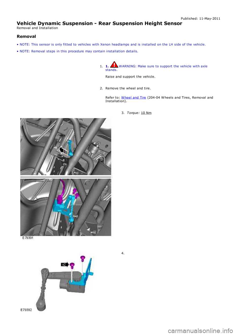
• NOTE: This s ens or i s only fit ted to vehicles wit h Xenon headlamps and is i nst all ed on the LH s ide of t he vehi cl e.
• NOTE: Removal s t eps in t his procedure may cont ain i nst all ati on det ail s.
1. W ARNING: Make sure t o s upport the vehicle wit h axle
s tands .
Rais e and s upport t he vehi cl e.
1.
Remove t he wheel and t ire.
Refer t o: W heel and Ti re (204-04 W heel s and Tires, Removal and
Inst all at ion).
2. T orque:
10 Nm 3.
4.
Page 498 of 3229
Publi s hed: 11-May-2011
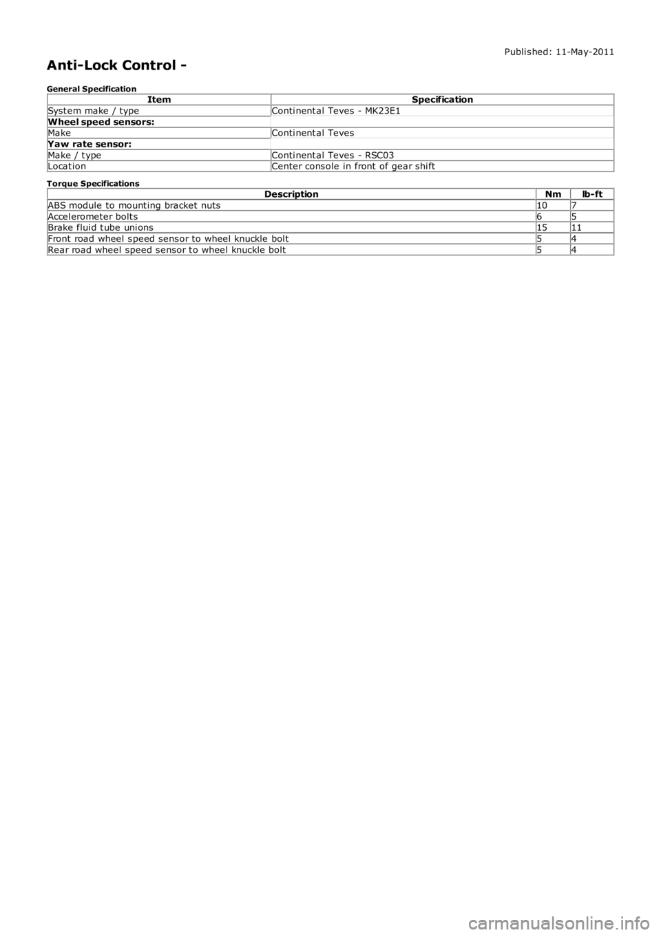
Anti-Lock Control -
General SpecificationItemSpecification
Syst em make / typeConti nent al Teves - MK23E1
Wheel speed sensors:MakeConti nent al Teves
Yaw rate sensor:
Make / t ypeConti nent al Teves - RSC03Locat ionCenter cons ole in front of gear shi ft
Torque SpecificationsDescriptionNmlb-ft
ABS module to mount ing bracket nuts107
Accel erometer bolt s65Brake flui d t ube uni ons1511
Front road wheel s peed sens or to wheel knuckle bol t54
Rear road wheel speed s ensor t o wheel knuckle bolt54
Page 506 of 3229
Publi s hed: 11-May-2011
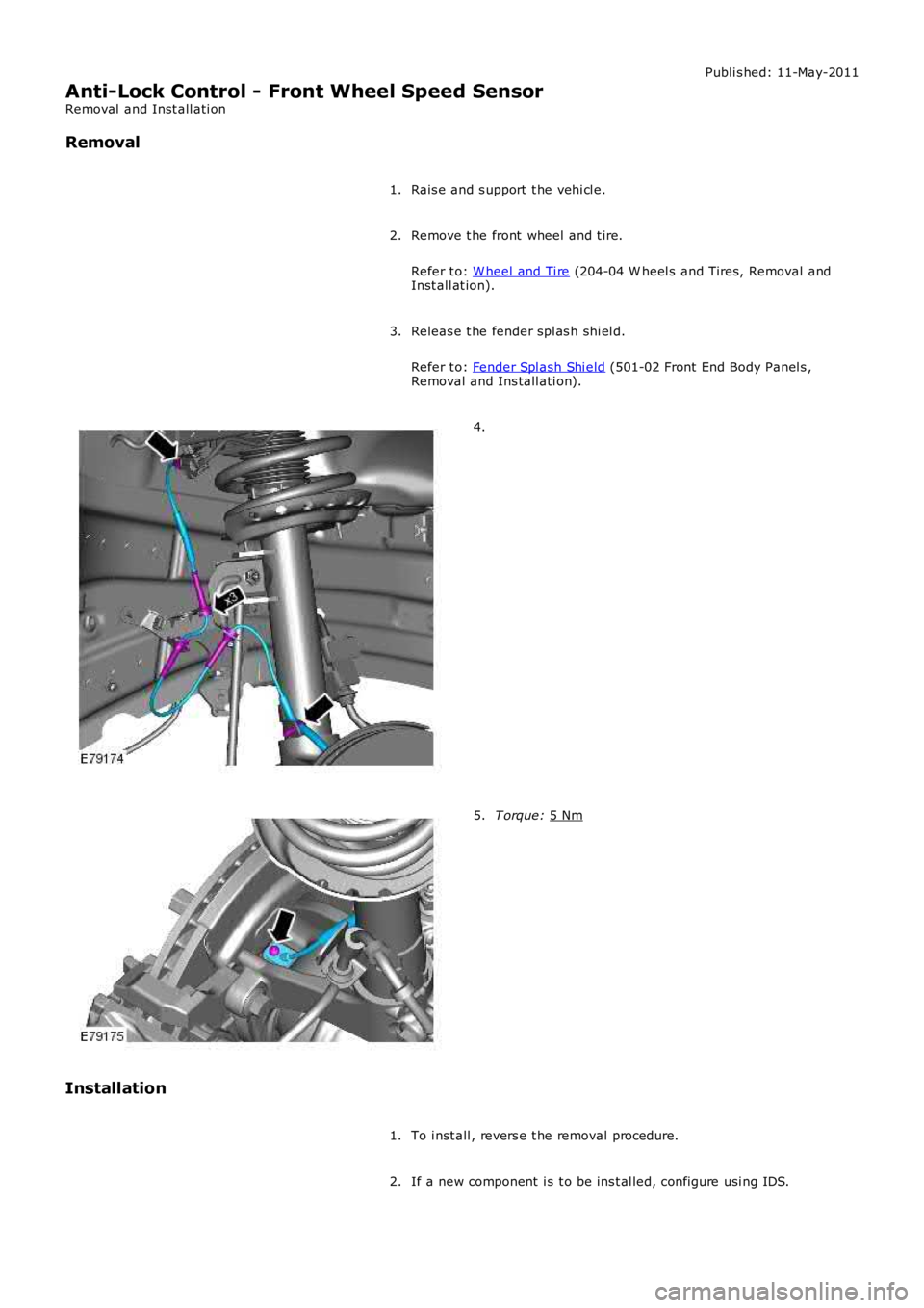
Anti-Lock Control - Front Wheel Speed Sensor
Removal and Inst all ati on
Removal
Rais e and s upport t he vehi cl e.
1.
Remove t he front wheel and t ire.
Refer t o: W heel and Ti re (204-04 W heel s and Tires, Removal and
Inst all at ion).
2.
Releas e t he fender spl as h shi el d.
Refer t o: Fender Spl ash Shi eld (501-02 Front End Body Panel s ,
Removal and Ins tall ati on).
3. 4.
T orque:
5 Nm 5.
Installation To i nst all , revers e t he removal procedure.
1.
If a new component i s t o be ins t al led, configure usi ng IDS.
2.
Page 507 of 3229
Publi s hed: 11-May-2011
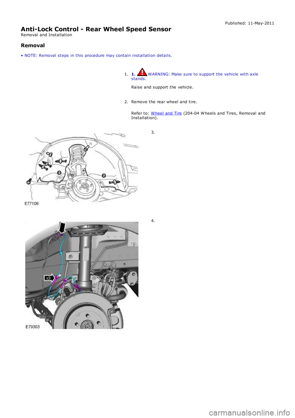
Anti-Lock Control - Rear Wheel Speed Sensor
Removal and Inst all ati on
Removal
• NOTE: Removal s t eps in t his procedure may cont ain i nst all ati on det ail s.
1. W ARNING: Make sure t o s upport the vehicle wit h axles tands .
Rais e and s upport t he vehi cl e.
1.
Remove t he rear wheel and t ire.
Refer t o: W heel and Ti re (204-04 W heel s and Tires, Removal andInst all at ion).
2.
3.
4.
Page 511 of 3229
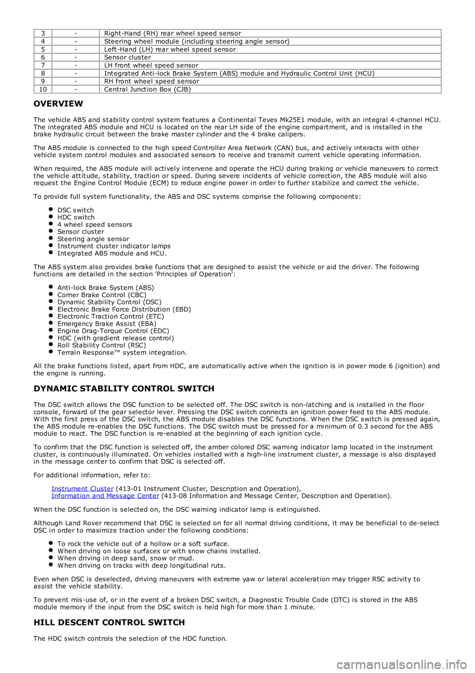
3-Right -Hand (RH) rear wheel s peed s ens or
4-Steering wheel modul e (including s t eering angle sens or)
5-Left -Hand (LH) rear wheel s peed s ens or6-Sensor clus ter
7-LH front wheel speed s ensor
8-Int egrat ed Anti -l ock Brake Sys t em (ABS) modul e and Hydrauli c Cont rol Unit (HCU)9-RH front wheel speed s ensor
10-Central Junct ion Box (CJB)
OVERVIEW
The vehi cl e ABS and s t abi li ty control sys tem feat ures a Cont inental Teves Mk25E1 module, wi th an int egral 4-channel HCU.The int egrated ABS modul e and HCU is l ocat ed on t he rear LH s ide of t he engine compart ment, and i s ins tal led i n t hebrake hydrauli c ci rcuit bet ween the brake mas ter cyl inder and the 4 brake calipers.
The ABS module is connect ed to the hi gh s peed Cont roll er Area Net work (CAN) bus , and acti vel y int eracts wi th othervehi cl e s yst em cont rol modules and as sociat ed s ens ors to recei ve and transmit current vehicle operat ing informati on.
W hen requi red, t he ABS module wi ll acti vel y int ervene and operate the HCU during braki ng or vehi cl e maneuvers t o correctt he vehi cl e att it ude, s t abi li ty, t racti on or speed. During severe incident s of vehicle correct ion, t he ABS module will al soreques t the Engine Cont rol Modul e (ECM) to reduce engi ne power i n order t o further stabil ize and correct t he vehicle.
To provide full s ys tem functi onali ty, t he ABS and DSC s ys tems compris e t he fol lowing component s :
DSC s wit chHDC s wi tch4 wheel s peed s ens orsSens or clus terSteering angle s ens orIns t rument clus ter i ndi cat or lampsInt egrat ed ABS module and HCU.
The ABS s yst em al s o provides brake funct ions t hat are des igned to ass is t t he vehi cle or aid the driver. The followi ngfuncti ons are det ai led i n t he s ect ion 'Principl es of Operati on':
Anti -l ock Brake Sys t em (ABS)Corner Brake Control (CBC)Dynamic St abi li ty Cont rol (DSC)Electroni c Brake Force Di s tributi on (EBD)Electroni c Tracti on Control (ETC)Emergency Brake As s is t (EBA)Engi ne Drag-Torque Control (EDC)HDC (wit h gradi ent releas e cont rol )Roll Stabi lit y Control (RSC)Terrai n Res pons e™ sys tem int egrati on.
All t he brake funct ions li s ted, apart from HDC, are automat icall y act ive when t he i gni ti on is in power mode 6 (igni ti on) andt he engi ne is runni ng.
DYNAMIC STABILITY CONTROL SWITCH
The DSC s wit ch all ows the DSC functi on to be s elect ed off. The DSC s wi tch i s non-latchi ng and is i nst all ed in the floorcons ole, forward of the gear s el ect or lever. Pres s ing t he DSC s wi tch connects an ignit ion power feed to t he ABS modul e.W i th the firs t pres s of the DSC swit ch, t he ABS module di sabl es the DSC funct ions . When t he DSC s wi tch i s pres sed agai n,t he ABS module re-enables t he DSC funct ions. The DSC swi tch must be press ed for a minimum of 0.3 s econd for the ABSmodule t o react . The DSC functi on is re-enabled at t he beginning of each ignit ion cycle.
To confirm that t he DSC functi on is sel ect ed off, the amber colored DSC warni ng indicator l amp located i n t he ins t rumentclus ter, is conti nuous ly i ll uminated. On vehicles i nst all ed wit h a hi gh-li ne ins t rument clus ter, a mes sage i s als o di spl ayedin the mess age cent er to confirm t hat DSC is s elect ed off.
For addit ional informat ion, refer t o:
Ins trument Clus ter (413-01 Ins t rument Clus t er, Descripti on and Operat ion),Informat ion and Mes s age Cent er (413-08 Informati on and Mes sage Cent er, Descripti on and Operat ion).
W hen t he DSC funct ion i s s elected on, t he DSC warni ng indicator l amp is ext inguis hed.
Alt hough Land Rover recommend t hat DSC is s elected on for all normal driving condit ions, i t may be benefi ci al t o de-sel ectDSC i n order t o maximi ze tract ion under t he foll owing condit ions:
To rock t he vehicle out of a holl ow or a s oft surface.W hen driving on loose s urfaces or wit h s now chains ins t al led.W hen driving i n deep s and, s now or mud.W hen driving on tracks wi th deep l ongi tudinal rut s .
Even when DSC is des elected, dri ving maneuvers wi th ext reme yaw or lateral acceleration may trigger RSC act ivit y t oas si st the vehicle st abili ty.
To prevent mis -use of, or in the event of a broken DSC s wit ch, a Diagnost ic Troubl e Code (DTC) i s s tored in the ABSmodule memory i f the input from t he DSC s wit ch is hel d high for more than 1 minut e.
HILL DESCENT CONTROL SWITCH
The HDC s wi tch control s t he s el ect ion of t he HDC funct ion.