2006 LAND ROVER FRELANDER 2 sensor
[x] Cancel search: sensorPage 512 of 3229
The HDC s wi tch i s non-lat chi ng and is ins tall ed in the floor cons ole, forward of the gear s el ect or lever. Moment aril ypres s ing and releasi ng t he HDC s wit ch connects an ignit ion power feed t o t he ABS module. W it h t he fi rs t pres s and rel easeof the HDC s wit ch, t he ABS module enables operat ion of t he HDC funct ion. W hen t he HDC swi tch i s pres s ed and rel eas edagai n, the ABS modul e dis ables operat ion of t he HDC funct ion.
To prevent mis -use of, or in the event of a broken HDC s wi tch, if t he s wit ch is press ed for more t han 10 s econds nochange of s tat e occurs. A DTC i s s tored in t he ABS module memory if t he input from the HDC swi tch i s held hi gh for moret han 1 mi nut e.
HDC Activating Stoplamps
Operat ion of t he vehi cl e s toplamps during HDC is controll ed by the CJB. The ABS module monit ors t he brake s yst emhydraulic press ure and request s t he CJB, vi a t he high s peed CAN bus, t o energi ze the s t opl amps duri ng act ive braki ng.
A press ure thres hold and ti me fil ter prevents t he s topl amps from fli ckeri ng whil e HDC i s braking.
Stop/St art Vehicl es - From 2010 MY
Acti vat ion of Hi ll Descent Cont rol wi ll deact ivate the St op/St art s yst em. However, if Hi ll Des cent Control i s acti vat ed whent he engi ne is s hutdown in a St op/St art cycl e t he engi ne wil l aut omati cal ly rest art . If during t his event the St op/St arts ys t em cannot det ect t he dri ver's occupancy, for exampl e eit her t he driver’s safety belt or door is unl at ched, t he engi newil l not res tart. The St op/Start sys tem wi ll request the driver to depres s t he clut ch to res tart the engine. The dri ver wi ll beinformed of t his by ‘RESTART REQUIRED PRESS CLUTCH’ being di spl ayed i n t he mes sage center.
The dri ver mus t respond t o t hi s reques t wit hin a li mit ed t ime period, or otherwi s e a convent ional engine res tart us i ng theignit ion swi tch will be requi red.For addit ional informat ion, refer t o: Starti ng Sys t em (303-06C Starti ng Syst em - TD4 2.2L Di es el, Vehicles Bui lt From:01-03-2009, Descripti on and Operat ion).
WHEEL SPEED SENSORS
Page 514 of 3229
For addit ional informat ion, refer t o:
Ins trument Clus ter (413-01 Ins t rument Clus t er, Descripti on and Operat ion),Informat ion and Mes s age Cent er (413-08 Informati on and Mes sage Cent er, Descripti on and Operat ion).
As t he wheel s peed s ens ors are acti ve devi ces , a return s ignal is availabl e when t he road wheels are not rot ati ng. Thisenabl es the ABS modul e t o check t he condi ti on of the s peed s ens ors whil e the vehicl e is st ati onary.
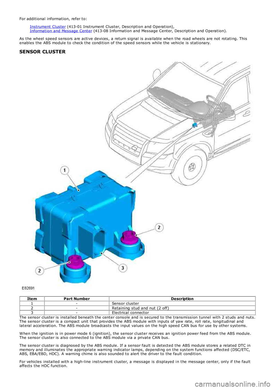
SENSOR CLUSTER
ItemPart NumberDescription
1-Sens or clus ter
2-Retaini ng s tud and nut (2 off)3-Electrical connect or
The s ens or clus ter is ins tal led beneat h t he cent er cons ole and i s s ecured to the t rans mi ss i on tunnel wit h 2 s t uds and nut s .The s ens or clus ter is a compact unit t hat provides t he ABS module wi th inputs of yaw rate, roll rat e, longit udi nal andlat eral accelerat ion. The ABS module broadcas ts the i nput values on the hi gh speed CAN bus for use by other s ys t ems .
W hen t he i gni ti on is i n power mode 6 (ignit ion), the s ens or cl us t er recei ves an ignit ion power feed from t he ABS module.The s ens or clus ter is als o connected t o t he ABS module via a privat e CAN bus .
The s ens or clus ter is diagnos ed by t he ABS module. If a s ensor faul t is det ect ed t he ABS module s t ores a relat ed DTC inmemory and il lumi nat es t he appropriat e warni ng indicator l amps, dependi ng on t he s yst em funct ions affect ed (DSC/ETC,ABS, EBA/EBD, HDC). A warning chime is al s o s ounded t o alert the driver to the fault condi ti on.
For vehicles ins tall ed wit h a high-l ine i ns t rument clus ter, a mes s age is di spl ayed in t he mes sage center, onl y if t he faul taffect s t he HDC funct ion.
Page 515 of 3229
For addit ional informat ion, refer t o:
Ins trument Clus ter (413-01 Ins t rument Clus t er, Descripti on and Operat ion),Informat ion and Mes s age Cent er (413-08 Informati on and Mes sage Cent er, Descripti on and Operat ion).
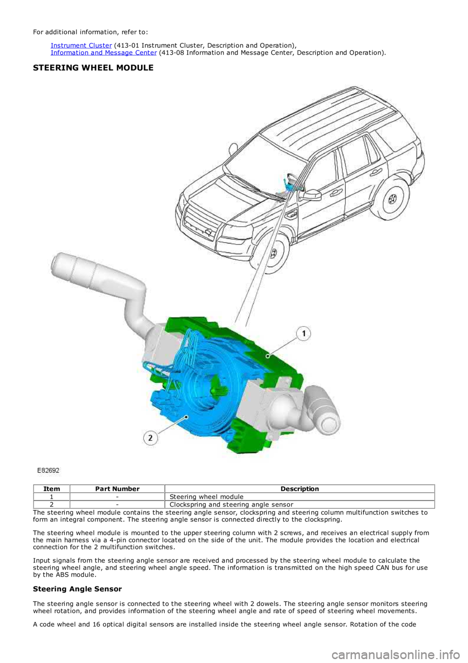
STEERING WHEEL MODULE
ItemPart NumberDescription
1-St eering wheel module2-Cl ocks pring and s t eering angle s ens or
The s teeri ng wheel modul e cont ains t he s teering angle s ens or, clocks pri ng and s teering col umn mul ti functi on s wit ches t oform an int egral component . The s teeri ng angle s ensor i s connected di rectl y to the cl ocks pring.
The s teeri ng wheel modul e is mount ed t o t he upper s t eering column wit h 2 s crews , and receives an elect rical s uppl y fromt he main harnes s vi a a 4-pi n connector l ocat ed on t he si de of the uni t. The module provides t he locati on and elect ricalconnecti on for t he 2 mul ti functi on swit ches .
Input s ignals from t he s teeri ng angl e s ensor are received and process ed by t he s teering wheel modul e t o calculate thes teeri ng wheel angle, and s t eering wheel angl e s peed. The i nformat ion is t rans mit t ed on the hi gh s peed CAN bus for us eby t he ABS module.
Steering Angle Sensor
The s teeri ng angle s ensor i s connected t o t he s teering wheel wit h 2 dowels . The s teering angle s ens or moni tors s teeri ngwheel rotat ion, and provides i nformat ion of t he s teering wheel angl e and rat e of s peed of s t eering wheel movements .
A code wheel and 16 opt ical digit al sens ors are ins t al led i nsi de t he s teeri ng wheel angle sens or. Rotat ion of t he code
Page 613 of 3229
The intermediat e s haft is us ed to locat e the cams haft drive s haft gear wheel in t he cylinder block. The shaft is journaled wit h adouble conical roller bearing. The auxiliary unit s haft drive gear wheel is in 2 pieces , wit h t he narrow half being s pring tensioned inthe opposit e direct ion t o t he wide half. This feat ure reduces nois e becaus e gear play is eliminat ed. Only t he wide half drives theauxiliary unit's gear wheel. The cams haft chain gear wheel is of t he conventional design.
The s haft is sealed against the exhaust side (i.e. the rear s ide of t he cylinder block) by a s ealing was her. To remove or inst all t hewasher, t he flywheel/flexplate must be removed.
Camshaft Drive O uter Shaft
The cams haft drive outer s haft is journaled at the front end of t he s haft with a double row bearing in t he gear hous ing. Needlebearings are us ed at t he rear end (pulley s ide) against t he auxiliary unit s haft . The camshaft drive out er s haft gear wheel is in 2pieces , a wide and a narrow half t o reduce nois e. The cams haft chain gear wheel is als o locat ed on the s haft and is us ed to drivethe cams hafts chain.
Auxiliary Unit Inner Shaft
The auxiliary unit inner s haft is journaled at t he front end of t he shaft (generator s ide) in t he gear housing with a s ingle rowbearing. Needle bearings are used at the rear end (pulley s ide) against the cams haft drive shaft . There is a pulley at t he rear endof the s haft that drives t he Air Condit ioning (AC) compress or and the power s t eering pump, via a polyvee belt . The shaft als odrives t he generat or at t he front end, via a sleeve connect or.
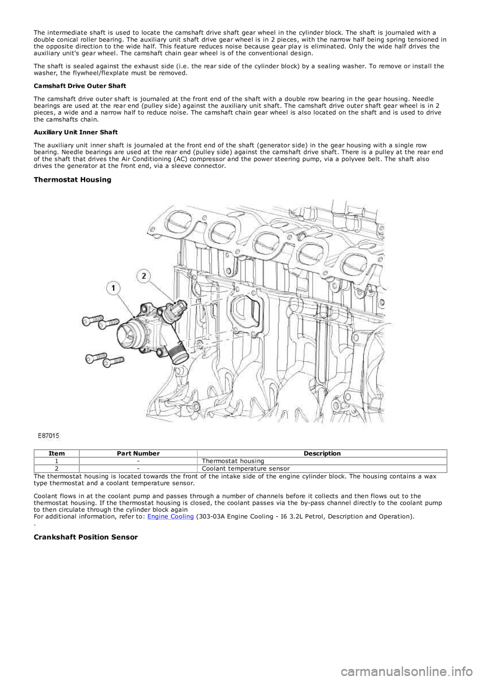
Thermostat Housing
ItemPart NumberDescription1-Thermost at hous ing2-Coolant t emperat ure s ens orThe t hermos tat hous ing is located t owards the front of t he int ake s ide of t he engine cylinder block. The hous ing contains a waxtype t hermost at and a coolant temperat ure sens or.
Coolant flows in at t he coolant pump and pas s es through a number of channels before it collect s and t hen flows out t o t hethermos t at housing. If t he t hermost at hous ing is closed, t he coolant pass es via t he by-pass channel directly to t he coolant pumpto then circulat e t hrough t he cylinder block againFor addit ional information, refer t o: Engine Cooling (303-03A Engine Cooling - I6 3.2L Pet rol, Des cription and Operat ion)..
Crankshaft Position Sensor
Page 614 of 3229
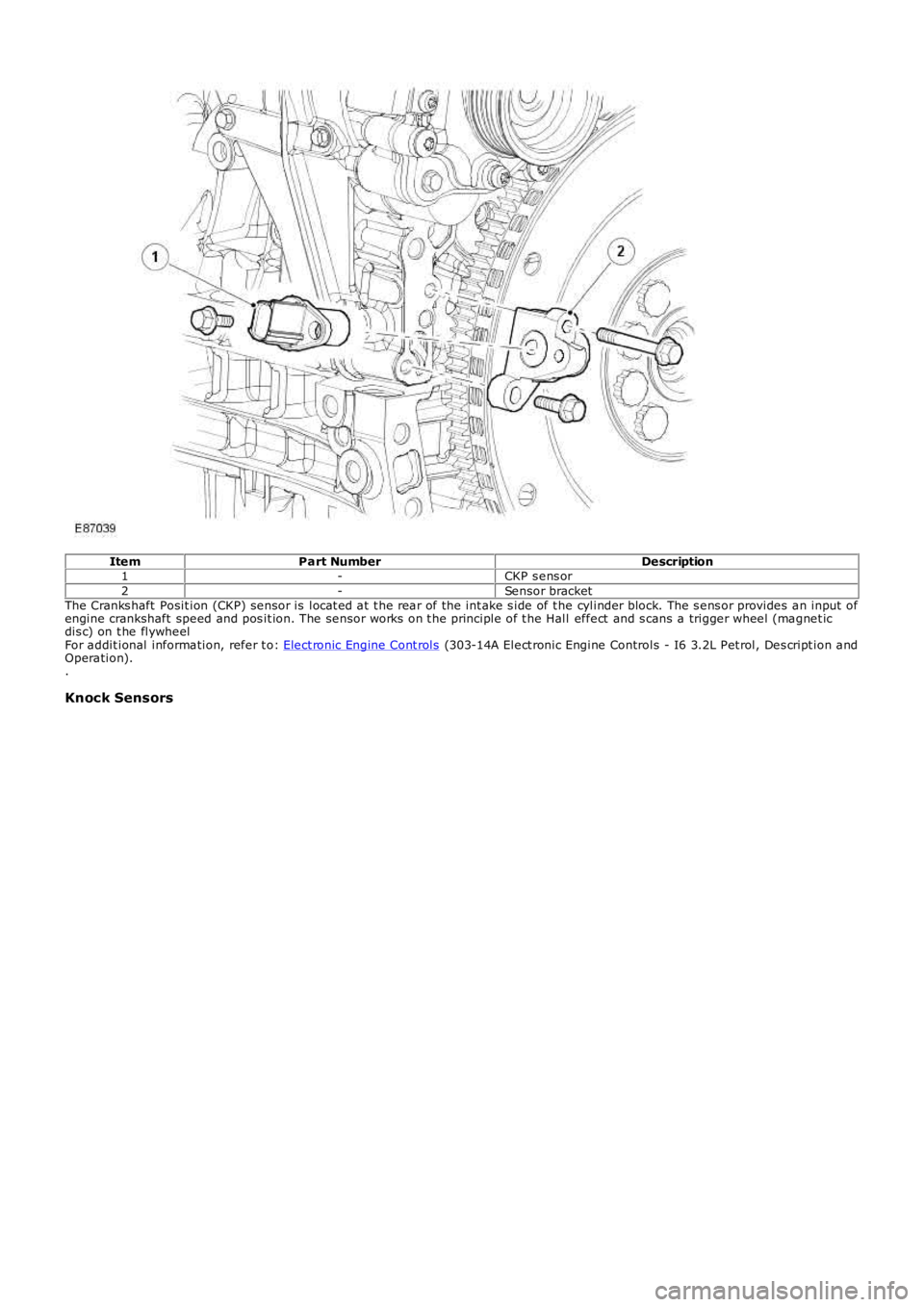
ItemPart NumberDescription1-CKP s ens or2-Sensor bracketThe Cranks haft Posit ion (CKP) sensor is locat ed at t he rear of the int ake s ide of t he cylinder block. The s ens or provides an input ofengine crankshaft speed and pos it ion. The sensor works on t he principle of t he Hall effect and s cans a trigger wheel (magnet icdis c) on t he flywheelFor addit ional information, refer t o: Elect ronic Engine Cont rols (303-14A Elect ronic Engine Controls - I6 3.2L Pet rol, Des cript ion andOperation)..
Knock Sensors
Page 625 of 3229
For addit ional information, refer t o: Elect ronic Engine Cont rols (303-14A Elect ronic Engine Controls - I6 3.2L Pet rol, Des cript ion andOperation).
Variable Camshaft Timing Solenoid and Camshaft Position Sensors
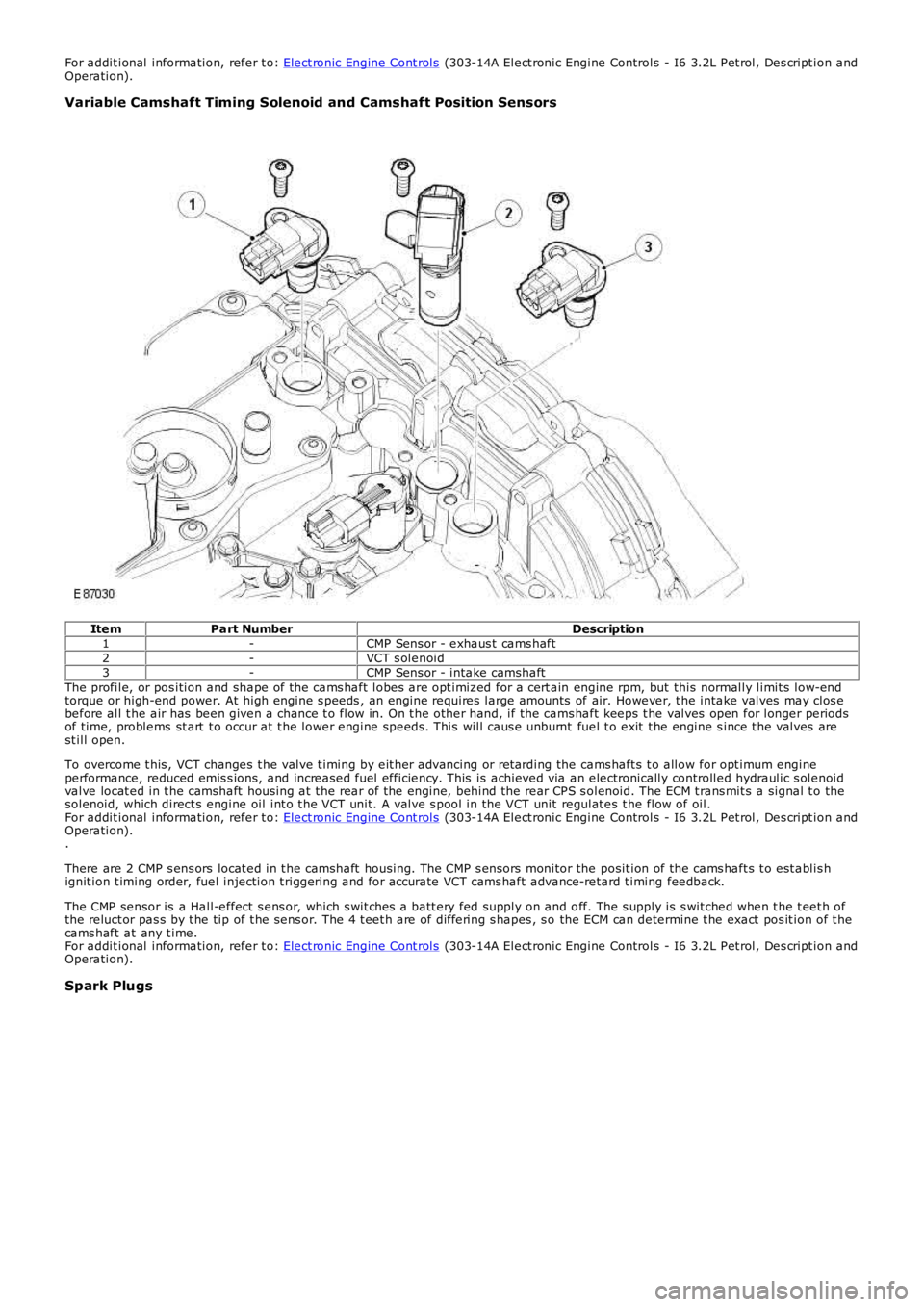
ItemPart NumberDescription1-CMP Sens or - exhaus t cams haft2-VCT s olenoid3-CMP Sens or - intake camshaftThe profile, or pos ition and shape of the cams haft lobes are opt imiz ed for a cert ain engine rpm, but this normally limit s low-endtorque or high-end power. At high engine s peeds , an engine requires large amounts of air. However, t he intake valves may clos ebefore all t he air has been given a chance t o flow in. On t he other hand, if the cams haft keeps t he valves open for longer periodsof time, problems st art t o occur at t he lower engine speeds . This will caus e unburnt fuel t o exit t he engine s ince t he valves arest ill open.
To overcome t his , VCT changes t he valve t iming by eit her advancing or ret arding the cams haft s t o allow for opt imum engineperformance, reduced emis s ions, and increased fuel efficiency. This is achieved via an electronically controlled hydraulic s olenoidvalve locat ed in t he camshaft housing at t he rear of t he engine, behind the rear CPS s olenoid. The ECM t rans mit s a signal t o thesolenoid, which direct s engine oil int o t he VCT unit. A valve s pool in the VCT unit regulat es t he flow of oil.For addit ional information, refer t o: Elect ronic Engine Cont rols (303-14A Elect ronic Engine Controls - I6 3.2L Pet rol, Des cript ion andOperation)..
There are 2 CMP s ens ors locat ed in t he camshaft housing. The CMP s ensors monitor the posit ion of the cams haft s t o est ablis hignit ion t iming order, fuel injection t riggering and for accurate VCT cams haft advance-retard t iming feedback.
The CMP sensor is a Hall-effect s ens or, which s wit ches a batt ery fed supply on and off. The s upply is s wit ched when t he t eet h ofthe reluct or pas s by t he tip of t he sens or. The 4 t eet h are of differing s hapes , s o the ECM can determine t he exact pos it ion of t hecams haft at any t ime.For addit ional information, refer t o: Elect ronic Engine Cont rols (303-14A Elect ronic Engine Controls - I6 3.2L Pet rol, Des cript ion andOperation).
Spark Plugs
Page 628 of 3229
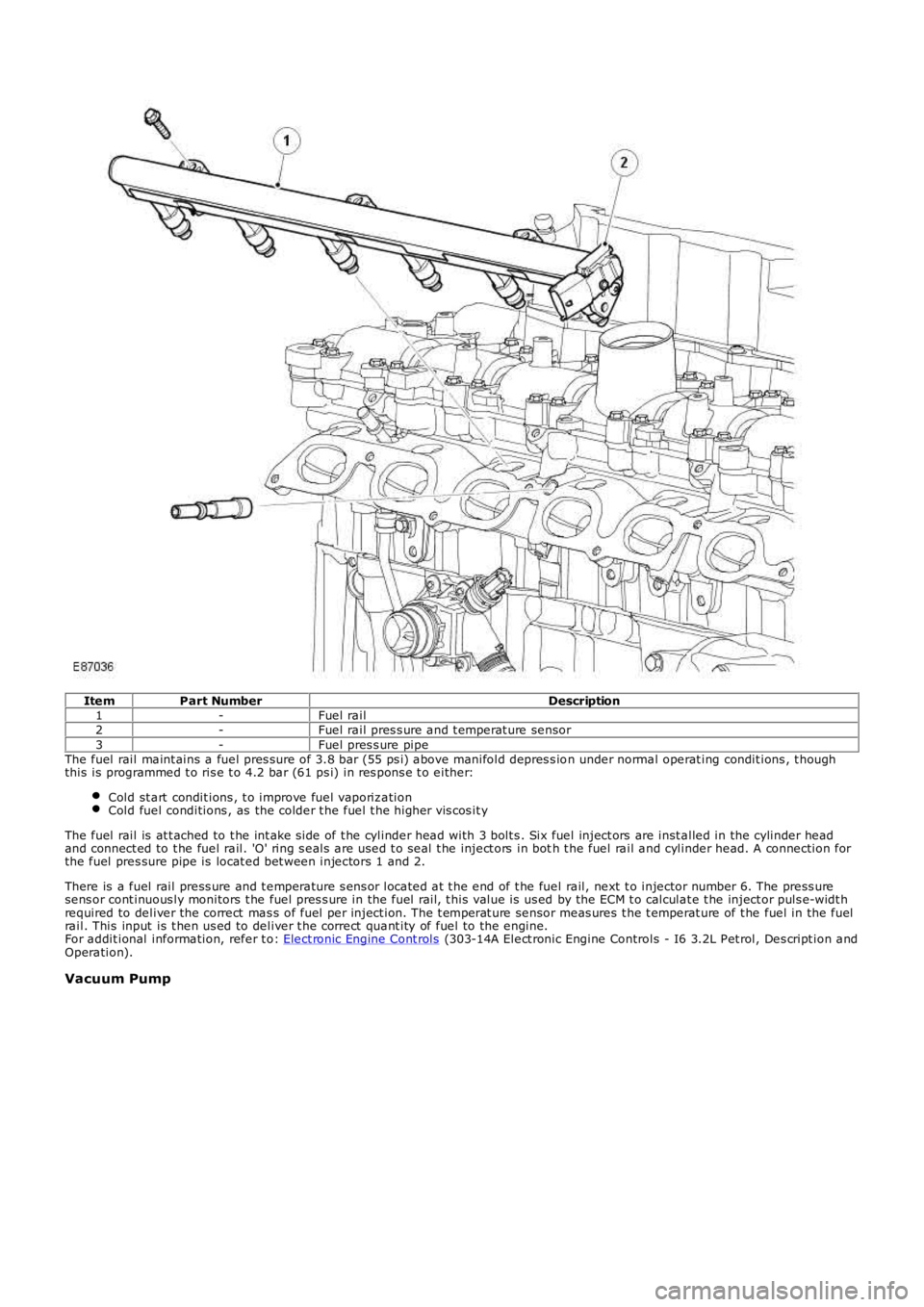
ItemPart NumberDescription1-Fuel rail2-Fuel rail pres s ure and t emperat ure sensor3-Fuel pres s ure pipeThe fuel rail maint ains a fuel pres sure of 3.8 bar (55 ps i) above manifold depres s ion under normal operat ing condit ions , t houghthis is programmed t o ris e t o 4.2 bar (61 ps i) in res pons e t o either:
Cold st art condit ions , t o improve fuel vaporiz ationCold fuel conditions , as the colder t he fuel t he higher vis cos it y
The fuel rail is at t ached to t he int ake s ide of t he cylinder head with 3 bolt s . Six fuel inject ors are inst alled in the cylinder headand connect ed to t he fuel rail. 'O' ring s eals are used t o seal t he inject ors in both t he fuel rail and cylinder head. A connection forthe fuel pres sure pipe is locat ed bet ween injectors 1 and 2.
There is a fuel rail press ure and t emperature s ens or located at t he end of t he fuel rail, next t o injector number 6. The press uresens or cont inuous ly monitors t he fuel pres s ure in the fuel rail, t his value is us ed by the ECM t o calculat e t he inject or puls e-widt hrequired to deliver the correct mas s of fuel per inject ion. The t emperat ure sensor meas ures t he t emperat ure of t he fuel in the fuelrail. This input is t hen us ed to deliver t he correct quant ity of fuel to the engine.For addit ional information, refer t o: Elect ronic Engine Cont rols (303-14A Elect ronic Engine Controls - I6 3.2L Pet rol, Des cript ion andOperation).
Vacuum Pump
Page 638 of 3229
Oil Pan
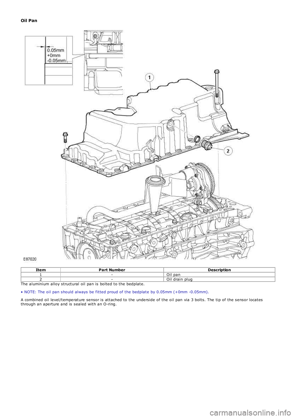
ItemPart NumberDescription1-Oil pan2-Oil drain plugThe aluminium alloy s truct ural oil pan is bolted t o t he bedplat e.
• NOTE: The oil pan s hould always be fit ted proud of t he bedplat e by 0.05mm (+0mm -0.05mm).
A combined oil level/t emperat ure sensor is at t ached to t he underside of t he oil pan via 3 bolt s. The tip of the s ens or locat esthrough an aperture and is s ealed wit h an O-ring.