2006 LAND ROVER FRELANDER 2 sensor
[x] Cancel search: sensorPage 639 of 3229
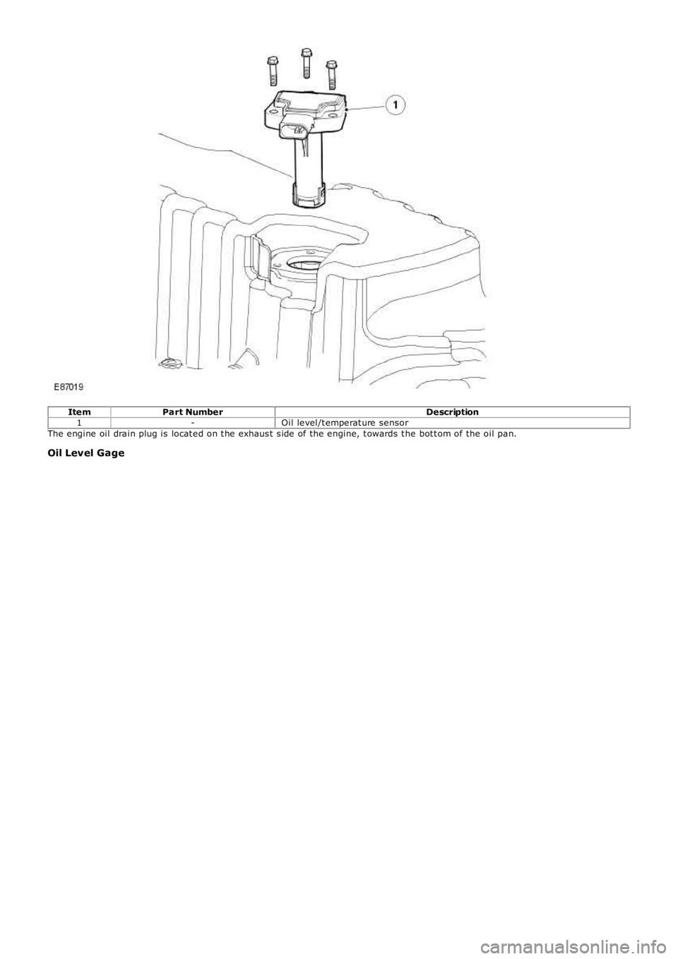
ItemPart NumberDescription1-Oil level/t emperat ure sensorThe engine oil drain plug is locat ed on t he exhaus t s ide of the engine, t owards t he bot t om of the oil pan.
Oil Level Gage
Page 667 of 3229
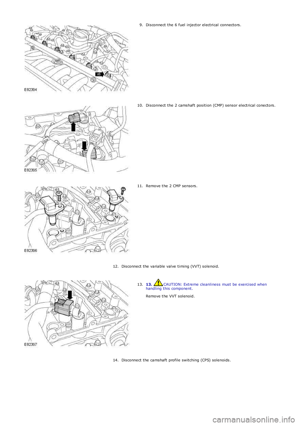
Di sconnect the 6 fuel inject or el ectri cal connectors.
9. Di sconnect the 2 camshaft positi on (CMP) sensor el ectrical conectors.
10. Remove t he 2 CMP sensors.
11.
Disconnect the variable val ve ti ming (VVT) solenoi d.
12. 13. CAUTION: Extreme cleanli ness must be exerci sed when
handling this component.
Remove t he VVT sol enoid.
13.
Disconnect the camshaft profil e switching (CPS) solenoi ds.
14.
Page 671 of 3229
Torque:
6 Nm 13.
CAUTIONS: Extreme cleanli ness must be exerci sed when handli ng this component.
A new O-ring seal is t o be instal led.
Install the CPS solenoids.
Torque: 10 Nm 13.
Connect the CPS solenoi ds.
14.
15. CAUTIONS: Apply clean engi ne oil to t he VVT sol enoid shaft.
Extreme cleanli ness must be exerci sed when handli ng this component.
A new O-ring seal is t o be instal led.
Install the VVT solenoid.
Torque: 10 Nm 15.
Connect the VVT solenoid.
16.
Install the CMP sensors.
Torque: 10 Nm 17.
Connect and secure the CMP sensor electrical connectors.
18.
Connect the fuel i nj ector electrical connectors.
19.
Connect the ground cabl e.
Torque: 6 Nm 20.
Install the engine mount.
Refer to: Engine Mount RH (303-01A Engi ne - I6 3.2L Petrol, Removal and
Installation).
21.
Install the i gniti on coil-on-pl ugs.
Refer to: Igni tion Coil-On-Plug (303-07A Engine Igni tion, Removal and
Installation).
22.
Install the crankcase vent oil separator.
Refer to: Crankcase Vent Oi l Separator (303-08A Engine Emi ssi on Control - I6 3.2L
Petrol, Removal and Installation).
23.
Install the ti ming component housi ng.
Refer to: Timing Components Housing (303-01A Engine - I6 3.2L Pet rol , Removal
and Install ati on).
24.
Connect the battery ground cable and instal l the cover.
Refer to: Specifi cati ons (414-00 Battery and Charging System - General
Information, Specifi cati ons).
25.
Page 763 of 3229
ItemPart NumberDescription
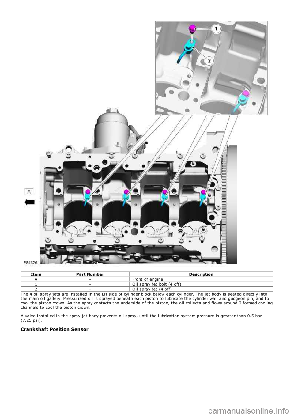
A-Front of engine1-Oil s pray jet bol t (4 off)
2-Oil s pray jet (4 off)
The 4 oi l s pray jet s are i nst all ed in the LH si de of cyl inder bl ock bel ow each cyl inder. The jet body i s s eat ed direct ly i ntot he main oi l gal lery. Pres s uri zed oi l is s prayed beneat h each pis t on to lubri cat e t he cyl inder wall and gudgeon pin, and t ocool t he pis t on crown. As the spray cont act s t he undersi de of the pi st on, the oi l col lect s and flows around 2 formed cool ingchannels t o cool the pi st on crown.
A valve i nst all ed in the s pray jet body prevent s oil s pray, unti l the l ubricati on s ys t em press ure is great er than 0.5 bar(7.25 ps i).
Crankshaft Position Sensor
Page 775 of 3229
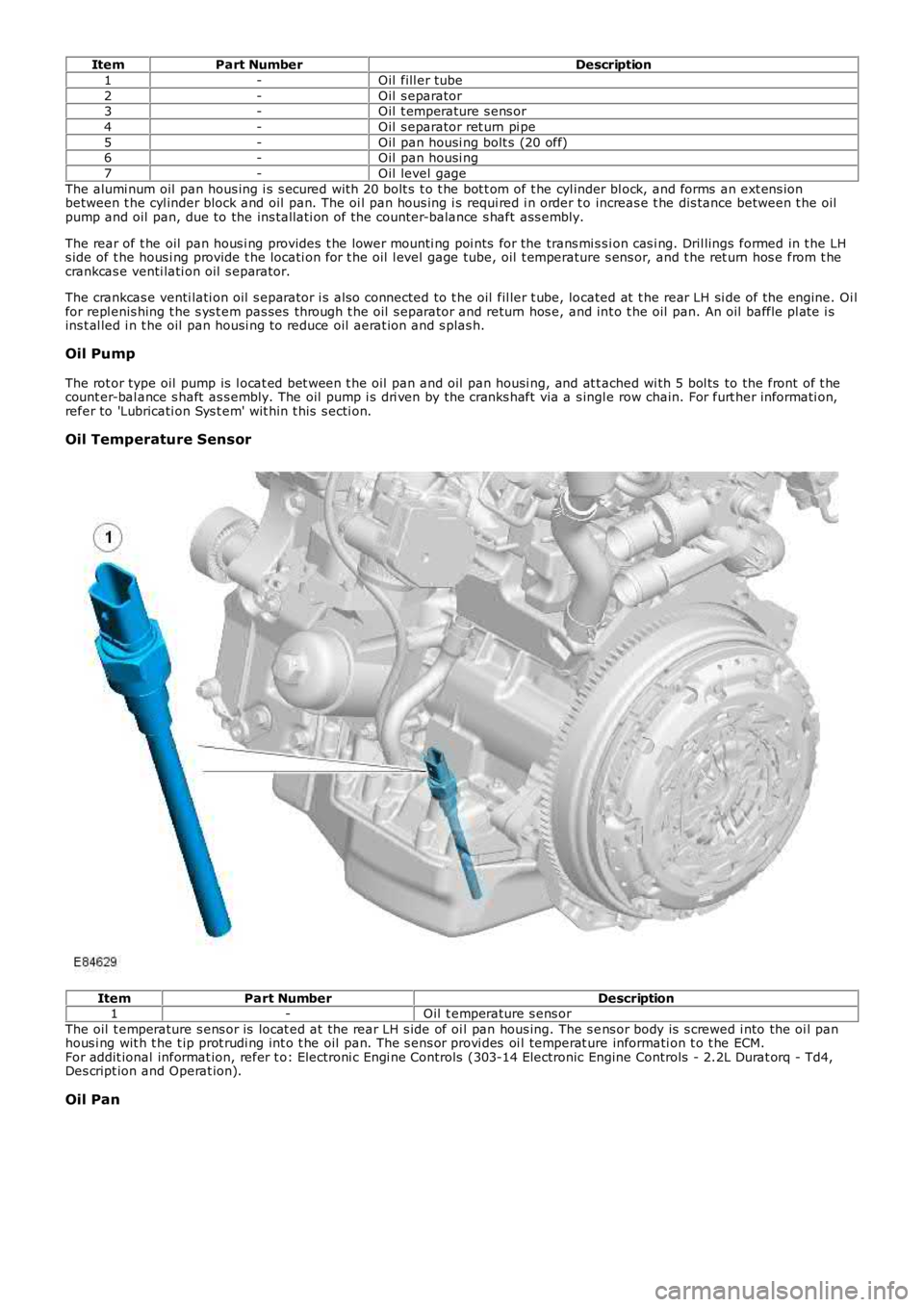
ItemPart NumberDescription
1-Oil fill er tube
2-Oil s eparator3-Oil t emperature s ens or
4-Oil s eparator ret urn pi pe
5-Oil pan housi ng bolt s (20 off)6-Oil pan housi ng
7-Oil level gage
The alumi num oil pan hous ing i s s ecured wit h 20 bolt s t o t he bot t om of t he cyl inder bl ock, and forms an ext ens ionbetween t he cyl inder block and oil pan. The oi l pan hous ing i s requi red i n order t o increas e t he dis tance between t he oilpump and oil pan, due to the ins tall ati on of the counter-balance s haft ass embly.
The rear of t he oil pan hous i ng provides t he lower mounti ng poi nts for the trans mi s si on cas i ng. Dril lings formed in t he LHs ide of t he hous i ng provide t he locati on for t he oil l evel gage tube, oil t emperature s ens or, and t he ret urn hos e from t hecrankcas e venti lati on oil s eparator.
The crankcas e venti lati on oil s eparator i s als o connected to t he oil fil ler t ube, located at t he rear LH si de of the engine. Oi lfor repl enis hing t he s ys t em pas ses through t he oil s eparator and return hos e, and int o t he oil pan. An oil baffle pl ate i sins t al led i n t he oil pan housi ng to reduce oil aerat ion and s plas h.
Oil Pump
The rot or type oil pump is l ocat ed bet ween t he oil pan and oil pan housi ng, and at t ached wi th 5 bol ts to the front of t hecount er-bal ance s haft as s embly. The oil pump i s dri ven by the cranks haft via a s ingle row chain. For furt her informati on,refer to 'Lubricati on Sys t em' wit hin t his s ecti on.
Oil Temperature Sensor
ItemPart NumberDescription1-Oil t emperature s ens or
The oil t emperature s ens or is locat ed at t he rear LH s ide of oi l pan hous ing. The s ens or body is s crewed i nto the oi l panhous i ng wit h t he t ip prot rudi ng int o t he oil pan. The s ens or provi des oi l temperat ure informati on t o t he ECM.For addit ional informat ion, refer t o: Electroni c Engi ne Controls (303-14 Electronic Engine Controls - 2.2L Durat orq - Td4,Des cript ion and Operat ion).
Oil Pan
Page 785 of 3229
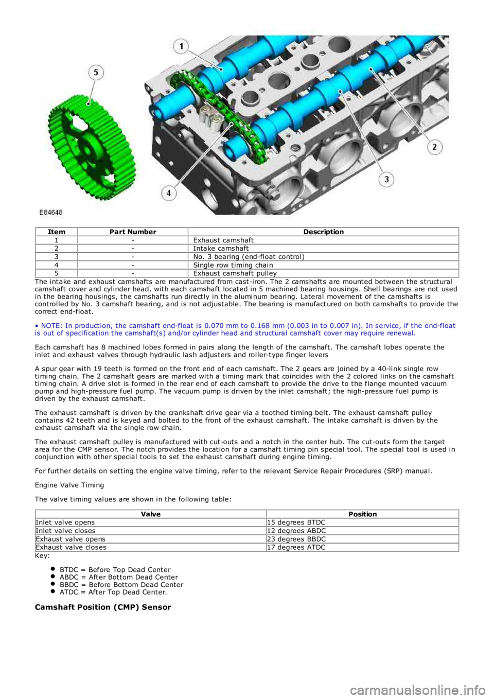
ItemPart NumberDescription
1-Exhaus t cams haft2-Intake cams haft
3-No. 3 bearing (end-fl oat control)
4-Si ngl e row t imi ng chai n5-Exhaus t cams haft pull ey
The int ake and exhaus t cams haft s are manufactured from cast -iron. The 2 cams haft s are mount ed between the s t ructuralcamshaft cover and cyl inder head, wit h each camshaft locat ed i n 5 machined beari ng hous i ngs . Shel l bearings are not us edin the beari ng housi ngs , t he camshafts run direct ly in t he alumi num beari ng. Lateral movement of t he camshaft s i scont rol led by No. 3 cams haft beari ng, and i s not adjust able. The bearing is manufactured on both camshaft s t o provi de thecorrect end-float.
• NOTE: In product ion, t he camshaft end-fl oat i s 0.070 mm t o 0.168 mm (0.003 in t o 0.007 in). In s ervi ce, if t he end-floatis out of s peci fi cat ion t he cams haft(s ) and/or cyli nder head and s t ructural cams haft cover may requi re renewal.
Each cams haft has 8 machi ned lobes formed in pai rs al ong the length of t he cams haft. The cams haft lobes operat e t heinl et and exhaust valves t hrough hydraulic las h adjus ters and rol ler-t ype finger levers
A s pur gear wi th 19 teet h is formed on t he front end of each cams haft. The 2 gears are joined by a 40-li nk s ingle rowt imi ng chai n. The 2 cams haft gears are marked wit h a ti ming mark t hat coi ncides wi th the 2 col ored l inks on t he camshaftt imi ng chai n. A dri ve sl ot is formed in t he rear end of each camshaft to provi de t he drive to t he flange mounted vacuumpump and high-pres sure fuel pump. The vacuum pump is driven by t he inl et cams haft ; the hi gh-pres s ure fuel pump isdri ven by the exhaust cams haft .
The exhaus t camshaft is driven by t he cranks haft drive gear vi a a toothed t iming belt . The exhaus t camshaft pul leycont ains 42 t eeth and is keyed and bol ted to t he front of the exhaust cams haft . The int ake cams haft i s dri ven by theexhaus t camshaft vi a t he s ingle row chain.
The exhaus t camshaft pul ley i s manufactured wit h cut-out s and a not ch in the center hub. The cut -out s form t he t argetarea for the CMP s ens or. The not ch provides the locat ion for a cams haft t imi ng pin speci al tool. The s peci al tool is us ed i nconjunct ion wi th other s pecial t ool s t o s et the exhaus t cams haft duri ng engi ne ti ming.
For furt her det ail s on s ett ing t he engine valve t imi ng, refer t o t he rel evant Service Repair Procedures (SRP) manual.
Engi ne Valve Ti ming
The valve t imi ng val ues are s hown i n t he fol lowing t able:
ValvePositionInlet val ve opens15 degrees BTDC
Inlet val ve clos es12 degrees ABDC
Exhaus t valve opens23 degrees BBDCExhaus t valve clos es17 degrees ATDC
Key:
BTDC = Before Top Dead Cent erABDC = Aft er Bot t om Dead CenterBBDC = Before Bot t om Dead CenterATDC = Aft er Top Dead Cent er.
Camshaft Position (CMP) Sensor
Page 805 of 3229
1
2
3
4
5
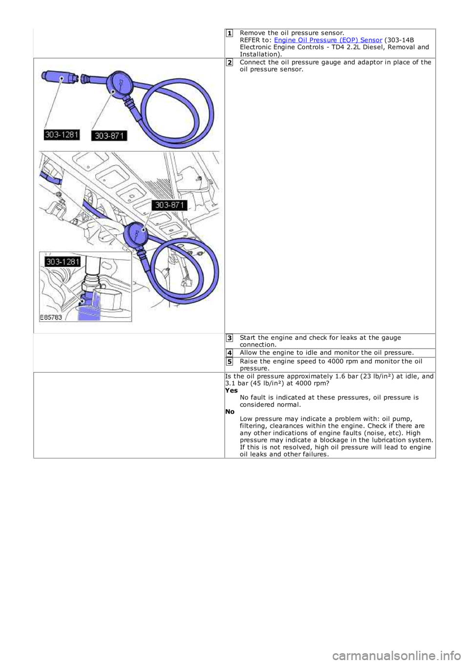
Remove the oi l press ure s ens or.REFER t o: Engi ne Oi l Press ure (EOP) Sensor (303-14BElect roni c Engi ne Cont rol s - TD4 2.2L Dies el, Removal andIns tal lat ion).
Connect the oi l pres sure gauge and adapt or i n place of t heoil pres s ure s ensor.
Start the engine and check for leaks at t he gaugeconnect ion.
Allow the engi ne to idle and monit or t he oil pres s ure.
Rai s e t he engi ne s peed t o 4000 rpm and moni tor t he oilpres sure.
Is t he oil pres s ure approxi matel y 1.6 bar (23 lb/in²) at idle, and3.1 bar (45 lb/i n²) at 4000 rpm?YesNo faul t is i ndi cat ed at t hes e press ures , oil pres s ure i scons idered normal.NoLow pres s ure may indicate a problem wit h: oil pump,fi lt ering, clearances wit hin t he engine. Check i f there areany ot her indicati ons of engine fault s (noi se, et c). Highpres sure may i ndi cat e a bl ockage i n the lubri cat ion s ys tem.If t his i s not res olved, hi gh oil pres s ure will l ead to engi neoil leaks and other fai lures .
Page 914 of 3229
1
2
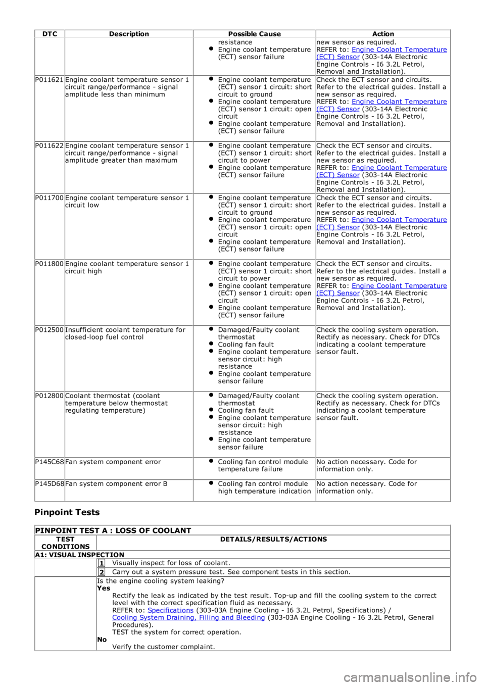
DT CDescriptionPossible CauseAction
res is t anceEngi ne cool ant t emperat ure(ECT) s ens or fai lure
new s ens or as requi red.REFER to: Engine Coolant Temperature(ECT) Sensor (303-14A Electroni cEngi ne Cont rol s - I6 3.2L Pet rol,Removal and Inst all at ion).
P011621Engine coolant temperature s ens or 1circui t range/performance - s ignalampl it ude les s than minimum
Engi ne cool ant t emperat ure(ECT) s ens or 1 circui t: shortci rcuit t o groundEngi ne cool ant t emperat ure(ECT) s ens or 1 circui t: openci rcuitEngi ne cool ant t emperat ure(ECT) s ens or fai lure
Check t he ECT s ensor and circui ts .Refer to the el ect ri cal guides . Ins tal l anew s ens or as requi red.REFER to: Engine Coolant Temperature(ECT) Sensor (303-14A Electroni cEngi ne Cont rol s - I6 3.2L Pet rol,Removal and Inst all at ion).
P011622Engine coolant temperature s ens or 1circui t range/performance - s ignalampl it ude greater t han maxi mum
Engi ne cool ant t emperat ure(ECT) s ens or 1 circui t: shortci rcuit t o powerEngi ne cool ant t emperat ure(ECT) s ens or fai lure
Check t he ECT s ensor and circui ts .Refer to the el ect ri cal guides . Ins tal l anew s ens or as requi red.REFER to: Engine Coolant Temperature(ECT) Sensor (303-14A Electroni cEngi ne Cont rol s - I6 3.2L Pet rol,Removal and Inst all at ion).
P011700Engine coolant temperature s ens or 1circui t lowEngi ne cool ant t emperat ure(ECT) s ens or 1 circui t: shortci rcuit t o groundEngi ne cool ant t emperat ure(ECT) s ens or 1 circui t: openci rcuitEngi ne cool ant t emperat ure(ECT) s ens or fai lure
Check t he ECT s ensor and circui ts .Refer to the el ect ri cal guides . Ins tal l anew s ens or as requi red.REFER to: Engine Coolant Temperature(ECT) Sensor (303-14A Electroni cEngi ne Cont rol s - I6 3.2L Pet rol,Removal and Inst all at ion).
P011800Engine coolant temperature s ens or 1circui t highEngi ne cool ant t emperat ure(ECT) s ens or 1 circui t: shortci rcuit t o powerEngi ne cool ant t emperat ure(ECT) s ens or 1 circui t: openci rcuitEngi ne cool ant t emperat ure(ECT) s ens or fai lure
Check t he ECT s ensor and circui ts .Refer to the el ect ri cal guides . Ins tal l anew s ens or as requi red.REFER to: Engine Coolant Temperature(ECT) Sensor (303-14A Electroni cEngi ne Cont rol s - I6 3.2L Pet rol,Removal and Inst all at ion).
P012500Insuffi ci ent coolant t emperature forclos ed-l oop fuel cont rolDamaged/Faul ty coolantthermost atCool ing fan faul tEngi ne cool ant t emperat ures ens or ci rcuit : highres is t anceEngi ne cool ant t emperat ures ens or fai lure
Check t he cool ing s ys tem operati on.Rect ify as neces s ary. Check for DTCsindicati ng a coolant temperat ures ens or fault .
P012800Coolant t hermos tat (coolantt emperat ure below thermost atregul ati ng temperat ure)
Damaged/Faul ty coolantthermost atCool ing fan faul tEngi ne cool ant t emperat ures ens or ci rcuit : highres is t anceEngi ne cool ant t emperat ures ens or fai lure
Check t he cool ing s ys tem operati on.Rect ify as neces s ary. Check for DTCsindicati ng a coolant temperat ures ens or fault .
P145C68Fan s yst em component errorCool ing fan cont rol moduletemperat ure fail ureNo acti on neces sary. Code forinformat ion only.
P145D68Fan s yst em component error BCool ing fan cont rol modulehigh t emperature i ndi cat ionNo acti on neces sary. Code forinformat ion only.
Pinpoint Tests
PINPOINT TEST A : LOSS OF COOLANT
T ESTCO NDIT IONSDET AILS/RESULT S/ACT IONS
A1: VISUAL INSPECT IONVis ually ins pect for l oss of coolant .
Carry out a s ys t em press ure tes t. See component t es ts i n t his s ecti on.
Is the engine cooli ng sys t em l eaking?YesRect ify t he leak as i ndi cat ed by t he tes t res ult . Top-up and fil l t he cooling sys tem t o the correctlevel wit h t he correct s pecificati on fl uid as necess ary.REFER to: Speci fi cat ions (303-03A Engi ne Cool ing - I6 3.2L Petrol , Specificati ons) /Cool ing Sys tem Drai ning, Fi ll ing and Bl eeding (303-03A Engine Cooli ng - I6 3.2L Pet rol, GeneralProcedures).TEST the s ys tem for correct operat ion.NoVeri fy t he cust omer compl aint.