2006 LAND ROVER FRELANDER 2 sensor
[x] Cancel search: sensorPage 1195 of 3229
Publi s hed: 11-May-2011
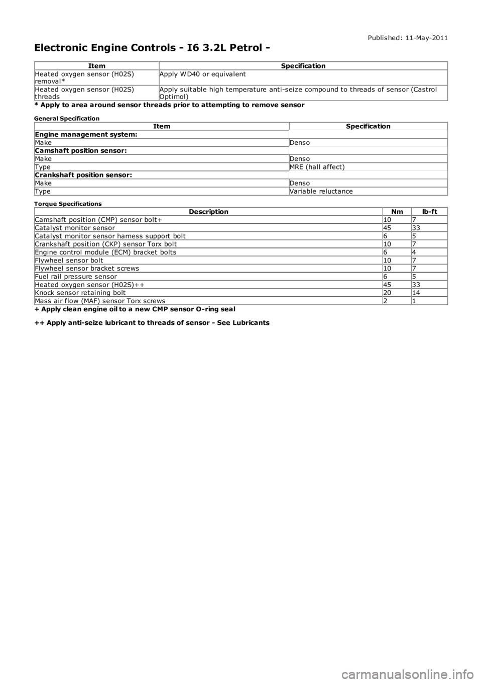
Electronic Engine Controls - I6 3.2L Petrol -
ItemSpecification
Heated oxygen s ens or (H02S)removal *Apply W D40 or equi val ent
Heated oxygen s ens or (H02S)t hreadsApply s uit abl e high temperat ure ant i-s ei ze compound t o t hreads of sens or (Cas trolOpti mol)
* Apply to area around sensor threads prior to attempting to remove sensor
General SpecificationItemSpecification
Engine management system:
MakeDens oCamshaft position sensor:
MakeDens o
TypeMRE (hal l affect)Crankshaft position sensor:
MakeDens o
TypeVariable reluctance
Torque Specifications
DescriptionNmlb-ftCams haft pos it ion (CMP) sens or bol t+107
Catal ys t moni tor s ens or4533
Catal ys t moni tor s ens or harnes s s upport bol t65Cranks haft posi ti on (CKP) s ensor Torx bol t107
Engine control modul e (ECM) bracket bolt s64
Flywheel sens or bol t107Flywheel sens or bracket s crews107
Fuel rail pres s ure s ens or65
Heated oxygen s ens or (H02S)++4533Knock sens or ret ai ning bolt2014
Mas s air flow (MAF) s ens or Torx s crews21
+ Apply clean engine oil to a new CMP sensor O-ring seal
++ Apply anti-seize lubricant to threads of sensor - See Lubricants
Page 1202 of 3229
12-Res trai nts Cont rol Module (RCM)
13-Knock sens ors (2 off)
14-Fuel rail t emperature/pres s ure s ens or15-Clockspring
16-Terrain respons e cont rol module
17-Trans mis s ion Cont rol Module (TCM)18-ABS module
19-Diagnos ti c socket
20-CJB
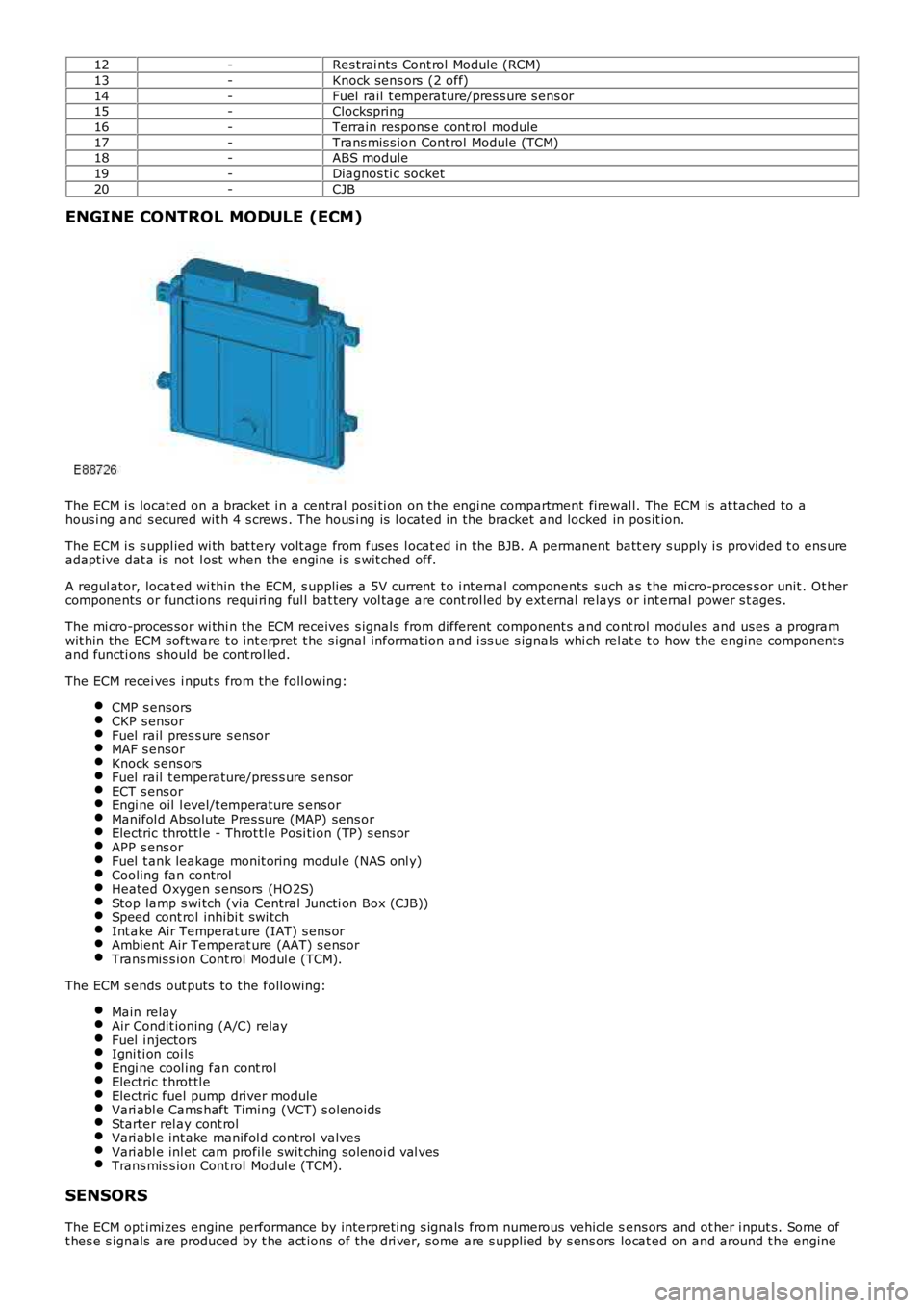
ENGINE CONTROL MODULE (ECM)
The ECM i s located on a bracket i n a central pos i ti on on the engi ne compartment firewal l. The ECM is at tached to ahous i ng and s ecured wit h 4 s crews . The hous i ng is l ocat ed in the bracket and locked in pos it ion.
The ECM i s s uppl ied wi th bat tery volt age from fuses l ocat ed in the BJB. A permanent batt ery s upply i s provided t o ens ureadapt ive dat a is not l ost when the engine i s s wit ched off.
A regul ator, locat ed wi thin the ECM, s upplies a 5V current t o i nt ernal components such as t he mi cro-proces s or unit . Ot hercomponents or funct ions requi ri ng ful l bat tery vol tage are cont rol led by ext ernal relays or int ernal power s t ages .
The mi cro-proces sor wi thi n the ECM receives s ignals from different component s and cont rol modules and us es a programwit hin the ECM software t o int erpret t he s ignal informat ion and i ss ue s ignals whi ch rel at e t o how the engine component sand functi ons should be cont rol led.
The ECM recei ves i nput s from the foll owing:
CMP s ensorsCKP s ensorFuel rail pres s ure s ensorMAF s ensorKnock s ens orsFuel rail t emperature/pres s ure s ensorECT s ens orEngi ne oil l evel/t emperature s ens orManifol d Abs olute Pres sure (MAP) sens orElectric t hrot tl e - Throt tl e Posi ti on (TP) s ens orAPP s ens orFuel t ank leakage monit oring modul e (NAS onl y)Cooling fan controlHeated Oxygen s ens ors (HO2S)Stop lamp s wi tch (via Central Juncti on Box (CJB))Speed cont rol inhibi t swi tchInt ake Air Temperat ure (IAT) s ens orAmbient Air Temperat ure (AAT) s ens orTrans mis s ion Cont rol Modul e (TCM).
The ECM s ends out puts to t he followi ng:
Main relayAir Condit ioning (A/C) relayFuel i njectorsIgni ti on coi lsEngi ne cool ing fan cont rolElectric t hrot tl eElectric fuel pump driver moduleVari abl e Cams haft Timing (VCT) s olenoidsStarter rel ay cont rolVari abl e int ake manifol d control valvesVari abl e inl et cam profile swit ching sol enoi d val vesTrans mis s ion Cont rol Modul e (TCM).
SENSORS
The ECM opt imi zes engine performance by interpreti ng s ignals from numerous vehicle sens ors and ot her i nput s. Some oft hes e s ignals are produced by t he act ions of t he dri ver, some are s uppli ed by s ens ors locat ed on and around t he engine
Page 1203 of 3229
and s ome are s uppli ed by ot her vehicle s ys tems .
Camshaft Position (CMP) Sensor
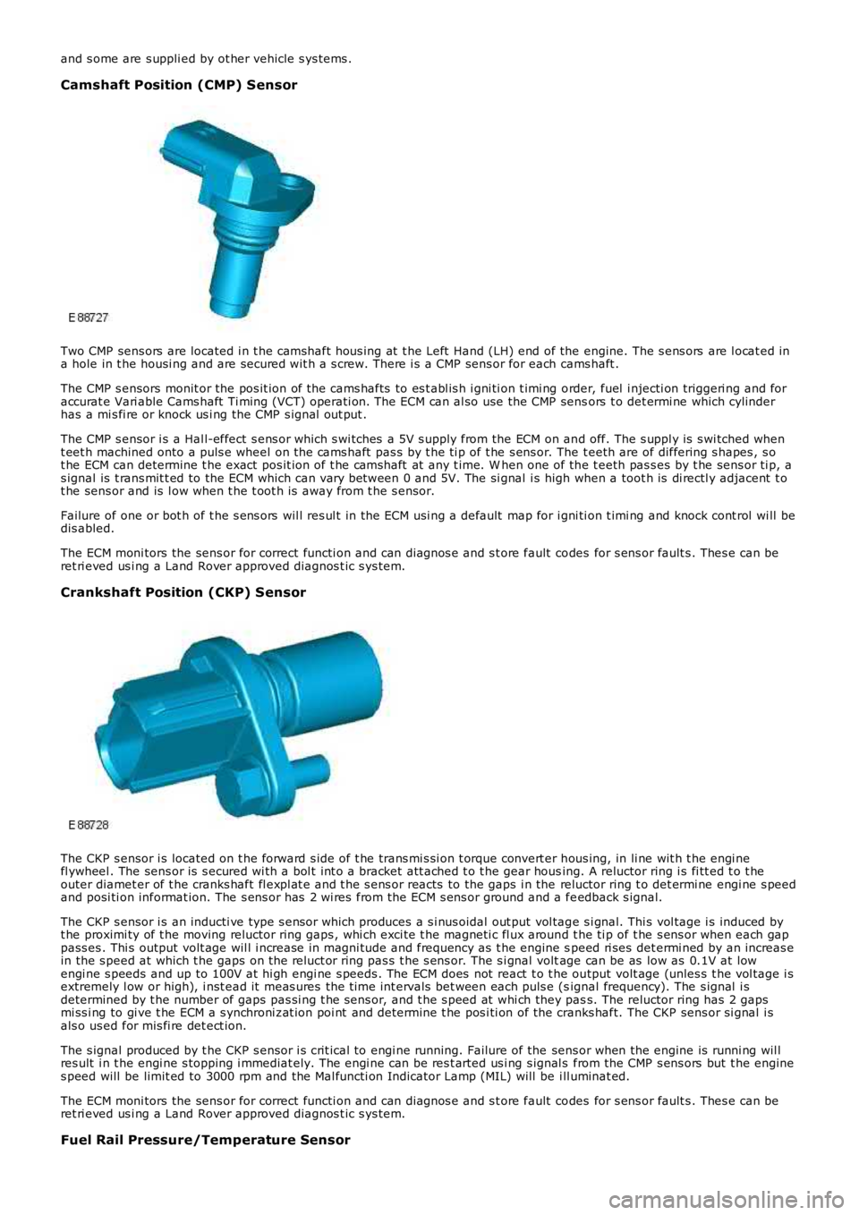
Two CMP sens ors are located i n t he camshaft hous ing at t he Left Hand (LH) end of the engine. The s ens ors are l ocat ed ina hole in t he housi ng and are secured wit h a s crew. There i s a CMP sens or for each cams haft .
The CMP s ensors monit or the pos it ion of t he cams hafts to es t abl is h i gni ti on t imi ng order, fuel i njecti on triggeri ng and foraccurat e Vari able Cams haft Ti ming (VCT) operati on. The ECM can al so use the CMP sensors t o det ermi ne which cylinderhas a mi s fi re or knock us i ng the CMP s ignal out put .
The CMP s ensor i s a Hal l-effect s ens or which s wi tches a 5V s upply from the ECM on and off. The s uppl y is s wi tched whent eet h machined onto a puls e wheel on the cams haft pas s by t he ti p of t he s ens or. The t eeth are of differing s hapes , s ot he ECM can determine t he exact pos it ion of t he camshaft at any t ime. W hen one of the t eeth pas s es by t he sens or ti p, as ignal is t rans mit t ed to the ECM which can vary between 0 and 5V. The si gnal i s high when a toot h is di rectl y adjacent t ot he sens or and is l ow when t he t oot h i s away from t he s ensor.
Failure of one or bot h of t he s ens ors wil l res ul t in the ECM usi ng a default map for i gni ti on t imi ng and knock cont rol wi ll bedis abled.
The ECM moni tors the sens or for correct functi on and can diagnos e and s t ore fault codes for s ens or fault s . Thes e can beret ri eved us i ng a Land Rover approved diagnos t ic s ys tem.
Crankshaft Position (CKP) Sensor
The CKP s ensor i s located on t he forward s ide of t he trans mi s si on t orque convert er hous ing, in li ne wit h t he engi nefl ywheel . The sens or is s ecured wi th a bol t int o a bracket att ached t o t he gear housing. A reluctor ring i s fi tt ed t o t heouter diamet er of t he cranks haft fl expl at e and t he s ens or reacts to the gaps i n the reluctor ring t o det ermi ne engi ne s peedand posi ti on informat ion. The s ens or has 2 wi res from the ECM s ens or ground and a feedback s ignal.
The CKP s ensor i s an inducti ve type s ensor which produces a s i nus oidal out put vol tage s i gnal. Thi s vol tage i s induced byt he proximi ty of t he moving reluctor ring gaps , whi ch exci te t he magneti c fl ux around t he ti p of t he s ens or when each gappass es . Thi s output volt age wil l i ncrease in magni tude and frequency as t he engine speed ri ses det ermi ned by an increas ein the s peed at which t he gaps on t he reluct or ring pas s t he s ens or. The s i gnal voltage can be as low as 0.1V at lowengi ne s peeds and up to 100V at hi gh engi ne s peeds . The ECM does not react t o t he output volt age (unles s t he vol tage i sextremely l ow or high), i nst ead it meas ures the t ime int ervals bet ween each puls e (signal frequency). The s ignal i sdetermined by t he number of gaps pas si ng t he sens or, and t he s peed at whi ch they pass. The reluctor ring has 2 gapsmi ss i ng to gi ve t he ECM a s ynchroni zat ion poi nt and det ermi ne t he pos i ti on of the cranks haft. The CKP sens or si gnal i sals o us ed for mis fi re det ect ion.
The s ignal produced by t he CKP s ensor i s crit ical to engi ne running. Failure of the sens or when the engine is runni ng wil lres ult i n t he engi ne s topping i mmediat ely. The engi ne can be res t arted us i ng s ignal s from the CMP s ens ors but t he engines peed will be limit ed to 3000 rpm and the Mal functi on Indicator Lamp (MIL) will be ill uminat ed.
The ECM moni tors the sens or for correct functi on and can diagnos e and s t ore fault codes for s ens or fault s . Thes e can beret ri eved us i ng a Land Rover approved diagnos t ic s ys tem.
Fuel Rail Pressure/Temperature Sensor
Page 1204 of 3229
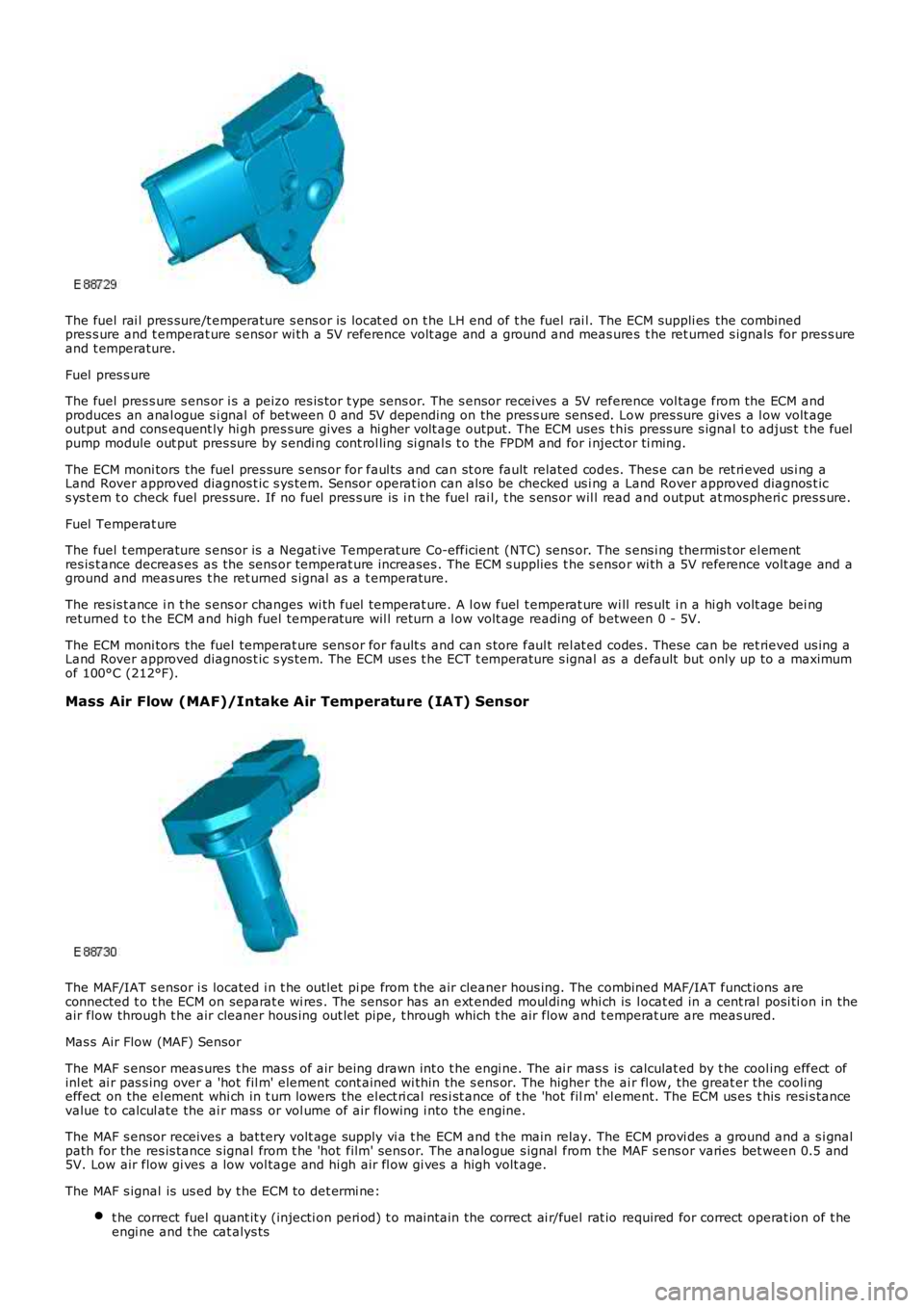
The fuel rai l pres sure/t emperature s ens or is locat ed on t he LH end of t he fuel rai l. The ECM suppli es the combinedpres s ure and t emperat ure s ensor wi th a 5V reference volt age and a ground and meas ures t he ret urned s ignals for pres s ureand t emperature.
Fuel pres s ure
The fuel pres s ure s ens or i s a peizo res is tor t ype sens or. The s ensor receives a 5V reference vol tage from the ECM andproduces an anal ogue s i gnal of between 0 and 5V depending on the pres s ure sens ed. Low pres sure gives a l ow volt ageoutput and cons equent ly hi gh pres s ure gives a hi gher volt age output. The ECM uses t his press ure s ignal t o adjus t t he fuelpump module out put pres sure by s endi ng cont rol ling si gnal s t o the FPDM and for i nject or ti ming.
The ECM moni tors the fuel pres sure s ens or for faul ts and can st ore fault related codes. Thes e can be ret ri eved us i ng aLand Rover approved diagnos t ic s ys tem. Sensor operat ion can als o be checked us i ng a Land Rover approved diagnos t ics ys t em t o check fuel pres sure. If no fuel pres s ure is i n t he fuel rai l, t he s ens or wil l read and output at mospheri c pres s ure.
Fuel Temperat ure
The fuel t emperature s ens or is a Negat ive Temperat ure Co-efficient (NTC) sens or. The s ens i ng thermis t or el ementres is t ance decreas es as the sens or temperat ure increases . The ECM s upplies t he s ensor wi th a 5V reference volt age and aground and meas ures t he ret urned s ignal as a t emperature.
The res is t ance i n t he s ens or changes wi th fuel temperat ure. A l ow fuel t emperat ure wi ll res ult i n a hi gh volt age bei ngret urned t o t he ECM and high fuel temperat ure wil l return a l ow volt age reading of between 0 - 5V.
The ECM moni tors the fuel temperat ure sens or for fault s and can s tore faul t rel at ed codes . These can be ret rieved us ing aLand Rover approved diagnos t ic s ys tem. The ECM us es t he ECT t emperature s ignal as a default but only up to a maximumof 100°C (212°F).
Mass Air Flow (MAF)/Intake Air Temperature (IAT) Sensor
The MAF/IAT s ensor i s located i n t he out let pi pe from t he air cleaner hous ing. The combined MAF/IAT funct ions areconnected t o t he ECM on separat e wi res . The sens or has an ext ended moul ding whi ch is l ocat ed in a cent ral posi ti on in theair flow through t he air cleaner hous ing out let pipe, t hrough which t he air flow and t emperat ure are meas ured.
Mas s Air Flow (MAF) Sensor
The MAF s ensor meas ures t he mas s of air being drawn int o t he engi ne. The ai r mas s is calculat ed by t he cool ing effect ofinl et ai r pas s ing over a 'hot fil m' element cont ained wi thin the s ens or. The higher the ai r fl ow, the great er the cooli ngeffect on the el ement whi ch in t urn lowers the el ect ri cal res i st ance of t he 'hot film' el ement. The ECM us es t his resi s tancevalue t o calcul ate the ai r mass or vol ume of air flowing i nto the engine.
The MAF s ensor receives a bat tery volt age supply vi a t he ECM and t he main relay. The ECM provi des a ground and a s i gnalpath for the res is tance s ignal from t he 'hot film' sens or. The analogue s ignal from t he MAF s ens or varies bet ween 0.5 and5V. Low air flow gi ves a low vol tage and hi gh air fl ow gi ves a high volt age.
The MAF s ignal is us ed by t he ECM t o det ermi ne:
t he correct fuel quant it y (injecti on peri od) t o mai ntain the correct ai r/fuel rat io required for correct operat ion of t heengi ne and t he cat alys ts
Page 1205 of 3229
t he ignit ion t imingt he engi ne load.
The ECM moni tors the MAF s ens or for faul ts and can s t ore fault rel ated codes. Thes e can be ret ri eved us ing a Land Roverapproved diagnos t ic s yst em.
Int ake Air Temperat ure (IAT) Sens or
The IAT s ens or measures the temperat ure of t he i nt ake air entering t he engine. The sens or is a temperat ure dependantres is t or (t hermi st or). The thermis t or i s a NTC sens or element. The el ement resi s tance decreas es as t he s ens ort emperature increas es. The ECM suppli es the sens or wit h a 5V reference volt age and a ground and meas ures the returneds ignal as a t emperature.
The res is t ance i n t he s ens or changes wi th i ntake air t emperat ure. A l ow i nt ake air temperature wi ll res ult i n a hi gh vol tagebeing returned t o t he ECM and hi gh int ake ai r temperature wil l ret urn a low volt age reading of bet ween 0 - 5V.
The ECM moni tors the IAT s ens or for fault s and can s tore faul t relat ed codes . Thes e can be retrieved us ing a Land Roverapproved diagnos t ic s yst em. If the IAT s ensor fails , t he ECM us es a defaul t temperature val ue usi ng the fuel railpres s ure/t emperat ure s ensor.
Knock Sensors
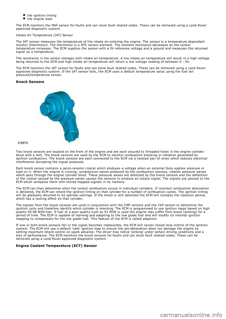
Two knock sens ors are located on the front of t he engi ne and are each s ecured to threaded holes in t he engine cylinderblock wit h a bol t. The knock sens ors are us ed by t he ECM t o monit or combus ti on knocking or vibrati on generat ed byignit ion combus ti on. The knock s ens ors are each connected t o t he ECM via a t wis t ed pai r of wires which reduces electricalint erference di s rupti ng t he si gnal produced.
Each knock s ens or cont ains a pei zo-ceramic crys t al whi ch produces a vol tage when an ext ernal force appli es pres s ure orload on it . W hen t he engi ne is runni ng, compres s ion waves produced by t he combus t ion proces s, creat es pres sure waveswhich pas s t hrough the engine cyli nder bl ock. Thes e press ure waves are detected by the knock s ens ors and the defl ect ionof the crys t al caus ed by the pres sure waves caus es the sens ors t o produce an out put s ignal. The s i gnals are pas s ed to theECM whi ch compares them wit h s tored mapped s ignal s i n it s memory.
The ECM can t hen det ermine when t he correct combus t ion occurs i n indivi dual cyl inders . If incorrect combus t ion detonat ionis det ect ed, the ECM can retard t he ignit ion ti ming on that cyl inder for a number of combus ti on cycl es . The i gni ti on ti mingwil l be gradually ret urned t o it s opti mal s et t ings. If t he knock is st il l det ected the ECM wi ll i ncreas e t he i nject ion period,which has a cooli ng effect on t hat cyl inder.
The s ignals from the knock s ens ors are us ed i n conjunct ion wi th the CMP sens ors and t he CKP s ens or t o det ermi ne theignit ion cycle and t herefore i dent ify which cylinder is knocki ng. The ECM is programmed to us e i gni ti on maps bas ed on highqual it y 95-98 RO N fuel . If fuel of a poor qual it y s uch as 91 RON i s us ed the engi ne may s uffer from knock (pinking) for aperi od of ti me. The ECM is capable of l earning and adapti ng to the l ow grade fuel and wil l modi fy it s int ernal ignit ionmapping t o compens at e for t he low grade fuel . Thi s feat ure of t he ECM i s called adapt ion.
If one or bot h knock s ensors fai l or the s ignal becomes i mplaus ible, t he ECM wi ll cancel clos ed loop cont rol of t he ignit ions ys t em. The ECM wi ll us e a defaul t 's afe' ignit ion map to ens ure the pre-det onat ion does not damage the engine bys ett ing maxi mum retard cont rol on s park advance. The dri ver may not ice 'pinking' under certai n dri vi ng condi ti ons and alos s of performance. The ECM monit ors t he knock s ens ors for fault s and can st ore fault relat ed codes . Thes e can beret ri eved us i ng a Land Rover approved diagnos t ic s ys tem.
Engine Coolant Temperature (ECT) Sensor
Page 1206 of 3229
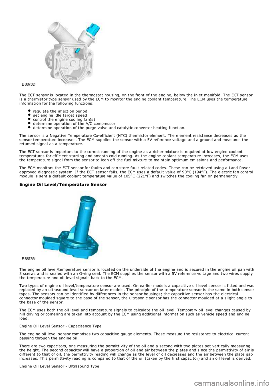
The ECT s ens or is locat ed i n t he thermost at hous ing, on t he front of the engine, below t he i nl et manifol d. The ECT s ens oris a t hermis t or type s ens or us ed by the ECM t o monit or the engine coolant t emperature. The ECM uses t he t emperatureinformat ion for the foll owi ng functi ons:
regulat e t he inject ion peri ods et engi ne idle target s peedcont rol t he engi ne cool ing fan(s )determine operat ion of t he A/C compres sordetermine operat ion of t he purge valve and catal yt ic convert er heat ing funct ion.
The s ens or is a Negat ive Temperat ure Co-efficient (NTC) thermis tor element . The element res is t ance decreas es as thes ens or t emperature increas es. The ECM suppli es the sens or wit h a 5V reference volt age and a ground and meas ures theret urned s ignal as a t emperature.
The ECT s ens or is important to the correct running of t he engi ne as a richer mixt ure i s required at low engi ne cool antt emperatures for efficient s tarti ng and s mooth cold running. As t he engi ne cool ant temperat ure i ncreas es , the ECM usest he temperat ure si gnal from the sens or to l ean off t he fuel mi xt ure to maint ai n optimum emis s ions and performance.
The ECM moni tors the ECT sens or for faul ts and can s t ore faul t rel at ed codes . These can be ret ri eved us ing a Land Roverapproved diagnos t ic s yst em. If the ECT sens or fail s, t he ECM us es a defaul t val ue of 90°C (194°F). The electric fan cont rolmodule i s s ent a default coolant temperat ure val ue of 105°C (221°F) and s wit ches t he cooling fan on permanent ly.
Engine Oil Level/Temperature Sensor
The engi ne oil l evel/t emperature s ens or is locat ed on t he unders ide of t he engi ne and is secured i n t he engi ne oil pan wi th3 s crews and i s s eal ed wi th an O-ring s eal. The ECM suppli es the s ens or wit h a 5V reference volt age and two wires s uppl yt he temperat ure and oi l level si gnal s back t o t he ECM.
Two t ypes of engine oi l level /t emperat ure s ensor are us ed. On earli er model s a capacit ive oi l level s ens or i s fit ted and wasrepl aced by an ul trasound l evel s ens or on l at er models . The principl e of the temperat ure s ens or i s t he s ame in bot h s ens ort ypes . The sens ors can be i dent ified by di fferences in t he s ens or housi ngs ; t he capacit ive s ensor has t he electricalconnector moulded s quare t o t he bas e of the s ens or, t he ult ras oni c s ens or has the connect or moulded at a s li ght angle tot he bas e of t he s ens or.
The ECM us es both the oi l l evel and t emperature s ignals t o calculat e t he oil level. Temporary oil level changes caus ed byhil l driving or cornering are taken i nt o account by t he ECM us ing addit ional informat ion s uch as vehi cl e s peed and engi neload.
Engi ne Oi l Level Sens or - Capacit ance Type
The engi ne oil l evel s ens or compris es t wo capaci ti ve gauge el ement s . Thes e meas ure the resi s tance to elect rical currentpass i ng through t he engine oi l.
There are t wo capacit ors , one meas uring t he permit ti vi ty of t he oil and a second with t wo pl at es s et verti cal ly meas uri ngt he hei ght . The s econd capaci tor wil l have a proport ion of oil and ai r bet ween t he plates and s i nce t he permit ti vi ty of ai r isdifferent t o t hat of oi l, t he permi tt ivit y readi ng wil l change as t he level of oi l decreas es and the ai r between t he plat e gapincreas es. This permi tt ivit y readi ng is compared t o t hat of the oi l (t aken by t he first capaci tor) and an oil level is derived.
Engi ne Oi l Level Sens or - Ult ras ound Type
Page 1207 of 3229
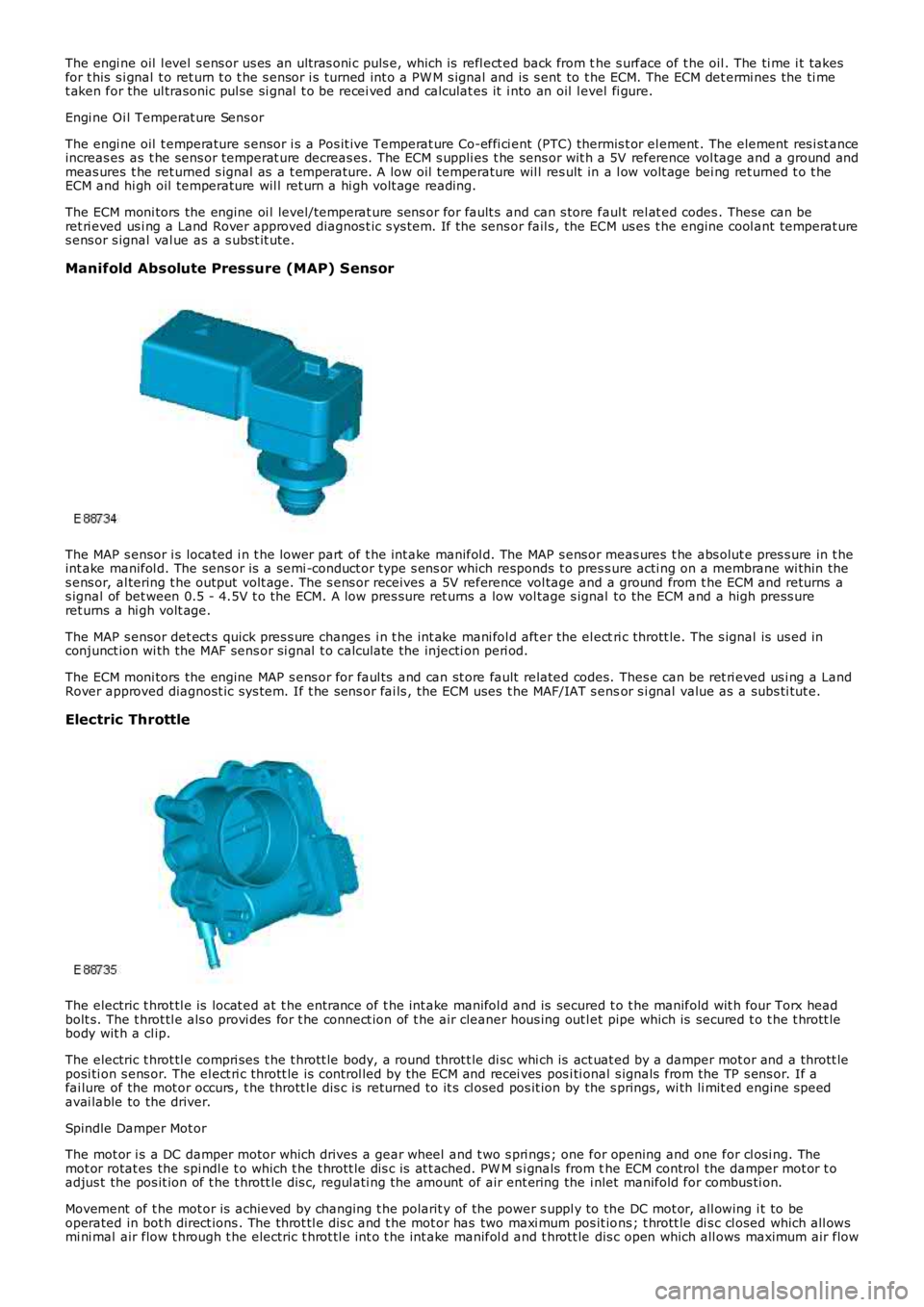
The engi ne oil l evel s ens or us es an ult ras oni c puls e, which is refl ect ed back from the s urface of t he oil . The ti me i t takesfor t his s i gnal t o ret urn t o t he s ensor i s turned int o a PW M s ignal and is s ent to the ECM. The ECM det ermi nes the ti met aken for the ul trasonic pul se si gnal t o be recei ved and calculat es it i nto an oil level fi gure.
Engi ne Oi l Temperat ure Sens or
The engi ne oil t emperature s ensor i s a Pos it ive Temperat ure Co-effi ci ent (PTC) thermis t or el ement . The element res i st anceincreas es as t he sens or temperat ure decreas es. The ECM s uppli es t he sens or wit h a 5V reference vol tage and a ground andmeas ures t he ret urned s ignal as a t emperature. A low oil temperature wil l res ult in a l ow volt age bei ng ret urned t o t heECM and hi gh oil temperature wil l ret urn a hi gh volt age reading.
The ECM moni tors the engine oi l level/temperat ure sens or for fault s and can s tore faul t rel at ed codes . These can beret ri eved us i ng a Land Rover approved diagnos t ic s ys tem. If the sens or fail s , the ECM us es t he engine cool ant temperat ures ens or s ignal val ue as a s ubst it ute.
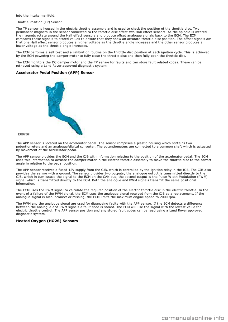
Manifold Absolute Pressure (MAP) Sensor
The MAP s ensor i s located i n t he lower part of t he int ake manifol d. The MAP s ens or meas ures t he abs olut e pres s ure in t heint ake manifol d. The sens or is a semi -conduct or type s ens or which responds t o pres s ure acti ng on a membrane wi thin thes ens or, al tering t he output volt age. The s ens or receives a 5V reference vol tage and a ground from t he ECM and returns as ignal of bet ween 0.5 - 4.5V t o t he ECM. A low pres sure ret urns a low vol tage s ignal to the ECM and a high press ureret urns a hi gh volt age.
The MAP s ensor det ect s quick pres s ure changes i n t he int ake mani fol d aft er the el ectri c thrott le. The s ignal is us ed inconjunct ion wi th the MAF sens or si gnal t o calculate the injecti on peri od.
The ECM moni tors the engine MAP s ens or for faul ts and can st ore fault related codes. Thes e can be ret ri eved us i ng a LandRover approved diagnost ic sys tem. If t he s ens or fai ls , the ECM uses t he MAF/IAT s ensor s i gnal value as a subs ti tut e.
Electric Throttle
The electric t hrot tl e is locat ed at t he entrance of t he int ake manifol d and is secured t o t he manifold wit h four Torx headbolt s. The t hrot tl e als o provi des for t he connect ion of t he air cleaner hous ing out let pipe which is secured t o t he t hrott lebody wit h a cl ip.
The electric t hrot tl e compri ses t he t hrott le body, a round throt t le di sc whi ch is act uat ed by a damper mot or and a thrott leposi ti on s ens or. The el ect ri c thrott le is control led by the ECM and recei ves pos i ti onal s ignals from the TP s ens or. If afai lure of the mot or occurs , t he thrott le di s c is returned to it s cl osed pos it ion by the s prings, wi th li mit ed engine s peedavai lable to the driver.
Spindle Damper Mot or
The mot or i s a DC damper motor which drives a gear wheel and t wo s pri ngs ; one for opening and one for cl osi ng. Themot or rotat es the spi ndl e t o which t he t hrott le dis c is at t ached. PW M s i gnals from the ECM control the damper mot or t oadjus t the pos it ion of t he t hrott le dis c, regul ati ng the amount of air ent ering the i nlet manifold for combus ti on.
Movement of t he mot or is achieved by changing t he polarit y of the power s uppl y to the DC mot or, all owing i t to beoperated in bot h direct ions . The throt tl e dis c and t he mot or has two maxi mum pos it ions ; t hrott le di s c cl osed which all owsmi ni mal air flow t hrough t he electric t hrot tl e int o t he int ake manifol d and t hrott le dis c open which all ows maximum air flow
Page 1208 of 3229
int o t he int ake manifol d.
Throt tl e Posi ti on (TP) Sensor
The TP s ensor i s hous ed i n t he elect ric t hrott le ass embly and is us ed t o check t he posi ti on of the throt t le di sc. Twopermanent magnet s i n t he sens or connect ed t o t he thrott le di sc affect t wo Hall effect sens ors . As t he s pi ndl e i s rot atedt he magnet s rot ate around t he Hall effect s ensors and produce offset analogue s ignals back t o t he ECM. The ECMcompares t hes e s ignals to st ored values t o ens ure t hat they s how an accurate throt tle dis c pos it ion. The offset s i gnals aret hat one Hal l effect s ens or produces a higher vol tage as t he t hrott le angl e increas es and the ot her sens or produces alower volt age as the throt tl e angle i ncreases .
The ECM performs a s elf t est and a cal ibrat ion routi ne on the throt t le di sc pos it ion at each igni ti on cycle. This i s achi evedby t he ECM poweri ng the damper mot or to full y clos e t he throt t le di sc and then ful ly open t he t hrott le dis c.
The ECM moni tors the DC damper motor and t he TP s ens or for faul ts and can st ore fault related codes. Thes e can beret ri eved us i ng a Land Rover approved diagnos t ic s ys tem.
Accelerator Pedal Position (APP) Sensor
The APP s ens or is locat ed on t he accel erator pedal . The s ens or compris es a pl ast ic hous ing whi ch cont ai ns t wopotenti ometers and an analogue/digit al convert er. The potent iomet ers are connect ed to a common shaft which is act uat edby movement of the accel erator pedal.
The APP s ens or provides t he ECM and t he CJB wi th i nformati on rel at ing to t he pos it ion of t he accelerat or pedal . The ECMus es this informati on t o act uate the damper mot or i n t he electric t hrot tl e as sembl y t o move t he thrott le di sc to the correctangl e i n rel ati on to the pedal pos it ion.
The APP s ens or receives a fus ed 12V s upply from t he CJB, whi ch is controll ed by the ignit ion relay in the BJB. The CJB als oprovides t he s ens or wit h a ground. The s ens or provi des two out puts ; t he anal ogue output i s t rans mit ted di rectl y t o t heCJB, whi ch in t urn is s ues the s ignal to the ECM on t he CAN bus , the s econd out put is t he Puls e W idth Modul ati on (PW M)s ignal whi ch is trans mi tt ed direct ly to t he ECM. Both the analogue and PW M s ignals trans mi t the s ame pos it ionalinformat ion.
The ECM us es t he PW M si gnal t o calcul ate the requi red pos it ion of t he electric t hrottl e dis c i n t he electric t hrot tl e. In t heevent of a fail ure of t he PW M si gnal , the ECM uses the analogue s ignal recei ved from t he CJB as a replacement . If t heanal ogue si gnal i s als o i ncorrect or mis s ing, the ECM li mit s t he maximum engi ne s peed to 2000 rpm.
The PW M and the analogue s ignal are us ed for di agnos ing fault s wit h t he APP s ensor. If t he ECM det ect s a di fferencebetween t he analogue and PW M si gnal s a faul t code is s t ored. The ECM wil l use the s ignal wi th t he l owes t value forelectric t hrot tl e cont rol . The APP s ens or pos i ti on and any st ored fault codes can be read us ing a Land Rover approveddiagnost ic s ys tem.
Heated Oxygen (HO2S) Sensors