Page 1269 of 3229
Publi s hed: 11-May-2011
Electronic Engine Controls - TD4 2.2L Diesel - Fuel Temperature Sensor
Removal and Inst all ati on
Removal
• W ARNINGS: Avoid flames , s parks or li ght ed s ubs t ances .
W ai t for a mini mum of 1 minute aft er the engine has s t opped before carryi ng out any
repair t o t he fuel inject ion
s ys t em.
Remove t he cover and dis connect the bat tery ground cabl e.
Refer t o: Specificati ons (414-00 Bat tery and Charging Sys tem -
General Informat ion, Specificati ons).
1.
Remove t he engi ne cover.
Refer t o: Engi ne Cover - TD4 2.2L Dies el (501-05 Interior Tri m and
Ornament ati on, Removal and Ins tal lat ion).
2. T orque:
10 Nm 3.
4.
Page 1271 of 3229
Publi s hed: 11-May-2011
Electronic Engine Controls - TD4 2.2L Diesel - Oil Temperature Sensor
Removal and Inst all ati on
Removal
• NOTE: Removal s t eps in t his procedure may cont ain i nst all ati on det ail s.
Remove t he cover and dis connect the bat tery ground cabl e.
Refer t o: Specificati ons (414-00 Bat tery and Charging Sys tem -
General Informat ion, Specificati ons).
1.
Remove t he s tart er mot or.
Refer t o: Start er Motor (303-06B Starti ng Sys t em - TD4 2.2L Dies el,
Removal and Ins tall ati on).
2. 3. CAUTION: Make s ure that a new s eali ng was her
i s ins tal led.
T orque: 27 Nm 3.
Installation To i nst all , revers e t he removal procedure.
1.
Check and top-up the engine oi l if required.
2.
Page 1274 of 3229
Publi s hed: 11-May-2011
Electronic Engine Controls - TD4 2.2L Diesel - Exhaust Gas Temperature
Sensor
Removal and Inst all ati on
Removal
W ARNING: Observe due care when worki ng near a hot exhaust s ys tem.
• NOTE: Removal s t eps in t his procedure may cont ain i nst all ati on det ail s.
1. W ARNING: Do not work on or under a vehi cle s upported onl yby a jack. Al ways support t he vehi cl e on s afet y s tands .
Rais e and s upport t he vehi cl e.
1.
Remove t he engi ne cover.
Refer t o: Engi ne Cover - 2.2L Dies el (501-05, Removal andInst all at ion).
2.
3.
Page 1276 of 3229
Publi s hed: 11-May-2011
Electronic Engine Controls - TD4 2.2L Diesel - Diesel Particulate Filter (DPF)
Temperature Sensor
Removal and Inst all ati on
Removal W ARNING: Observe due care when worki ng near a hot exhaust s ys tem.
• NOTE: Removal s t eps in t his procedure may cont ain i nst all ati on det ail s.
1. W ARNING: Do not work on or under a vehi cle s upported onl y
by a jack. Al ways support t he vehi cl e on s afet y s tands .
Rais e and s upport t he vehi cl e.
1. 2.
3. CAUTION: Before dis connecti ng or removing t he
component s, make sure t he area around t he joi nt faces
and connecti ons are clean. Plug open connecti ons to
prevent cont aminati on.
T orque: 35 Nm 3.
Installation Apply ant i-sei ze compound t o t he s ens or threads .
Refer t o: Specificati ons (303-08, Speci ficat ions).
1.
To i nst all , revers e t he removal procedure.
2.
Page 1281 of 3229

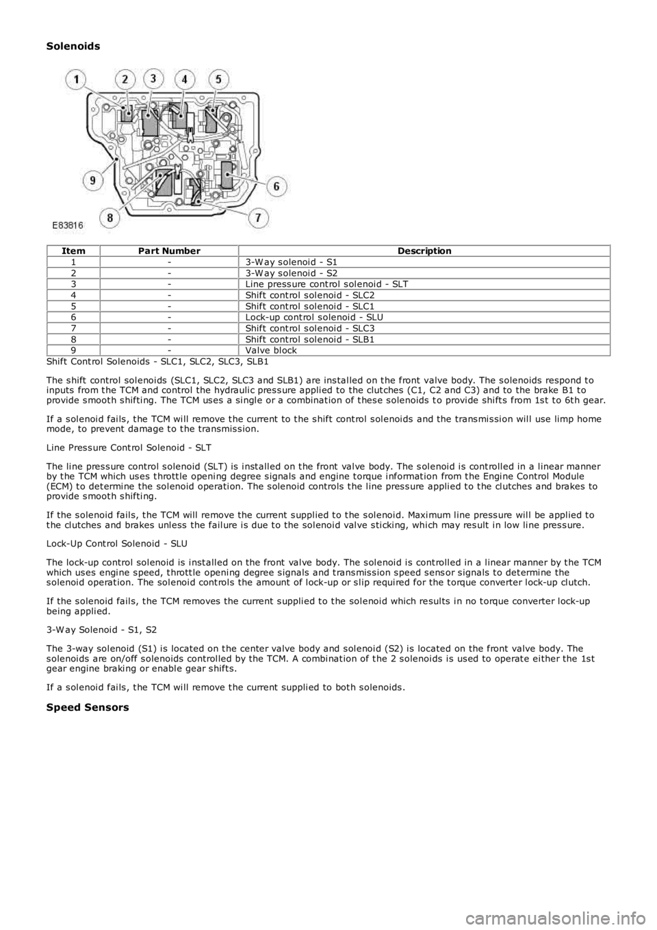
Solenoids
ItemPart NumberDescription
1-3-W ay s olenoi d - S1
2-3-W ay s olenoi d - S23-Line press ure cont rol s ol enoi d - SLT
4-Shift cont rol s ol enoi d - SLC2
5-Shift cont rol s ol enoi d - SLC16-Lock-up cont rol s olenoi d - SLU
7-Shift cont rol s ol enoi d - SLC3
8-Shift cont rol s ol enoi d - SLB19-Valve bl ock
Shift Cont rol Solenoids - SLC1, SLC2, SLC3, SLB1
The s hift control sol enoi ds (SLC1, SLC2, SLC3 and SLB1) are ins tal led on t he front valve body. The s olenoids respond t oinputs from t he TCM and control the hydrauli c pres s ure appli ed to the clut ches (C1, C2 and C3) and to the brake B1 t oprovide s moot h s hifti ng. The TCM us es a si ngl e or a combinat ion of t hes e s olenoids to provi de shi ft s from 1s t t o 6t h gear.
If a s ol enoi d fai ls , t he TCM wi ll remove t he current t o t he s hift cont rol s ol enoi ds and the trans mi s si on wil l use limp homemode, to prevent damage t o t he transmis s ion.
Line Pres s ure Cont rol Solenoid - SLT
The li ne pres s ure control s olenoid (SLT) is i nst all ed on t he front val ve body. The sol enoi d i s cont roll ed in a l inear mannerby t he TCM which us es t hrott le openi ng degree s ignals and engine t orque i nformat ion from t he Engi ne Control Module(ECM) t o det ermi ne the sol enoid operati on. The s olenoid controls t he l ine pres s ure appli ed t o t he cl utches and brakes toprovide s moot h s hifti ng.
If the s olenoid fail s, t he TCM will remove the current s uppl ied t o t he s ol enoi d. Maxi mum l ine press ure wil l be appl ied t ot he cl utches and brakes unl ess the fail ure i s due t o the sol enoi d val ve s ti cki ng, whi ch may res ult i n low li ne pres s ure.
Lock-Up Cont rol Solenoid - SLU
The lock-up control sol enoid is i nst all ed on t he front val ve body. The s ol enoi d i s cont roll ed in a l inear manner by t he TCMwhich us es engi ne s peed, t hrott le openi ng degree s ignals and t rans mis s ion s peed s ensor s ignals t o det ermi ne thes olenoi d operat ion. The sol enoi d cont rol s the amount of l ock-up or s l ip requi red for the t orque converter l ock-up cl utch.
If the s olenoid fail s, t he TCM removes the current s uppli ed t o t he sol enoi d which resul ts i n no t orque converter l ock-upbeing appli ed.
3-W ay Solenoi d - S1, S2
The 3-way sol enoid (S1) i s located on t he center valve body and s ol enoi d (S2) i s located on the front valve body. Thes olenoi ds are on/off s olenoids control led by the TCM. A combi nat ion of t he 2 s olenoids i s us ed to operat e ei ther the 1s tgear engine braki ng or enabl e gear s hift s.
If a s ol enoi d fai ls , t he TCM wi ll remove t he current s uppli ed to bot h s olenoids .
Speed Sensors
Page 1282 of 3229

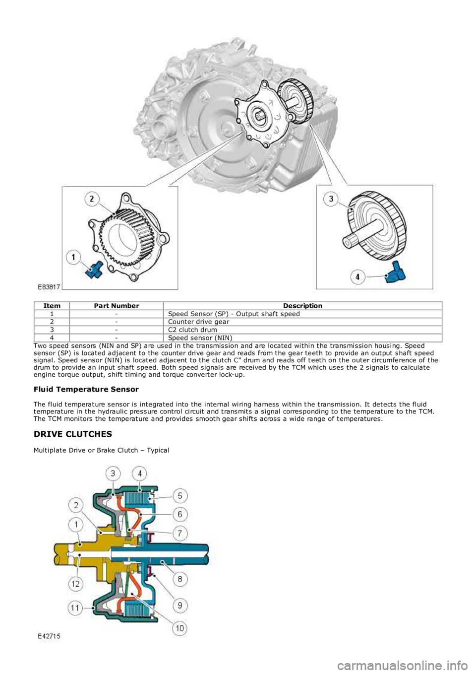
ItemPart NumberDescription
1-Speed Sens or (SP) - Output s haft s peed2-Count er drive gear
3-C2 clutch drum
4-Speed s ensor (NIN)Two s peed s ens ors (NIN and SP) are us ed i n t he transmis s ion and are located wi thi n the trans mi s si on hous i ng. Speeds ens or (SP) i s located adjacent to the counter dri ve gear and reads from t he gear teeth to provide an out put s haft s peeds ignal. Speed sens or (NIN) is locat ed adjacent to t he clut ch C" drum and reads off teet h on the out er circumference of t hedrum to provide an i nput s haft s peed. Bot h s peed s ignal s are received by t he TCM which us es t he 2 s ignals to calculat eengi ne t orque output, s hift t imi ng and torque convert er lock-up.
Fluid Temperature Sensor
The fl uid t emperat ure s ens or i s int egrated into the internal wi ri ng harness wit hin the t rans mis s ion. It det ect s t he fl uidt emperature in the hydrauli c pres s ure control ci rcuit and t rans mit s a s i gnal corres pondi ng t o the temperat ure to t he TCM.The TCM moni tors the temperat ure and provi des smoot h gear s hi ft s acros s a wi de range of t emperatures.
DRIVE CLUTCHES
Mult ipl at e Drive or Brake Cl utch – Typical
Page 1318 of 3229
Publi s hed: 11-May-2011
Automatic Transmission/Transaxle - Input Shaft Speed (ISS) SensorI6 3.2L
Petrol
Removal and Inst all ati on
Removal CAUTION: Extreme cleanli nes s mus t be exercis ed when handli ng thes e component s.
• NOTE: Removal s t eps in t his procedure may cont ain i nst all ati on det ail s.
1. W ARNING: Make sure t o s upport the vehicle wit h axle
s tands .
Rais e and s upport t he vehi cl e.
1.
Remove t he val ve body.
Refer t o: Main Cont rol Valve Body (307-01 Aut omat ic
Trans mi ss ion/Transaxle, Removal and Ins tal lati on).
2. 3. CAUTION: Extreme cleanli nes s mus t be
exercis ed when handl ing t his component .
T orque: 6 Nm 3.
Installation To i nst all , revers e t he removal procedure.
1.
Page 1370 of 3229

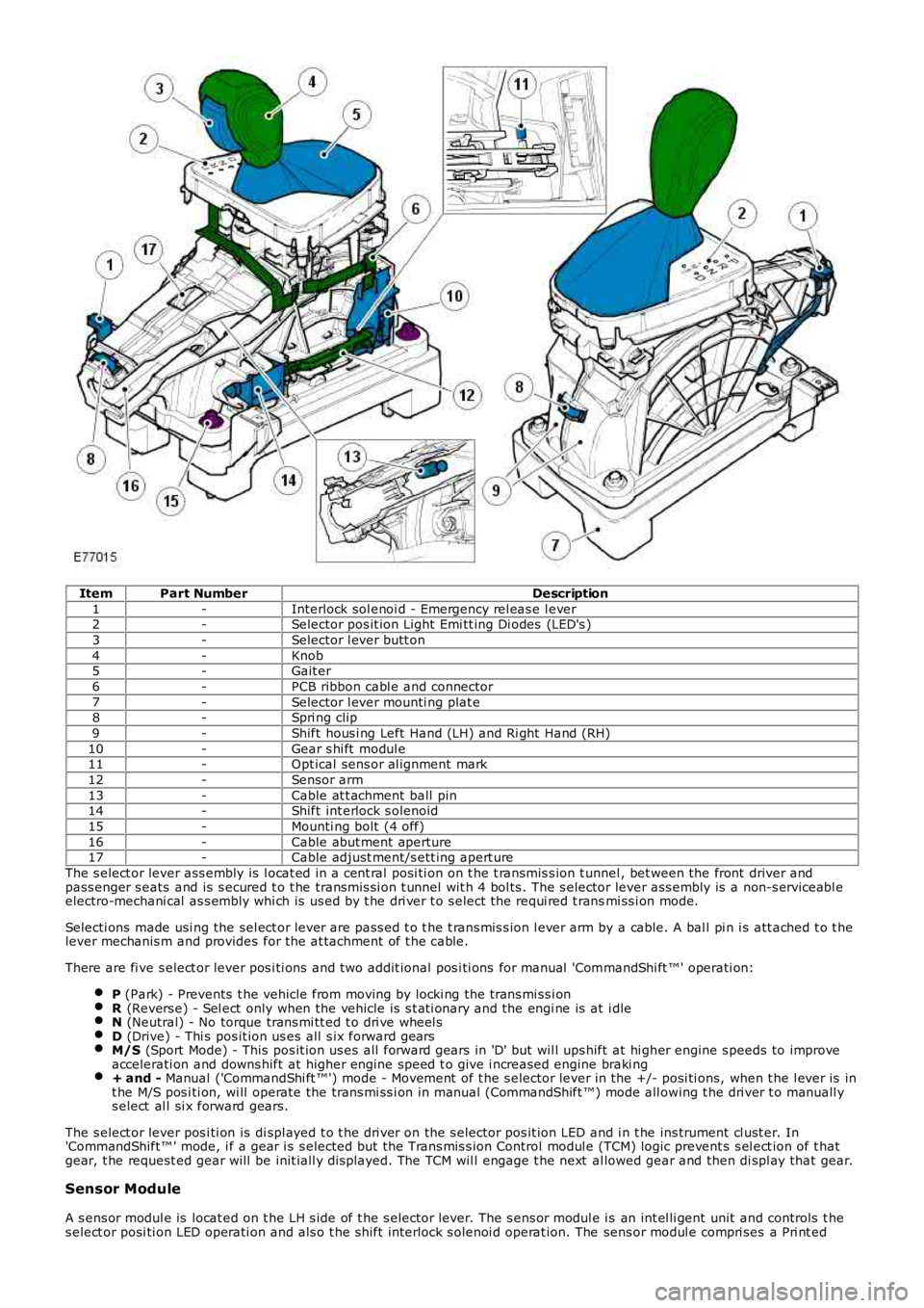
ItemPart NumberDescription
1-Interlock sol enoi d - Emergency rel eas e l ever2-Selector pos it ion Light Emi tt ing Di odes (LED's )
3-Selector l ever butt on
4-Knob5-Gait er
6-PCB ribbon cabl e and connector
7-Selector l ever mounti ng plat e8-Spri ng clip
9-Shift hous i ng Left Hand (LH) and Ri ght Hand (RH)
10-Gear s hi ft modul e11-Opt ical sens or al ignment mark
12-Sensor arm
13-Cable at t achment ball pin14-Shift int erlock s olenoid
15-Mounti ng bolt (4 off)
16-Cable abut ment aperture17-Cable adjust ment/s ett ing apert ure
The s elect or lever ass embly is l ocat ed in a cent ral posi ti on on t he t ransmis s ion t unnel , bet ween the front driver andpass enger s eats and is s ecured t o t he transmis si on t unnel wit h 4 bol ts . The s elector lever ass embly is a non-s erviceabl eelectro-mechani cal as s embly whi ch is us ed by t he dri ver t o s elect the requi red t ransmi ss i on mode.
Selecti ons made usi ng the sel ect or lever are pass ed t o t he t rans mis s ion l ever arm by a cable. A bal l pi n i s att ached t o t helever mechanis m and provides for the at tachment of t he cable.
There are fi ve s elect or lever pos i ti ons and t wo addit ional pos i ti ons for manual 'CommandShi ft ™' operati on:
P (Park) - Prevents t he vehicle from moving by locki ng the trans mi ss i onR (Revers e) - Sel ect only when the vehicle is s t ati onary and the engi ne is at i dleN (Neutral) - No torque trans mi tt ed t o dri ve wheel sD (Drive) - Thi s pos it ion us es all s ix forward gearsM/S (Sport Mode) - This pos it ion us es all forward gears in 'D' but wil l ups hift at hi gher engine s peeds to improveaccelerati on and downs hift at higher engine speed t o give i ncreased engine braki ng+ and - Manual ('CommandShi ft ™') mode - Movement of t he s elector lever in the +/- posi ti ons, when t he l ever is int he M/S pos i ti on, wi ll operate the trans mi ss i on in manual (CommandShift ™) mode all owing t he dri ver t o manuall ys elect al l si x forward gears.
The s elect or lever pos i ti on is di spl ayed t o t he dri ver on the s elector pos it ion LED and i n t he ins trument cl ust er. In'CommandShift™ ' mode, i f a gear i s s elected but t he Trans mis s ion Control modul e (TCM) logic prevent s s el ect ion of t hatgear, t he request ed gear will be init iall y dis played. The TCM wil l engage t he next al lowed gear and then di spl ay that gear.
Sensor Module
A s ens or modul e is locat ed on t he LH s ide of t he s elector lever. The s ens or modul e is an int el li gent unit and controls t hes elect or posi ti on LED operati on and als o t he s hift interlock s olenoi d operat ion. The sens or modul e compri ses a Pri nt ed