2006 LAND ROVER FRELANDER 2 sensor
[x] Cancel search: sensorPage 1392 of 3229
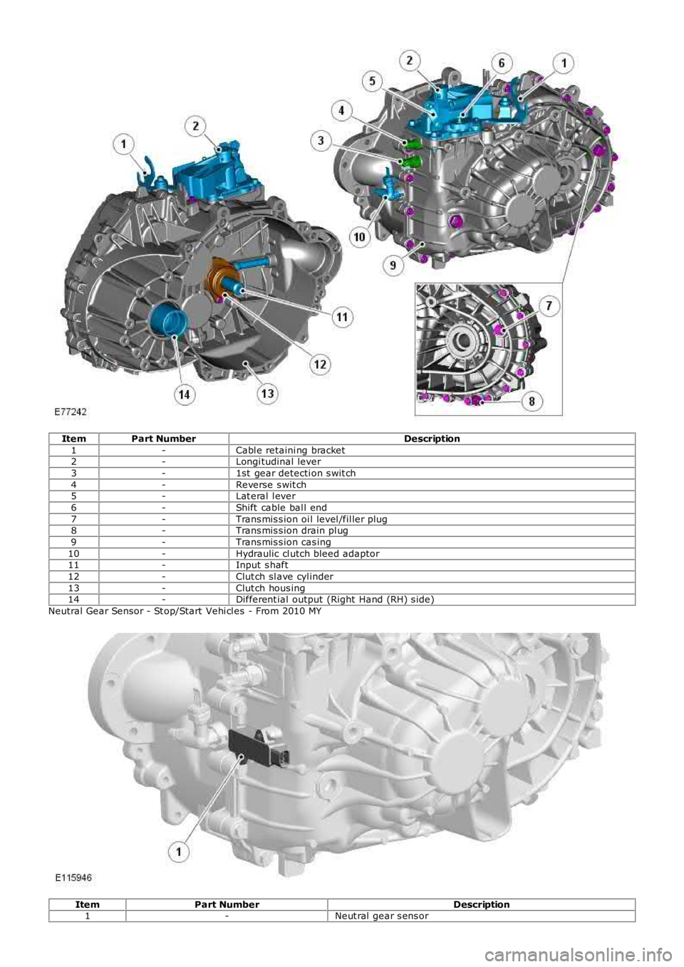
ItemPart NumberDescription
1-Cabl e retaini ng bracket2-Longi tudinal lever
3-1st gear detecti on s wit ch
4-Reverse s wit ch5-Lat eral l ever
6-Shift cable bal l end
7-Trans mis s ion oi l level /fil ler plug8-Trans mis s ion drain pl ug
9-Trans mis s ion cas ing
10-Hydraulic cl utch bleed adaptor11-Input s haft
12-Clut ch sl ave cyl inder
13-Clut ch hous ing14-Different ial output (Right Hand (RH) s ide)
Neutral Gear Sensor - St op/Start Vehi cl es - From 2010 MY
ItemPart NumberDescription1-Neut ral gear s ens or
Page 1393 of 3229
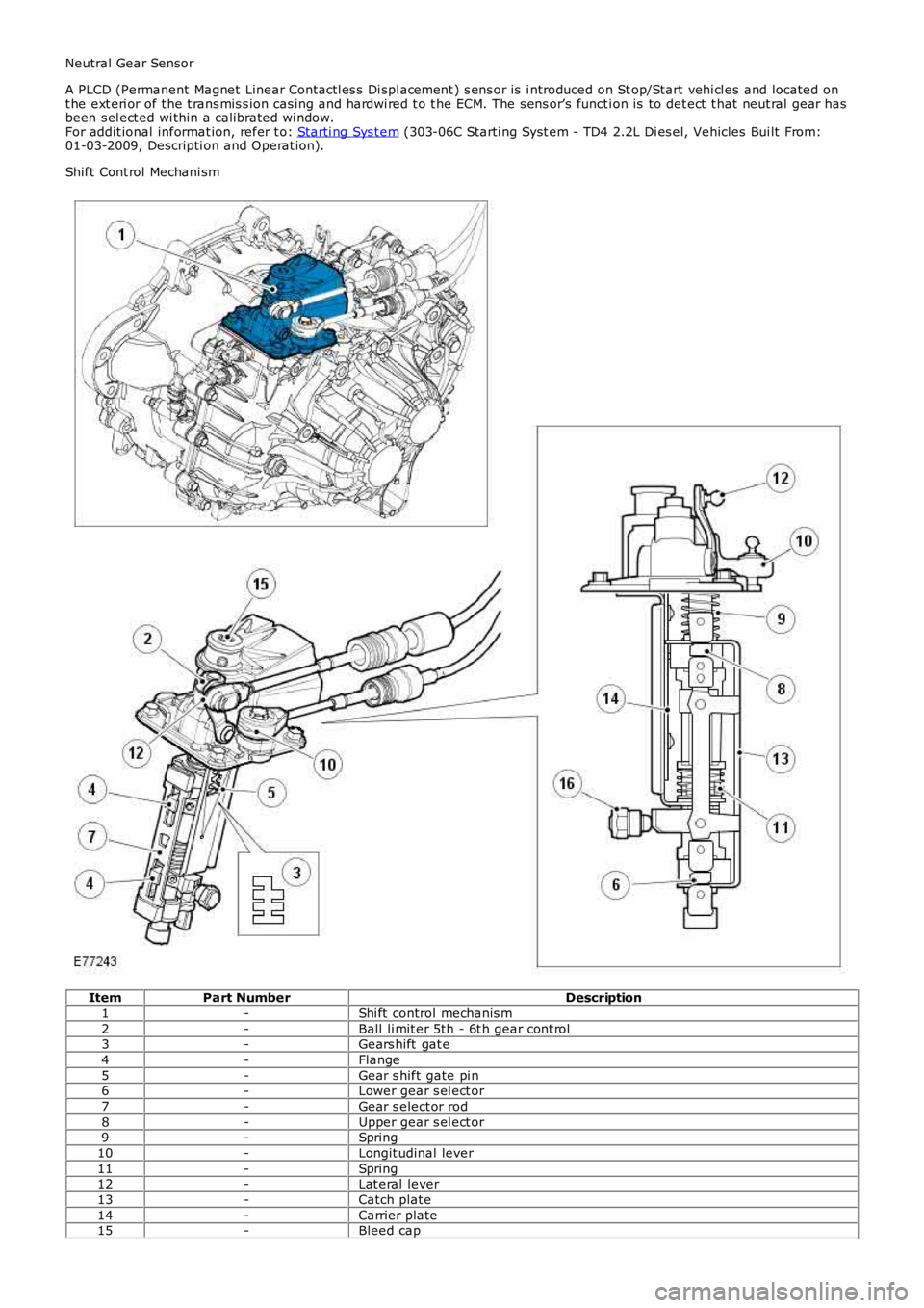
Neutral Gear Sensor
A PLCD (Permanent Magnet Linear Contactl es s Di s pl acement ) s ens or is i ntroduced on Stop/Start vehi cl es and located ont he ext eri or of t he t rans mis s ion cas ing and hardwi red t o t he ECM. The s ens or’s functi on is to det ect t hat neut ral gear hasbeen s el ect ed wi thin a calibrated wi ndow.For addit ional informat ion, refer t o: Starti ng Sys t em (303-06C Starti ng Syst em - TD4 2.2L Di es el, Vehicles Bui lt From:01-03-2009, Descripti on and Operat ion).
Shift Cont rol Mechani sm
ItemPart NumberDescription
1-Shi ft control mechanis m
2-Ball li mit er 5th - 6t h gear cont rol3-Gears hift gat e
4-Flange
5-Gear s hift gate pi n6-Lower gear s el ect or
7-Gear s elect or rod
8-Upper gear s el ect or9-Spring
10-Longit udinal lever
11-Spring12-Lat eral lever
13-Catch plat e
14-Carrier plate15-Bleed cap
Page 1416 of 3229
which i s hydraulicall y act uated from t he cl utch pedal.
Pres s ing t he clutch pedal pres surizes t he hydraul ic fluid in the mas t er cyli nder. The fl uid pres s ure is t rans ferred via a pipefrom the mas t er cyli nder t o t he s lave cyl inder in the t rans mis s ion. The fluid press ure operates t he s lave cylinder which i nt urn pus hes the fingers of t he clut ch cover, rel easi ng the driven pl at e and di sengagi ng t he dri ve from t he engi ne crankshaftt o the trans mi s si on.
A hydrauli c clutch bl eed adapt or i s l ocated on the front of t he transmis s ion. The adapt or provi des the connect ion betweent he pres sure pipe from t he mas ter cyl inder to the s l ave cyli nder. The adapt or contains a bleed s crew to purge t he cl utchhydraulic sys tem of air aft er s ervice repl acement of one of the hydrauli c components. The adaptor als o i ncl udes a peakt orque li mit er. This prevent s ins t ant clut ch engagement if t he dri ver accident all y rel eas es t he clutch l ever t o preventdamage to the driveli ne components .
Stop/Start Vehicles - From 2010 MY
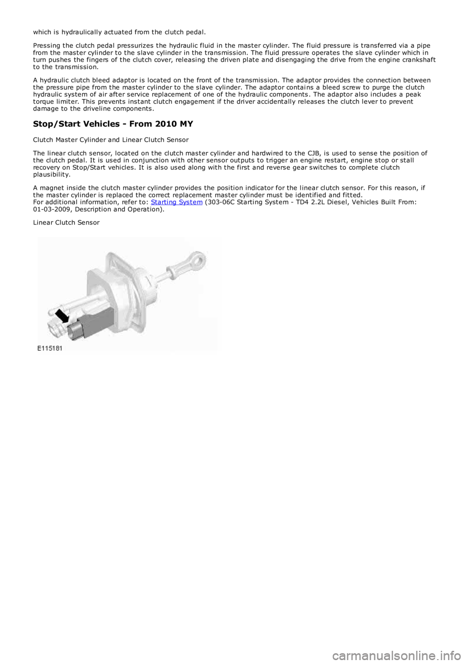
Clut ch Mast er Cyl inder and Linear Cl utch Sensor
The li near clut ch s ens or, l ocat ed on t he cl utch mas t er cyli nder and hardwi red t o t he CJB, i s us ed to s ens e t he posi ti on oft he cl utch pedal. It is us ed in conjunct ion wi th ot her sens or out puts t o t ri gger an engine res tart, engine s t op or st allrecovery on St op/Start vehi cl es. It is al s o us ed along wit h t he first and revers e gear s wi tches to compl ete cl ut chplaus ibil it y.
A magnet ins ide the clut ch mas ter cylinder provides t he posi ti on indicator for the linear cl utch s ensor. For t his reason, ift he mas ter cyl inder is replaced the correct replacement mas t er cyli nder mus t be i dent ified and fit t ed.For addit ional informat ion, refer t o: Starti ng Sys t em (303-06C Starti ng Syst em - TD4 2.2L Di es el, Vehicles Bui lt From:01-03-2009, Descripti on and Operat ion).
Linear Clutch Sens or
Page 1513 of 3229
Publi s hed: 11-May-2011
Exhaust System - I6 3.2L Petrol -
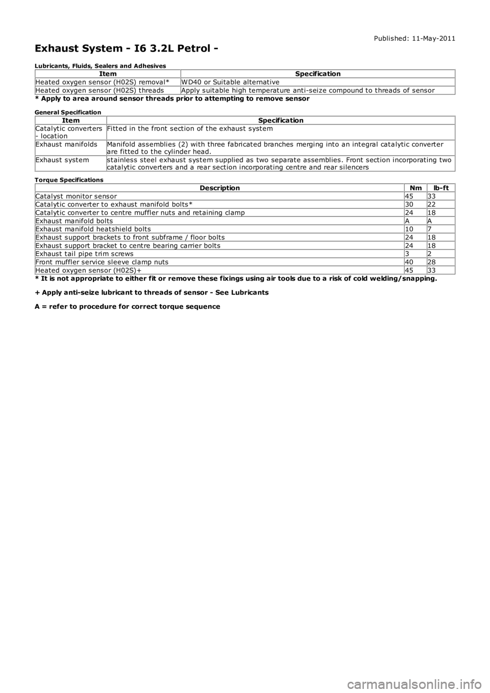
Lubricants, Fluids, Sealers and AdhesivesItemSpecification
Heated oxygen s ens or (H02S) removal*W D40 or Sui table al ternat ive
Heated oxygen s ens or (H02S) t hreadsApply s uit able hi gh temperat ure ant i-s ei ze compound t o t hreads of s ens or* Apply to area around sensor threads prior to attempting to remove sensor
General Specification
ItemSpecificationCatal yt ic convert ers- l ocat ionFi tt ed in the front s ect ion of t he exhaus t s yst em
Exhaus t manifoldsMani fold as s embli es (2) wi th three fabri cat ed branches mergi ng int o an int egral cat alyti c convert erare fit ted t o t he cyl inder head.
Exhaus t s yst ems t ainles s s teel exhaus t s ys t em s upplied as two separat e as sembl ies . Front s ect ion i ncorporat ing twocatal yt ic convert ers and a rear sect ion i ncorporat ing centre and rear s i lencers
Torque Specifications
DescriptionNmlb-ft
Catal ys t moni tor s ens or4533Catal yt ic convert er t o exhaus t mani fold bol ts *3022
Catal yt ic convert er t o centre muffl er nut s and ret aining cl amp2418
Exhaus t manifold bol tsAAExhaus t manifold heat shi el d bolt s107
Exhaus t s upport bracket s t o front subframe / floor bolt s2418
Exhaus t s upport bracket t o cent re bearing carrier bolt s2418Exhaus t t ai l pipe t ri m s crews32
Front muffl er s ervi ce sl eeve cl amp nuts4028
Heated oxygen s ens or (H02S)+4533* It is not appropriate to either fit or remove these fixings using air tools due to a risk of cold welding/snapping.
+ Apply anti-seize lubricant to threads of sensor - See Lubricants
A = refer to procedure for correct torque sequence
Page 1525 of 3229
Publi s hed: 11-May-2011
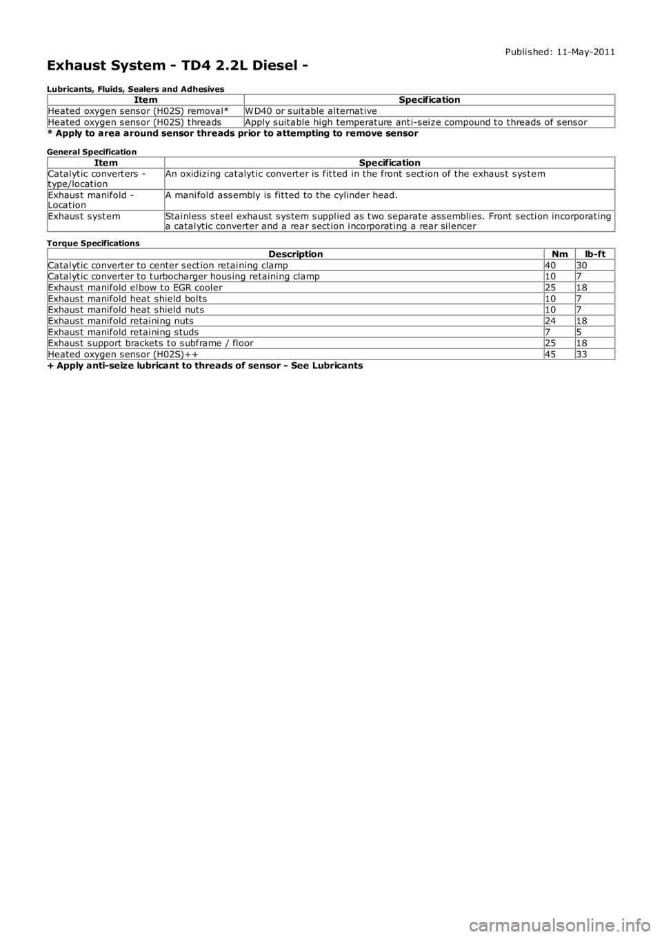
Exhaust System - TD4 2.2L Diesel -
Lubricants, Fluids, Sealers and AdhesivesItemSpecification
Heated oxygen s ens or (H02S) removal*W D40 or s uit able al ternat ive
Heated oxygen s ens or (H02S) t hreadsApply s uit able hi gh temperat ure ant i-s ei ze compound t o t hreads of s ens or* Apply to area around sensor threads prior to attempting to remove sensor
General Specification
ItemSpecificationCatal yt ic convert ers -t ype/locat ionAn oxidizi ng cat alyti c convert er is fit t ed in t he front s ect ion of t he exhaus t s ys t em
Exhaus t manifold -Locat ionA mani fold ass embly is fit ted to t he cylinder head.
Exhaus t s yst emStai nl ess st eel exhaust s ys tem s uppl ied as t wo s eparate ass embli es. Front s ecti on incorporat inga catal yt ic converter and a rear s ect ion i ncorporat ing a rear s il encer
Torque Specifications
DescriptionNmlb-ft
Catal yt ic convert er t o center s ect ion retai ning clamp4030Catal yt ic convert er t o t urbocharger hous ing retaini ng clamp107
Exhaus t manifold el bow t o EGR cool er2518
Exhaus t manifold heat s hield bol ts107Exhaus t manifold heat s hield nut s107
Exhaus t manifold retai ni ng nuts2418
Exhaus t manifold retai ni ng s tuds75Exhaus t s upport bracket s t o s ubframe / fl oor2518
Heated oxygen s ens or (H02S)++4533
+ Apply anti-seize lubricant to threads of sensor - See Lubricants
Page 1533 of 3229
DPF Air Management Module
The DPF air management modul e control s t he fol lowing funct ions :
EGR controlTurbocharger boos t pres sure cont rolInt ake air t emperature and pres s ure control.
Duri ng act ive regenerat ion, t he EGR operat ion i s dis abl ed and t he cl osed-loop acti vat ion of t he t urbocharger boostcont rol ler is calculat ed. The ai r management module cont rols the ai r in t he int ake manifol d t o a predet ermi ned level ofpres s ure and t emperat ure. Thi s cont rol i s required t o achi eve the correct i n-cylinder condi ti ons for s table and robustcombus t ion of t he post i njected fuel.
The module controls t he i nt ake air t emperature by actuati ng t he EGR t hrott le and by adjus tment of t he turbocharger boos tpres s ure control.
DPF Co-ordinator Module
The DPF co-ordi nat or module react s t o a regenerat ion reques t from the s upervis or module by i nit iat ing and co-ordi nat ingt he foll owing DPF regenerat ion reques t s :
EGR cut-offTurbocharger boos t pres sure cont rolEngi ne load i ncreaseControl of air press ure and temperat ure in t he i nt ake manifoldFuel i njecti on cont rol.
W hen t he s upervis or modul e i ss ues a regenerat ion reques t , the co-ordinator module reques t s EGR cut-off and aregenerat ion s peci fi c turbocharger boos t pres s ure control. It then wai ts for a feedback s ignal from t he EGR s ys t emconfirming that the EGR val ve is cl osed.
W hen t he EGR valve i s clos ed, t he co-ordi nator module i nit iat es reques t s t o increas e engine l oad by cont roll ing t he i nt akeair t emperature and pres s ure.
Once confirmati on is recei ved that int ake condit ions are cont rol led or a cali brati on t ime has expired, the co-ordinatormodule t hen changes t o a s t ate awai ti ng an accelerator pedal release manoeuver from t he dri ver. If t his occurs or acal ibrat ion ti me has expired, t he co-ordi nat or modul e generates a request t o control fuel injecti ons to increas e exhaus tgas temperature.
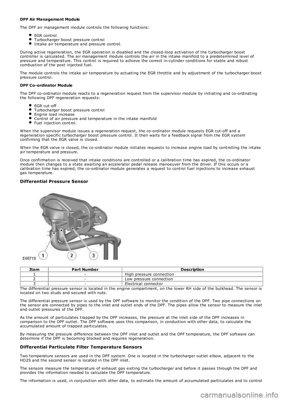
Differential Pressure Sensor
ItemPart NumberDescription
1-High press ure connect ion2-Low pres s ure connect ion
3-Electrical connect or
The different ial pres s ure s ensor i s located i n t he engi ne compart ment , on t he lower RH si de of the bul khead. The sens or islocated on two st uds and s ecured wit h nuts .
The different ial pres s ure s ensor i s us ed by the DPF software t o monit or the condit ion of t he DPF. Two pi pe connecti ons ont he sens or are connect ed by pipes t o t he inlet and out let ends of t he DPF. The pipes all ow t he s ens or to measure t he inletand outl et press ures of t he DPF.
As t he amount of parti culat es t rapped by the DPF increases , t he pres sure at t he inlet s i de of the DPF i ncreas es i ncomparis on t o t he DPF outl et . The DPF s oft ware us es t his compari son, in conduct ion wit h other data, t o calculate theaccumulat ed amount of trapped part iculat es.
By meas uri ng the press ure difference between t he DPF i nl et and out let and t he DPF t emperature, the DPF s oftware candetermine i f the DPF is becoming bl ocked and requires regenerat ion.
Differential Particulate Filter Temperature Sensors
Two t emperature s ensors are us ed i n t he DPF s ys t em. One is locat ed i n t he turbocharger out let el bow, adjacent to theHO2S and t he s econd s ensor i s located i n t he DPF inl et .
The s ens ors measure t he temperat ure of exhaust gas exit ing the t urbocharger and before i t pas s es t hrough the DPF andprovides t he informat ion needed to cal cul at e t he DPF t emperature.
The informat ion i s us ed, i n conjunct ion wi th other dat a, to est imat e t he amount of accumulat ed parti cul ates and t o control
Page 1548 of 3229
Publi s hed: 11-May-2011
Exhaust System - TD4 2.2L Diesel - Diesel Particulate Filter (DPF)
Differential Pressure Sensor
Removal and Inst all ati on
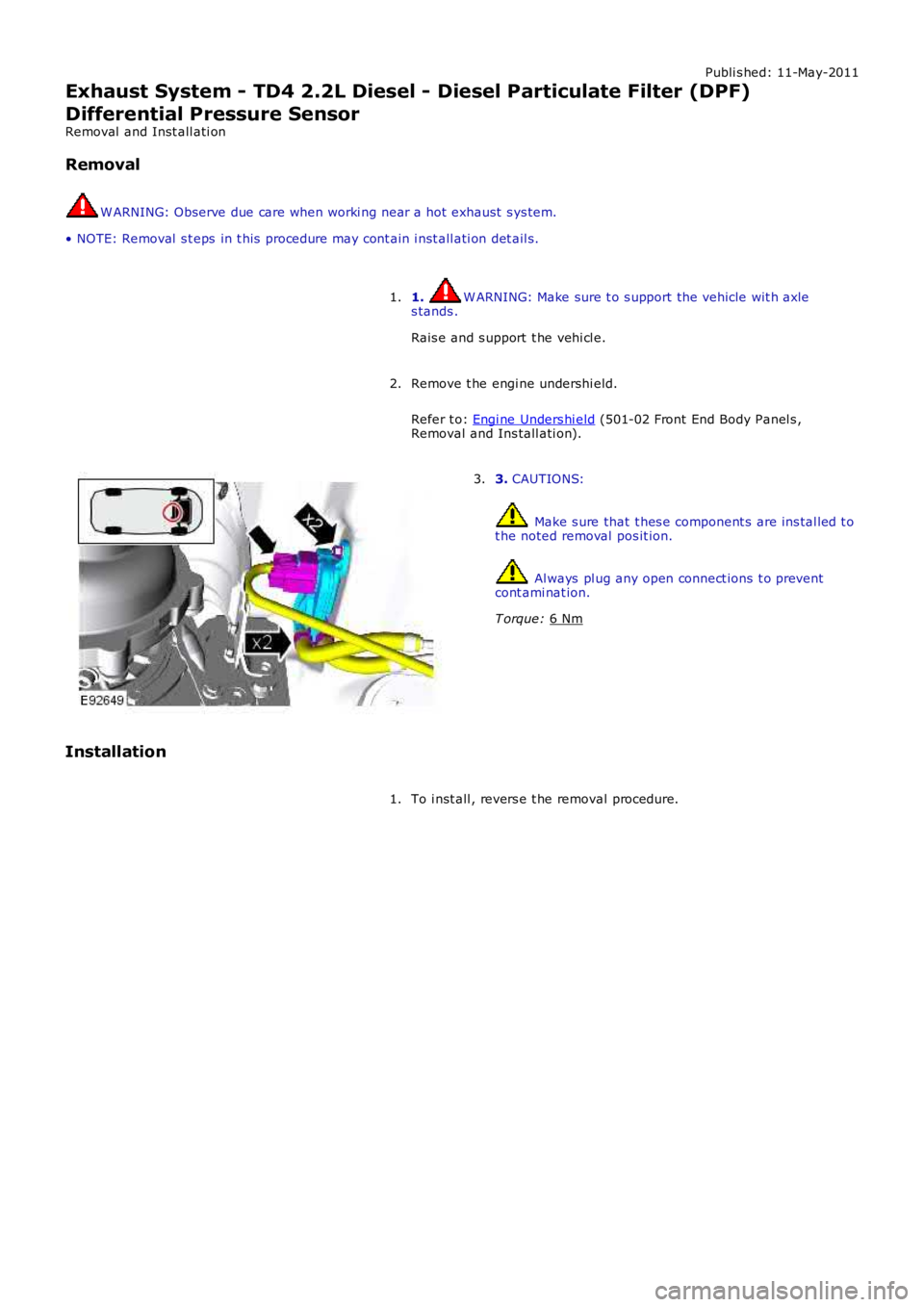
Removal W ARNING: Observe due care when worki ng near a hot exhaust s ys tem.
• NOTE: Removal s t eps in t his procedure may cont ain i nst all ati on det ail s.
1. W ARNING: Make sure t o s upport the vehicle wit h axle
s tands .
Rais e and s upport t he vehi cl e.
1.
Remove t he engi ne undershi eld.
Refer t o: Engi ne Unders hi eld (501-02 Front End Body Panel s ,
Removal and Ins tall ati on).
2. 3.
CAUTIONS: Make s ure that t hes e component s are ins tal led t o
t he noted removal pos it ion. Al ways pl ug any open connect ions t o prevent
cont ami nat ion.
T orque: 6 Nm 3.
Installation To i nst all , revers e t he removal procedure.
1.
Page 1579 of 3229
Publi s hed: 11-May-2011
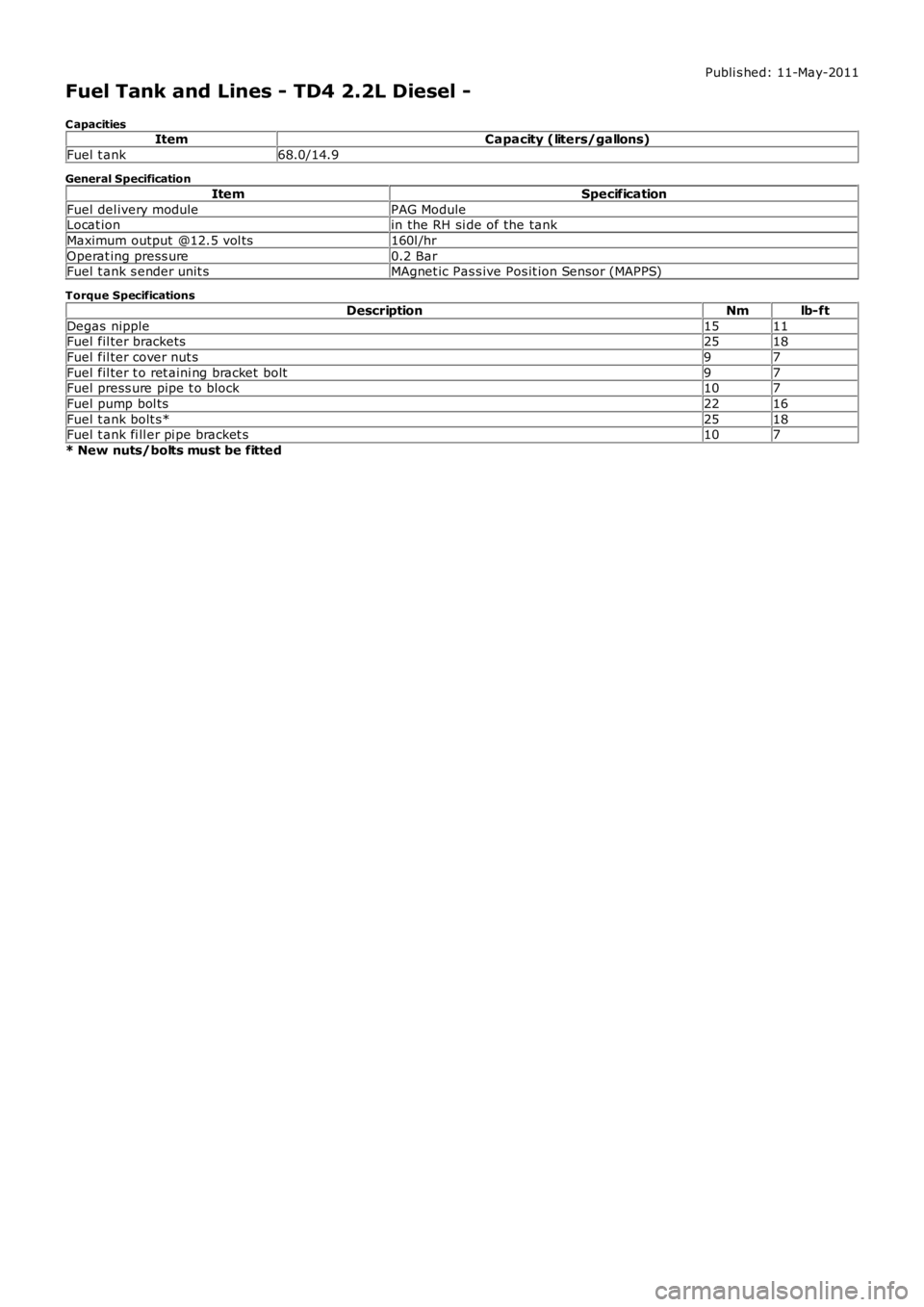
Fuel Tank and Lines - TD4 2.2L Diesel -
C apacitiesItemCapacity (liters/gallons)
Fuel t ank68.0/14.9
General Specification
ItemSpecification
Fuel del ivery modulePAG ModuleLocat ionin the RH si de of the tank
Maximum output @12.5 vol ts160l /hr
Operat ing press ure0.2 BarFuel t ank s ender unit sMAgnet ic Pas s ive Pos it ion Sensor (MAPPS)
Torque Specifications
DescriptionNmlb-ft
Degas nipple1511Fuel fil ter brackets2518
Fuel fil ter cover nut s97
Fuel fil ter t o ret aini ng bracket bolt97Fuel press ure pipe t o block107
Fuel pump bol ts2216
Fuel t ank bolt s*2518Fuel t ank fi ll er pi pe bracket s107
* New nuts/bolts must be fitted