2006 LAND ROVER FRELANDER 2 sensor
[x] Cancel search: sensorPage 1593 of 3229
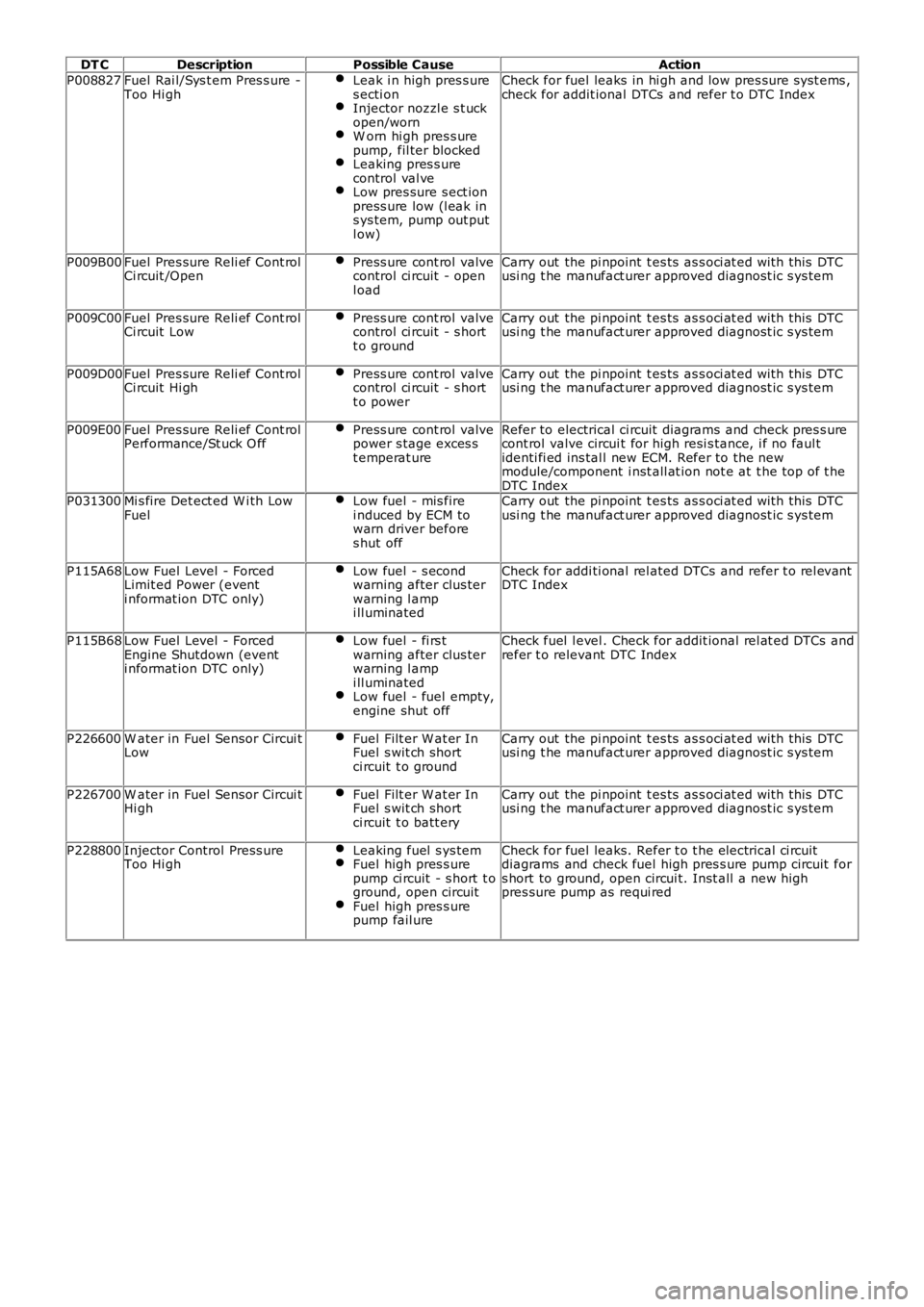
DT C
Description Possible Cause Action
P008827 Fuel Rai l/Sys t em Pres s ure -
Too Hi gh Leak i n high pres s ure
s ecti on Injector nozzl e s t uck
open/worn W orn hi gh pres s ure
pump, fil ter blocked Leaking pres s ure
control val ve Low pres sure s ect ion
press ure low (l eak in
s ys tem, pump out put
l ow) Check for fuel leaks in hi gh and low pres sure s yst ems ,
check for addit ional DTCs and refer t o DTC Index
P009B00 Fuel Pres sure Reli ef Cont rol
Ci rcuit /Open Press ure cont rol valve
control ci rcuit - open
l oad Carry out the pi npoint t es ts as s oci at ed wi th this DTC
usi ng t he manufact urer approved diagnost ic s ys tem
P009C00 Fuel Pres sure Reli ef Cont rol
Ci rcuit Low Press ure cont rol valve
control ci rcuit - s hort
t o ground Carry out the pi npoint t es ts as s oci at ed wi th this DTC
usi ng t he manufact urer approved diagnost ic s ys tem
P009D00 Fuel Pres sure Reli ef Cont rol
Ci rcuit Hi gh Press ure cont rol valve
control ci rcuit - s hort
t o power Carry out the pi npoint t es ts as s oci at ed wi th this DTC
usi ng t he manufact urer approved diagnost ic s ys tem
P009E00 Fuel Pres sure Reli ef Cont rol
Performance/St uck O ff Press ure cont rol valve
power s tage exces s
t emperat ure Refer to electrical ci rcuit diagrams and check pres s ure
cont rol valve circui t for high resi s tance, i f no faul t
identi fi ed ins tal l new ECM. Refer to the new
module/component i nst all at ion not e at t he top of t he
DTC Index
P031300 Mi s fire Det ect ed W i th Low
Fuel Low fuel - mis fire
i nduced by ECM to
warn driver before
s hut off Carry out the pi npoint t es ts as s oci at ed wi th this DTC
usi ng t he manufact urer approved diagnost ic s ys tem
P115A68 Low Fuel Level - Forced
Limit ed Power (event
i nformat ion DTC only) Low fuel - s econd
warning after clus ter
warning l amp
i ll uminated Check for addi ti onal rel ated DTCs and refer t o rel evant
DTC Index
P115B68 Low Fuel Level - Forced
Engine Shutdown (event
i nformat ion DTC only) Low fuel - fi rs t
warning after clus ter
warning l amp
i ll uminated Low fuel - fuel empty,
engine shut off Check fuel l evel . Check for addit ional rel at ed DTCs and
refer t o relevant DTC Index
P226600 W ater in Fuel Sensor Circui t
Low Fuel Filt er W at er In
Fuel s wit ch short
ci rcuit t o ground Carry out the pi npoint t es ts as s oci at ed wi th this DTC
usi ng t he manufact urer approved diagnost ic s ys tem
P226700 W ater in Fuel Sensor Circui t
Hi gh Fuel Filt er W at er In
Fuel s wit ch short
ci rcuit t o batt ery Carry out the pi npoint t es ts as s oci at ed wi th this DTC
usi ng t he manufact urer approved diagnost ic s ys tem
P228800 Injector Control Press ure
Too Hi gh Leaking fuel s ys tem Fuel high pres s ure
pump ci rcuit - s hort t o
ground, open circuit Fuel high pres s ure
pump fail ure Check for fuel leaks. Refer t o t he electrical ci rcuit
diagrams and check fuel high pres s ure pump circuit for
s hort to ground, open circui t. Inst all a new high
pres sure pump as requi red
Page 1617 of 3229
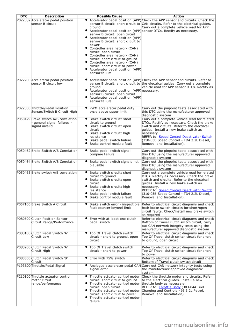
DT CDescriptionPossible CauseAction
P022082Accel erat or pedal pos i ti ons ens or B ci rcuitAccelerator pedal pos it ion (APP)s ens or B circui t: short ci rcuit t ogroundAccelerator pedal pos it ion (APP)s ens or B circui t: open circui tAccelerator pedal pos it ion (APP)s ens or B circui t: short ci rcuit t opowerControl ler area net work (CAN)circuit : open circuitControl ler area net work (CAN)circuit : s hort circui t to groundControl ler area net work (CAN)circuit : s hort circui t to powerAccelerator pedal pos it ion (APP)s ens or fai lure
Check t he APP s ensor and circui ts . Check theCAN circui ts . Refer t o t he electrical gui des .Carry out a complete vehi cl e read for APPs ens or DTCs. Recti fy as neces sary.
P022200Accel erat or pedal pos i ti ons ens or B ci rcuit l owAccelerator pedal pos it ion (APP)s ens or B circui t: short ci rcuit t ogroundAccelerator pedal pos it ion (APP)s ens or B circui t: open circui tAccelerator pedal pos it ion (APP)s ens or fai lure
Check t he APP s ensor and circui ts . Refer t othe el ect ri cal guides . Carry out a compl etevehi cl e read for APP s ens or DTCs . Rect ify asneces s ary.
P022300Throt t le/Pedal Pos it ionSens or/Swi tch B Circui t HighPW M accelerat or pedal dutycycle above upper li mitCarry out the pi npoi nt t es ts as s oci ated wi ththi s DTC us ing t he manufacturer approveddiagnos t ic s ys temP050429Brake swit ch A/B correlat ion- general s ignal fail ures -s i gnal invali d
Brake s wi tch circui t: s hortcircuit to groundBrake s wi tch circui t: opencircuitBrake s wi tch circui t: hi ghres is t anceBrake pedal swi tch fail ureBrake control modul e faul t
Carry out a complete vehi cl e read for rel at edDTCs. Recti fy as neces sary. Check the brakes wit ch and ci rcuit s . Refer to the el ect ri calguides. Ins tall a new brake s wit ch asneces s ary.REFER to: Speed Cont rol Deacti vat or Swi tch(310-03B Speed Control - TD4 2.2L Di esel ,Removal and Inst all at ion).
P050462Brake Swit ch A/B Correl at ionBrake pedal swi tch s i gnalcompare failureCarry out the pi npoi nt t es ts as s oci ated wi ththi s DTC us ing t he manufacturer approveddiagnos t ic s ys temP050464Brake Swit ch A/B Correl at ionBrake pedal swi tch s i gnals notplaus ibleCarry out the pi npoi nt t es ts as s oci ated wi ththi s DTC us ing t he manufacturer approveddiagnos t ic s ys tem
P050465Brake swit ch A/B correlat ionBrake s wi tch circui t: s hortcircuit to groundBrake s wi tch circui t: opencircuitBrake s wi tch circui t: hi ghres is t anceBrake pedal swi tch fail ureBrake control modul e faul t
Carry out a complete vehi cl e read for rel at edDTCs. Recti fy as neces sary. Check the brakes wit ch and ci rcuit s . Refer to the el ect ri calguides. Ins tall a new brake s wit ch asneces s ary.REFER to: Speed Cont rol Deacti vat or Swi tch(310-03B Speed Control - TD4 2.2L Di esel ,Removal and Inst all at ion).
P057100Brake Swit ch A Circui tBrake s wi tch error - ins pect iblefaul t counter beyond limitRefer t o electrical ci rcuit diagrams and checkboth brake swit ch ci rcuit s for s hort /opencircuit fault s. Check/ins t al l new brake s wit chas required
P080600Cl utch Pos it ion SensorCi rcuit Range/PerformanceError wit h at leas t one clutchpedal s wit chRefer t o electrical ci rcuit diagrams and checkBott om of Travel clutch s wi tch circui t, carryout CAN network int egrit y t est s us ing t hemanufacturer approved diagnost ic sys tem
P083100Cl utch Pedal Swi tch 'A'Ci rcuit LowTop Of Travel cl utch s wit chcircuit - short to ground, opencircuit
Refer t o electrical ci rcuit diagrams and checkTop Of Travel cl utch s wit ch circuit for s hortto ground, open circui t
P083200Cl utch Pedal Swi tch 'A'Ci rcuit Hi ghTop Of Travel cl utch s wit chcircuit - short to powerRefer t o electrical ci rcuit diagrams and checkTop Of Travel cl utch s wit ch circuit for s hortto power
P083300Cl utch Pedal Swi tch 'B'Ci rcuitError wit h 75% swi tchRefer t o electrical ci rcuit diagrams and checkBott om of Travel clutch s wi tch circui t
P193B00Throt t le/Pedal Si gnalAnalogue accelerat or pedal CANs ignal errorCarry out CAN network int egrit y t est s us ingthe manufact urer approved diagnos t ics ys t emP210100Throt t le actuat or controlmot or circuitrange/performance
Throt tl e act uator cont rol mot orcircuit : s hort circui t to groundThrot tl e act uator cont rol mot orcircuit : open circuitThrot tl e act uator cont rol mot orcircuit : s hort circui t to powerThrot tl e act uator cont rol mot orfai lure
Check t he t hrott le motor and circui ts . Referto the el ect ri cal guides . Ins tal l a newthrott le body as necess ary.REFER to: Throt tl e Body (303-04A FuelCharging and Cont rols - I6 3.2L Petrol,Removal and Inst all at ion).
Page 1628 of 3229
Publi s hed: 11-May-2011
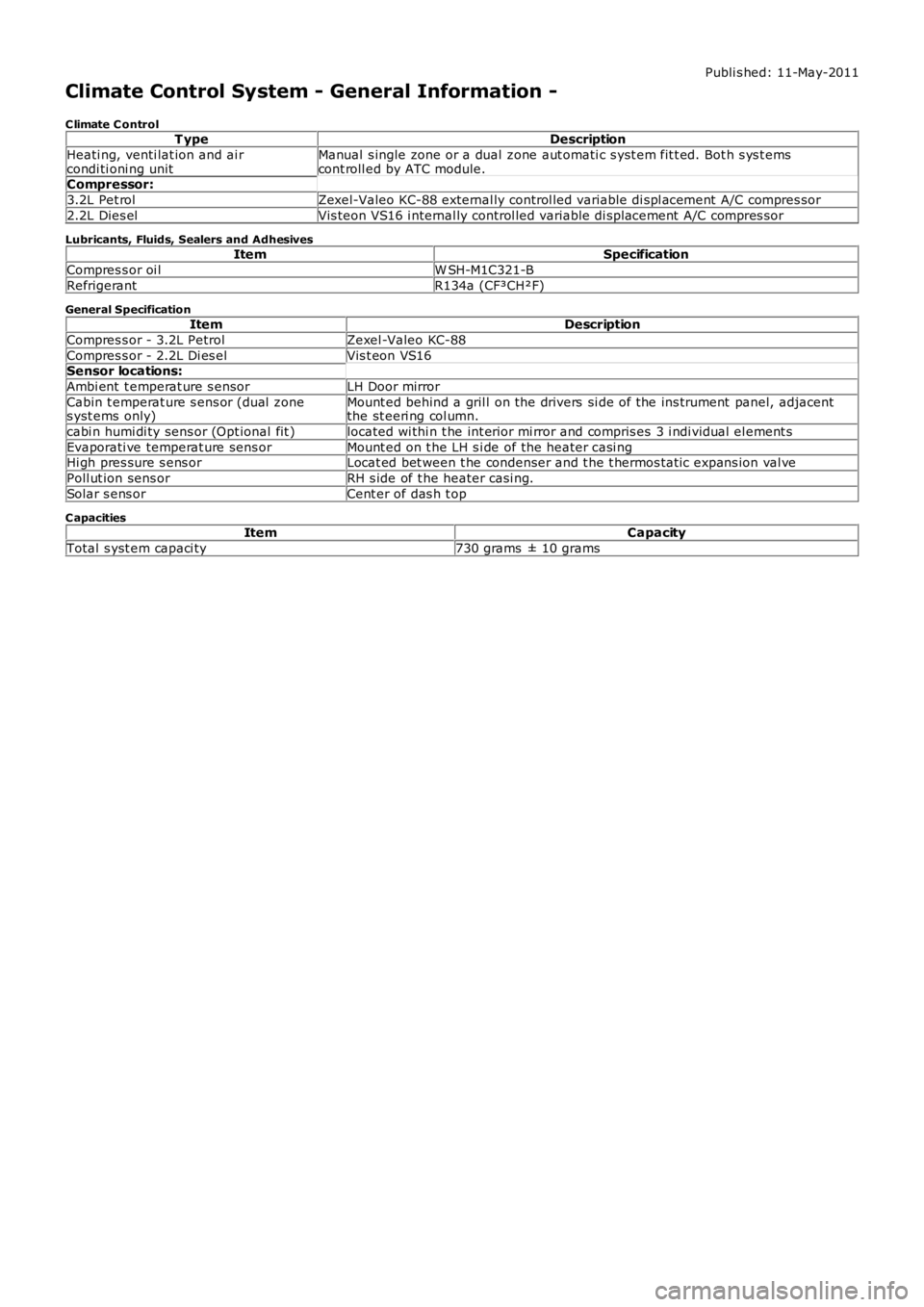
Climate Control System - General Information -
C limate C ontrolT ypeDescription
Heati ng, venti lat ion and ai rcondi ti oni ng unitManual s ingle zone or a dual zone aut omati c s yst em fit t ed. Bot h s ys t emscont roll ed by ATC module.Compressor:
3.2L Pet rolZexel-Valeo KC-88 external ly control led variable di spl acement A/C compres sor
2.2L Dies elVis teon VS16 i nternal ly control led variable di spl acement A/C compres sor
Lubricants, Fluids, Sealers and AdhesivesItemSpecification
Compres s or oi lW SH-M1C321-B
RefrigerantR134a (CF³CH²F)
General SpecificationItemDescription
Compres s or - 3.2L PetrolZexel -Valeo KC-88
Compres s or - 2.2L Di es elVis t eon VS16Sensor locations:
Ambi ent t emperat ure s ensorLH Door mirror
Cabin t emperat ure s ens or (dual zones yst ems only)Mount ed behind a gril l on the drivers si de of the ins trument panel, adjacentthe st eeri ng col umn.
cabi n humi di ty sens or (Opt ional fit )located wi thi n t he int erior mi rror and compris es 3 i ndi vidual el ement s
Evaporati ve temperat ure sens orMount ed on t he LH s i de of the heater casi ngHi gh pres sure s ens orLocat ed bet ween t he condenser and t he t hermos tat ic expans ion val ve
Poll ut ion sens orRH s ide of t he heater casi ng.
Solar s ens orCent er of das h t op
C apacitiesItemCapacity
Total s yst em capaci ty730 grams ± 10 grams
Page 1640 of 3229
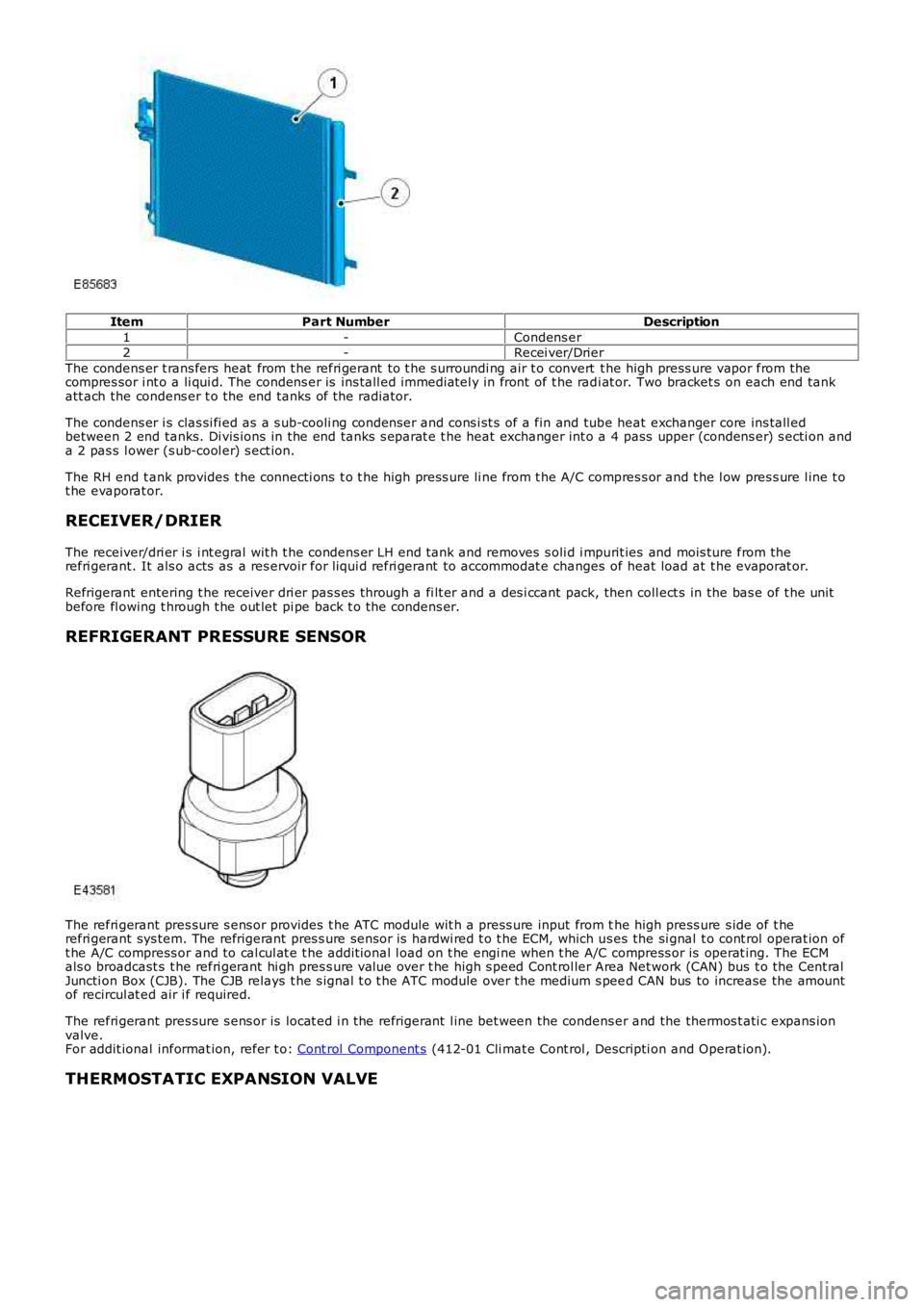
ItemPart NumberDescription
1-Condens er2-Recei ver/Drier
The condens er t rans fers heat from t he refri gerant to t he s urroundi ng air t o convert t he high press ure vapor from thecompres sor i nt o a li qui d. The condens er is ins tall ed immediatel y in front of t he radi at or. Two bracket s on each end tankatt ach the condens er t o the end tanks of the radiator.
The condens er i s clas si fi ed as a s ub-cooli ng condenser and cons i st s of a fin and tube heat exchanger core ins tall edbetween 2 end tanks. Di vis ions in the end tanks s eparat e t he heat exchanger int o a 4 pass upper (condens er) s ecti on anda 2 pas s l ower (s ub-cool er) s ect ion.
The RH end t ank provides t he connecti ons t o t he high press ure li ne from t he A/C compres s or and t he l ow pres s ure l ine t ot he evaporat or.
RECEIVER/DRIER
The receiver/dri er i s i nt egral wit h t he condens er LH end tank and removes s oli d i mpurit ies and mois ture from therefri gerant. It als o acts as a res ervoir for liqui d refri gerant to accommodat e changes of heat load at t he evaporat or.
Refrigerant entering t he receiver dri er pas s es through a fi lt er and a des i ccant pack, then coll ect s in the bas e of t he unitbefore fl owing t hrough t he out let pi pe back t o t he condens er.
REFRIGERANT PRESSURE SENSOR
The refri gerant pres sure s ens or provides t he ATC module wit h a press ure input from the high press ure s ide of t herefri gerant sys tem. The refrigerant pres s ure sens or is hardwi red t o t he ECM, which us es the si gnal t o cont rol operat ion oft he A/C compress or and to cal cul at e t he addit ional l oad on t he engi ne when t he A/C compress or is operat ing. The ECMals o broadcast s t he refri gerant hi gh pres s ure value over t he high s peed Cont rol ler Area Net work (CAN) bus t o the Cent ralJuncti on Box (CJB). The CJB relays t he s ignal t o t he ATC module over t he medium s peed CAN bus to increase the amountof recircul at ed air i f required.
The refri gerant pres sure s ens or is locat ed i n the refrigerant l ine bet ween the condens er and the thermos t ati c expans ionvalve.For addit ional informat ion, refer t o: Cont rol Component s (412-01 Cli mat e Cont rol , Descripti on and Operat ion).
THERMOSTATIC EXPANSION VALVE
Page 1644 of 3229
Publishe d: 11-May-2011
Climate Control - Control ComponentsDescripti on a nd O pe ration
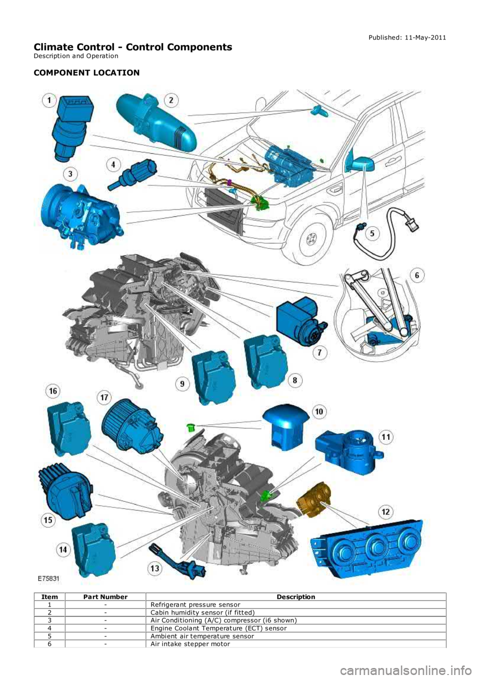
COMPONENT LOCATION
ItemPart NumberDe scription1-Refrigera nt press ure sens or2-Cabin humidi ty s ensor (if fitt ed)3-Air Condi tioning (A/C) compressor (i6 shown)4-Engine Coola nt Temperat ure (ECT) s ensor5-Ambi ent air t emperat ure sensor6-Air intake ste ppe r motor
Page 1645 of 3229
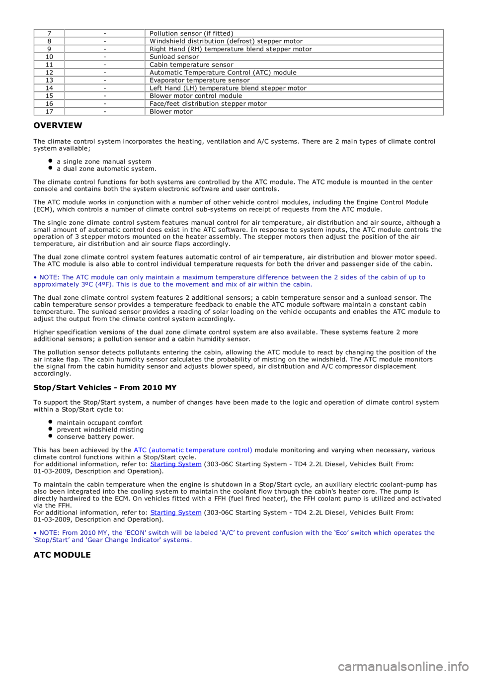
7-P ollution sensor (if fi tted)8-W indshie ld distri buti on (defrost) ste pper motor9-Right Hand (RH) tempera ture ble nd s tepper mot or10-Sunload s ens or11-Cabin temperature se nsor12-Automati c Te mpe rature Cont rol (ATC) modul e13-Evaporator te mpe rature s ens or14-Left Hand (LH) te mpe rature blend st eppe r motor15-Blowe r motor control module16-Face/feet dis tribution ste ppe r motor17-Blowe r motor
OVERVIEW
The clima te cont rol s yste m i ncorpora tes the hea ting, ve ntila tion and A/C systems. There are 2 mai n types of clima te controls yste m a vail able ;
a single z one ma nual sys tema dua l zone a utomati c system.
The clima te cont rol f unct ions for bot h systems a re controlle d by the ATC modul e. The ATC module is mounted in the ce nte rcons ole a nd cont ains bot h the syste m e lectronic sof twa re a nd user cont rols .
The ATC module works in conjunction wi th a number of othe r ve hicle control module s, i ncluding the Engine Control Module(ECM), which control s a number of cl ima te control sub-s yste ms on recei pt of reques ts f rom the ATC module .
The s ingle zone climate cont rol s yst em f eat ures ma nual control for air t empera ture , air dist ribution and air source, although as mal l amount of aut oma tic control does exis t in the ATC softwa re. In re sponse to s yste m i nput s, t he ATC module cont rols theopera tion of 3 st epper motors mounted on t he heat er as sembly. The st eppe r motors then a djust the positi on of the ai rt emperat ure, air dist ribution and air source flaps accordingly.
The dual zone cl imat e control system fe atures a utomati c control of air t empera ture , air dis tribution and blower motor s pee d.The ATC module is a lso able to cont rol i ndividua l te mpe rature re que sts for both the dri ver a nd pass enger s ide of the cabin.
• NO TE: The ATC module can only maint ain a maximum tempera ture dif fere nce bet wee n the 2 side s of the cabin of up toa pproximate ly 3ºC (4ºF). This is due to the moveme nt a nd mix of a ir wi thin the cabin.
The dual zone cl imat e control system fe atures 2 additional sens ors; a cabin temperature se nsor and a sunload sensor. Thecabin temperature se nsor provides a temperature fe edback to e nabl e the ATC module s oftware mai ntai n a cons tant ca bint emperat ure. The sunloa d se nsor provide s a rea ding of s ola r loa ding on the vehicle occupants a nd enables the ATC module toa djus t the output from t he clima te control s yste m a ccordingly.
Higher specif icat ion vers ions of t he dual zone cl imat e control system are al so a vailable . These syst ems fea ture 2 morea ddit iona l se nsors; a polluti on s ensor and a cabin humidity sensor.
The pollution sensor det ects pol luta nts ente ring the cabin, allowing the ATC modul e to rea ct by cha ngi ng t he posit ion of thea ir intake fla p. The cabin humidi ty s ensor ca lcul ates the probability of misti ng on the winds hiel d. The ATC module monitorst he s igna l from t he cabin humidi ty s ensor and a djus ts blowe r speed, air dis tribution and A/C compress or di spla cementa ccordingly.
Stop/Start Vehicles - From 2010 MY
To support the Stop/Start system, a number of changes have be en made to the logic and opera tion of climate cont rol s yst emwithi n a Stop/Sta rt cycle to:
maint ain occupant comfortpreve nt winds hie ld mistingconse rve batt ery power.
This has bee n achieved by the ATC (automa tic t emperat ure control) module monitoring and varying when nece ssary, va riousclima te control funct ions wit hin a St op/Start cycle.For a ddit iona l inf ormation, re fer to: Starting Sys tem (303-06C Start ing Syst em - TD4 2.2L Diese l, Vehicles Buil t From:01-03-2009, Des cript ion and Ope rati on).
To maint ain the cabi n te mpe rature when the engine is s hut down in a St op/Start cycle, an a uxil iary electric coolant-pump hasa lso bee n int egra ted into the cooling system to mai ntai n the coolant flow t hrough t he cabi n’s heat er core. The pump isdirectly hardwire d to the ECM. O n ve hicl es fi tted wit h a FFH (fue l fired heat er), the FFH coolant pump i s uti lize d and activa tedvia t he FFH.For a ddit iona l inf ormation, re fer to: Starting Sys tem (303-06C Start ing Syst em - TD4 2.2L Diese l, Vehicles Buil t From:01-03-2009, Des cript ion and Ope rati on).
• NO TE: From 2010 MY , the 'ECO N' s witch will be la bele d ‘A/C’ t o prevent confusion wit h the ‘Eco’ s witch which ope rate s the‘Stop/Sta rt’ a nd 'Gea r Change Indica tor' syst ems .
ATC MODULE
Page 1646 of 3229
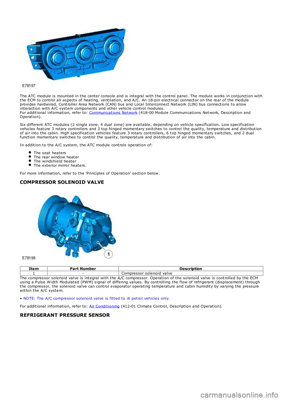
The ATC module is mounted in t he cente r console a nd is int egra l wi th t he control panel . The modul e works in conjunct ion witht he ECM to control a ll as pect s of hea ting, ve ntil ation, and A/C. An 18-pin el ectrical connect or on the re ar of the moduleprovi des hardwired, Cont rolle r Area Network (CAN) bus a nd Loca l Interconne ct Network (LIN) bus conne ctions t o al lowi nteraction with A/C syst em components and other vehicle control modules.For a ddit iona l inf ormation, re fer to: Communicat ions Ne twork (418-00 Module Communi cati ons Net work, De scri ption andO peration).
Six different ATC module s (2 single zone , 4 dual zone) a re a vail able , de pending on vehicle spe cifica tion. Low s peci fica tionvehicles feat ure 3 rotary controll ers and 3 top hi nge d mome ntary switches t o control the qualit y, te mpe rature a nd dist ribut ionof ai r int o the ca bin. High specif icati on vehicles feat ure 3 rotary control lers, 6 top hinge d mome nta ry s witches, and 2 dualf unct ion moment ary swit che s to control the qua lity, tempera ture and di stribution of air into the cabin.
In additi on t o the A/C system, t he ATC module cont rols ope ration of:
The s eat hea tersThe rear window heat erThe winds hie ld he ate rThe e xterior mirror he ate rs.
For more informa tion, re fer t o the 'P rinci ples of O pe ration' s ection below.
COMPRESSOR SOLENOID VALVE
Ite mPart NumberDescription1-Compres sor sole noi d va lveThe compres sor sole noid val ve is int egra l wi th t he A/C compres sor. Ope rati on of the solenoid valve is cont rolle d by the ECMusing a P ulse W i dth Modulat ed (PW M) s igna l of diffe ring va lues . By controll ing the flow of refri gera nt (displace ment) t hrought he compress or, the sole noid va lve can cont rol e vaporat or opera ting temperature and cabin humidit y by va rying the pre ssurewithi n the A/C syste m.
• NO TE: The A/C compre ssor sol enoid va lve is fi tted to i6 petrol vehicle s only.
For a ddit iona l inf ormation, re fer to: Air Conditioning (412-01 Cli mat e Control, Description a nd O peration).
REFRIGERANT PRESSURE SENSOR
Page 1647 of 3229
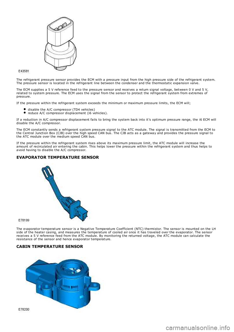
The refrigera nt press ure sensor provides the ECM wi th a pre ssure input from the high press ure side of t he refri gera nt s yste m.The pres sure sensor is locat ed in the ref rige rant line be twee n the conde nse r and the thermosta tic expa nsion valve .
The ECM supplie s a 5 V reference fe ed t o the pressure s ens or a nd recei ves a re turn signal volta ge, bet wee n 0 V and 5 V,relat ed t o system pressure. The ECM use s the s igna l from t he s ensor to protect the ref rigerant sys tem from extremes ofpress ure .
If the pre ssure withi n the re frige rant sys tem exceeds the minimum or maximum pre ssure li mits , the ECM will;
disable the A/C compress or (TD4 vehicles )re duce A/C compress or di spla cement (i6 vehi cles ).
If a reduction in A/C compre ssor displace me nt fa ils to bring the sys tem back into it's optimum pres sure range, the i6 ECM willdisable t he A/C compres sor.
The ECM constantly sends a refrigera nt s yst em pres sure signal to the ATC module. The signal i s tra nsmitte d from the ECM tot he Cent ral Junct ion Box (CJB) over the high spe ed CAN bus . The CJB acts a s a gate way and provides t he press ure signal t ot he ATC module over the me dium speed CAN bus.
If the pre ssure withi n the re frige rant sys tem rise s a bove its ma ximum press ure limit, the ATC module will incre ase thea mount of re circulate d a ir enteri ng t he cabin. This helps lower t he press ure wit hin t he refrigera nt s yste m a nd t hus helps toa void ha ving to disa ble t he A/C compres sor.
EVAPORATOR TEMPERATURE SENSOR
The e vaporat or t emperat ure sensor is a Negative Te mpe rature Coef ficie nt (NTC) the rmistor. The se nsor is mounted on the LHs ide of the heate r ca sing, and meas ures the temperature of cooled air once it has t rave led ove r the evaporator. The se nsorrecei ves a 5 V re fere nce feed from the ATC module. By monitori ng t he returned volt age , the ATC module ca n ca lcul ate theresis tance of the sensor and hence e vaporat or t emperat ure.
CABIN TEMPERATURE SENSOR