2006 LAND ROVER FRELANDER 2 sensor
[x] Cancel search: sensorPage 2480 of 3229
s eat , or an unres trained but very l ightwei ght adult , in bot h t hes e cas es the ai r bag would be di sabl ed. The occupantclas si fi cat ion s ens ing s yst em forms part of a s t rat egy t o control pas s enger air bag deployment depending on theoccupancy s cenario.
The occupant cl as s ificati on s ys t em has four pos s ible st ates :
Seat Empty: t he pass enger ai r bag, pas senger-s ide air bag and pas s enger s afety bel t buckle and pretens ioneroperati on is di s abl ed; t he pas senger air bag deact ivati on indicator i s not il luminated.Occupied Inhibit: when the seat is occupied by a smal l pers on, t he pass enger ai r bag, pas senger-s ide air bag andpass enger s afet y belt buckl e and pret ensi oner operat ion i s dis abled; the pas s enger air bag deact ivat ion i ndi cat or isil lumi nat ed.Occupied Allow: when t he s eat i s occupied by a large pers on; t he pas senger ai r bag and pass enger-s ide air bagoperati on is enabled, t he pas s enger ai r bag deacti vat ion i ndicat or is not i ll uminated. Pass enger s afet y belt andpret ens i oner operati on s tat us depends on t he s afet y bel t buckle s tat us :- acti ve for buckled,- inacti ve for unbuckled.Error: if a sys tem faul t is det ect ed; t he pas senger ai r bag is enabled t o deploy at 'st age-1' onl y, refer t o Air BagDual St age Inflat ors below. Pas senger-s ide air bag operat ion i s als o enabled; t he pas s enger air bag deacti vat ionindicat or i s not il lumi nat ed. Pas s enger s afety bel t and pret ens ioner operati on s tat us depends on t he s afety bel tbuckle s tat us :- acti ve for buckled,- inacti ve for unbuckled.
Occupancy Sensor Mod ule
The occupancy s ens or modul e is ins tall ed on t he undersi de of the front pas s enger s eat . The module s upplies a power feedt o the occupancy s ens or and monit ors the return vol tage t o det ermi ne if t he s eat i s occupied or not . The res ult ist ransmit ted t o t he RCM on the hi gh-s peed CAN. The occupancy s ens or module al so monitors for s hort and open circui ts int he occupancy s ensor. If i t det ect s a fault , the occupancy s ens or module t rans mi ts a fault mess age t o t he RCM.
Safety Belt Tension Sensor
The s afety bel t tens ion s ens or i s a s t rai n-gauge type, encapsul at ed wi thi n the pas s enger s afet y belt anchor. The sens orconvert s t he force appl ied t o t he s afety bel t int o an elect rical s ignal. In the event t hat a chi ld-s eat is ins tall ed onto thefront pas s enger s eat, t he force appl ied t o t he pass enger s afet y belt i s reflected by the out put s i gnal from the s ensor,which provi des dat a t o s uppl ement that received from the occupancy s ens or. The occupancy sens or modul e proces ses t heinput data and makes i t avai lable to the rest rai nts control modul e, whi ch then makes t he neces s ary adjus t ments i nres pect of pas senger air bag deployment .
2. Occupant Detection Sensing System
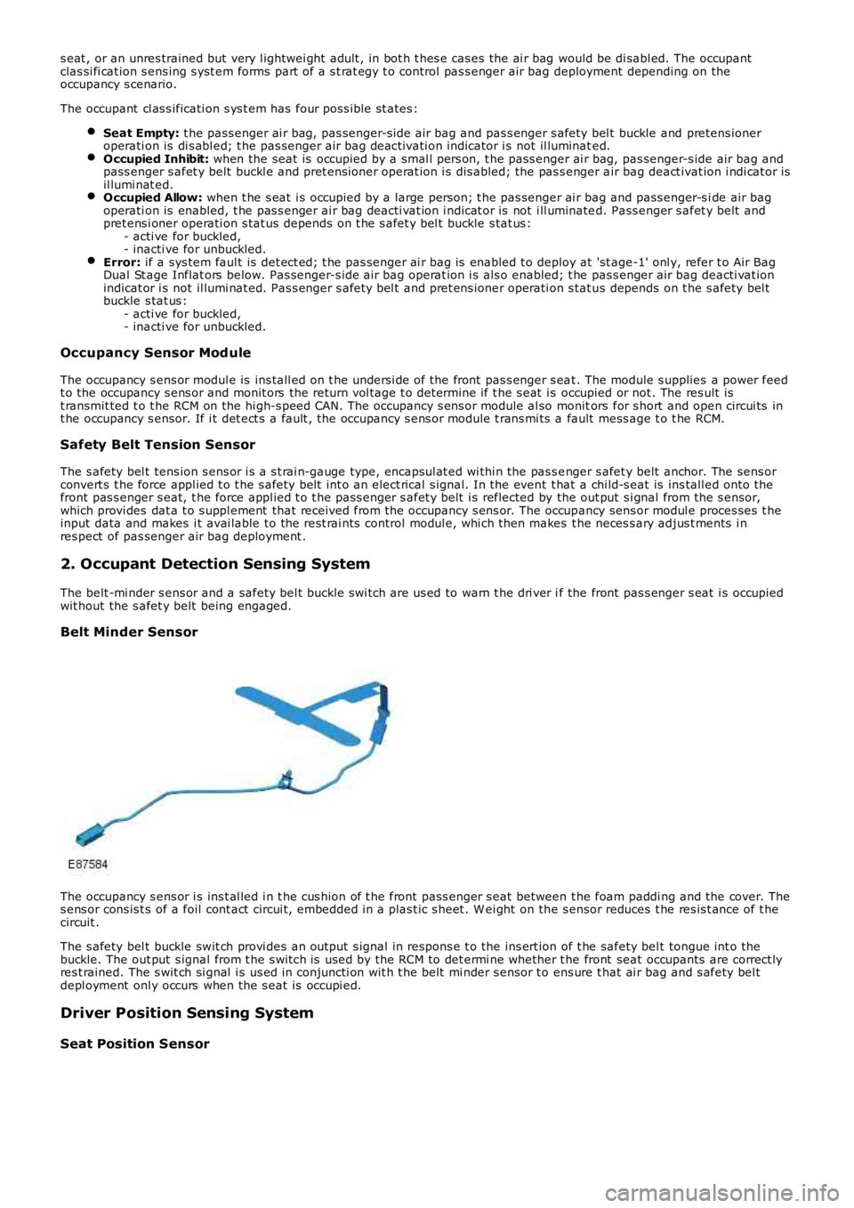
The belt -mi nder s ens or and a safety bel t buckle s wi tch are us ed to warn t he dri ver if the front pas s enger s eat i s occupiedwit hout the s afet y belt being engaged.
Belt Minder Sensor
The occupancy s ens or i s ins t al led i n t he cus hion of t he front pass enger s eat between t he foam paddi ng and the cover. Thes ens or cons is t s of a foil cont act circui t, embedded in a plas t ic s heet . W ei ght on the s ensor reduces t he res is t ance of t hecircuit .
The s afety bel t buckle swit ch provi des an output s ignal in respons e t o the ins ert ion of t he safety bel t tongue int o t hebuckle. The out put s ignal from t he s wit ch is used by the RCM to det ermi ne whether t he front seat occupants are correct lyres t rained. The s wit ch si gnal i s us ed in conjuncti on wit h t he belt mi nder s ensor t o ens ure t hat ai r bag and s afety bel tdepl oyment onl y occurs when the s eat is occupi ed.
Driver Position Sensing System
Seat Position Sensor
Page 2486 of 3229
Publi s hed: 11-May-2011
Supplemental Restraint System - Air Bag Supplemental Restraint System
(SRS)
Diagnosi s and Tes ti ng
Principles of Operation
For a detail ed descripti on of the ai r bag s upplement al res traints sys tem, refer t o the rel evant Des cript ion and Operat ions ect ion i n t he works hop manual .REFER to: Ai r Bag and Safety Bel t Pretens ioner Suppl ement al Res t raint Sys tem (SRS) (501-20B Suppl ement al Res t rai ntSyst em, Des cript ion and Operat ion).
Inspection and Verification
W ARNING: TO AVOID ACCIDENTAL DEPLOY MENT AND POSSIBLE PERSONAL INJURY , THE BACKUP POWER SUPPLYMUST BE DEPLETED BEFORE REPAIRING OR REPLACING ANY AIR BAG SUPPLEMENTAL RESTRAINT SYSTEM (SRS)COMPONENTS. TO DEPLETE THE BACKUP POW ER SUPPLY ENERGY , DISCONNECT THE BATTERY GRO UND CABLE AND W AITTW O MINUTES. FAILURE TO FOLLOW THIS INSTRUCTION MAY RESULT IN PERSONAL INJURY .
CAUTION: Di agnos is by s ubs ti tut ion from a donor vehicle is NO T acceptabl e. Subs ti tut ion of cont rol modules doesnot guarant ee confirmat ion of a faul t, and may als o caus e addit ional fault s i n t he vehi cl e being t est ed and/or t he donorvehi cl e.
• NOTE: Given t he l egal impl icati ons of a res t raint s s ys t em fail ure, harness repairs to Air Bag module ci rcuit s are notacceptable. W here t he t ext refers to "REPAIR the circui t", t hi s wi ll normal ly mean the repl acement of a harnes s .
1. Verify t he cus t omer concern.1.
2. Vis ually ins pect for obvious s igns of damage.2.
Visual Inspection
ElectricalBatt ery condit ion, s tat e of chargeMake s ure al l elect rical connect or(s) are engaged correct ly on the ai r bag ci rcuit sW iri ng harnes sAir bag modul e(s )Make s ure the rest rai nts control modul e (RCM) is correct ly ins tall edFuse(s )Sensor(s )Pret ensi oner(s )W arning l amp bulb(s)
3. If an obvious cause for an obs erved or report ed concern is found, correct t he caus e (if pos s ible) beforeproceeding t o t he next s t ep3.
4. If t he caus e is not vis ually evi dent , check Rest rai nts Cont rol Modul e (RCM) and Occupancy Cl ass i ficat ion Syst em(OCS) module for Diagnos t ic Troubl e Codes (DTCs ) and refer t o t he DTC Index.4.
Given t he complexit y of the s ys tem and the pot enti al for damage/injury, t he preferred met hod of di agnos is i s via theManufacturer approved diagnost ic sys tem.
If the Manufacturer approved di agnos ti c s ys t em i s not avai lable, use a s can tool to ext ract DTCs and refer to the DTCIndex.
DTC Index
• NOTE: If the control modul e is sus pect and t he vehicle remains under manufact urer warranty, refer to the W arrant y Poli cyand Procedures manual (s ect ion B1.2), or determine i f any prior approval programme is i n operat ion, prior t o t heins t al lat ion of a new modul e.
• NOTE: Generic scan t ool s may not read the codes li st ed, or may read only fi ve digit codes . Mat ch the five di git s from t hes can tool to the firs t fi ve di git s of the seven digi t code l is ted to ident ify t he faul t (t he las t t wo digi ts gi ve addi ti onalinformat ion read by the manufact urer approved diagnos t ic s ys tem).
• NOTE: W hen performing el ect ri cal volt age or resi s tance tes t s, al ways us e a digit al mult imet er (DMM) accurate to threedeci mal places , and wi th an up-to-date cali brat ion cert ificate. W hen t es ti ng res is t ance, always take t he res i st ance of t heDMM leads int o account.
• NOTE: Check and recti fy bas ic faul ts before beginni ng diagnos t ic rout ines i nvol vi ng pinpoint t es t s.
• NOTE: Ins pect connect ors for s igns of water ingres s , and pins for damage and/or corros ion.
• NOTE: If DTCs are recorded and, aft er performi ng the pi npoi nt tes ts , a fault is not present , an int ermi tt ent concern maybe t he caus e. Always check for loose connect ions and corroded terminals .
For a compl ete lis t of all Di agnos ti c Trouble Codes (DTCs) t hat could be logged on this vehicle, pleas e refer to Sect ion100-00
REFER to: Di agnos ti c Trouble Code (DTC) Index - DTC: Res trai nts Cont rol Module (RCM) (100-00 General Informati on,Des cript ion and Operat ion).
Page 2499 of 3229
Publi s hed: 11-May-2011
Supplemental Restraint System - Occupant Classification Sensor
Removal and Inst all ati on
Removal
• NOTE: The occupant cl ass ificati on s ens or is part of the pas s enger s eat cus hion. The sens or is only fi tt ed t o NAS models .
Di sconnect t he bat t ery ground cable.
Refer t o: Specificati ons (414-00 Bat tery and Charging Sys tem -General Informat ion, Specificati ons).
1.
Remove t he front seat cushi on cover.
Refer t o: Front Seat Cus hion Cover (501-10 Seati ng, Removal andInst all at ion).
2.
Installation
Inst all t he front seat cushi on cover.
Refer t o: Front Seat Cus hion Cover (501-10 Seati ng, Removal andInst all at ion).
1.
Connect t he batt ery ground cable.
Refer t o: Specificati ons (414-00 Bat tery and Charging Sys tem -General Informat ion, Specificati ons).
2.
Us ing IDS, configure a new occupant cl ass i fi cat ion s ensor.3.
Page 2500 of 3229
Publi s hed: 11-May-2011
Supplemental Restraint System - B-Pillar Side Impact Sensor
Removal and Inst all ati on
Removal
• NOTE: Removal s t eps in t his procedure may cont ain i nst all ati on det ail s.
Di sconnect t he bat t ery ground cable.
Refer t o: Specificati ons (414-00 Bat tery and Charging Sys tem -
General Informat ion, Specificati ons).
1.
Make t he SRS s ys t em s afe.
Refer t o: Standard W orks hop Pract ices (100-00 General Informat ion,
Des cript ion and Operat ion).
2.
Remove t he front scuff pl at e t ri m panel.
Refer t o: Front Scuff Pl ate Trim Panel (501-05 Interi or Trim and
Ornament ati on, Removal and Ins tal lat ion).
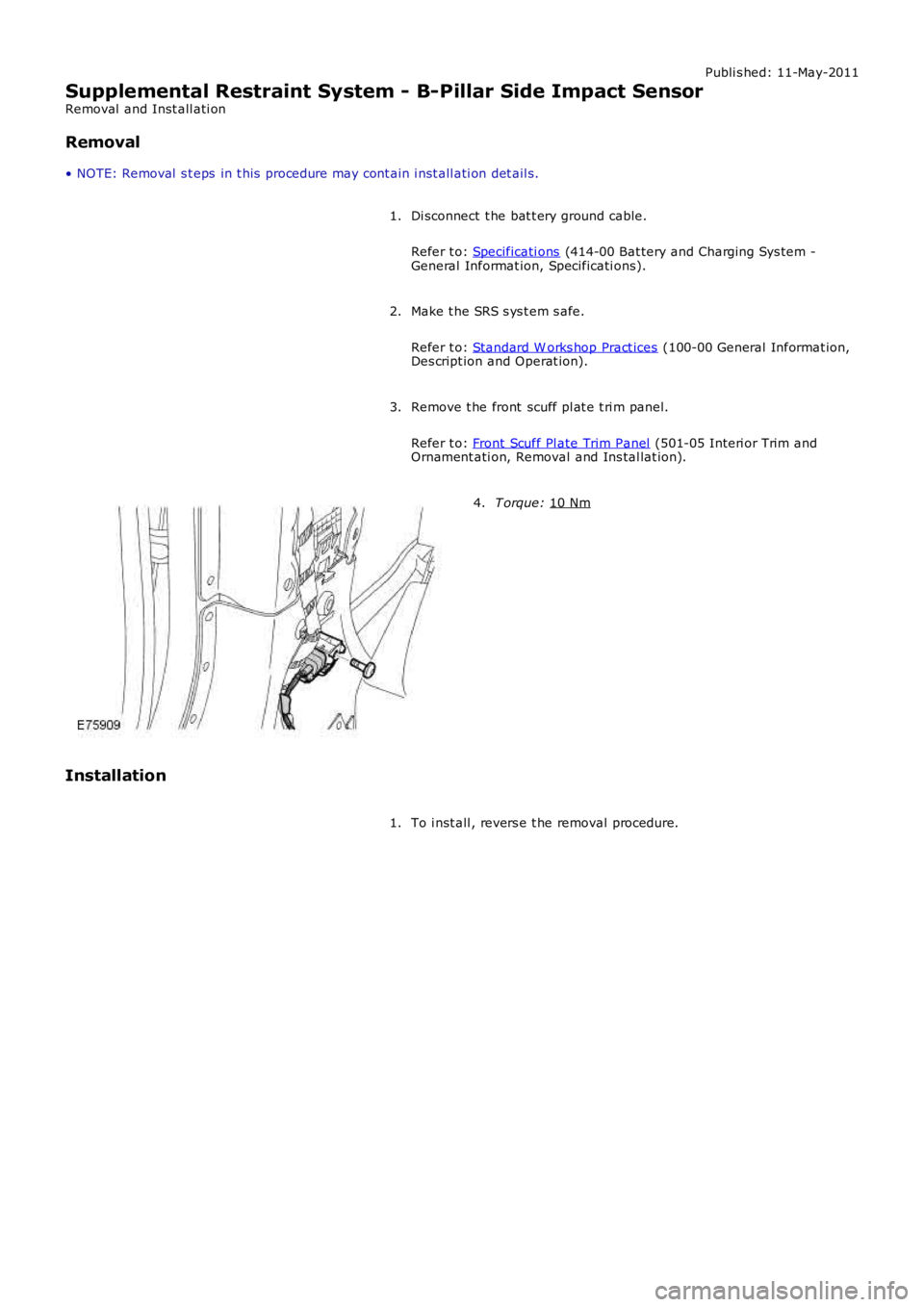
3. T orque:
10 Nm 4.
Installation To i nst all , revers e t he removal procedure.
1.
Page 2501 of 3229
Publi s hed: 11-May-2011
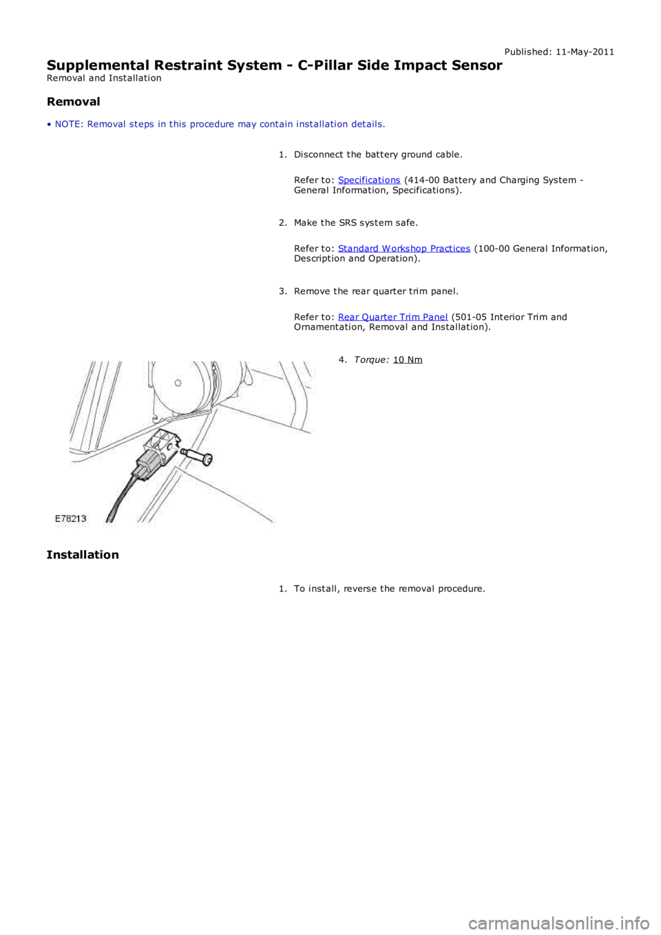
Supplemental Restraint System - C-Pillar Side Impact Sensor
Removal and Inst all ati on
Removal
• NOTE: Removal s t eps in t his procedure may cont ain i nst all ati on det ail s.
Di sconnect t he bat t ery ground cable.
Refer t o: Specificati ons (414-00 Bat tery and Charging Sys tem -
General Informat ion, Specificati ons).
1.
Make t he SRS s ys t em s afe.
Refer t o: Standard W orks hop Pract ices (100-00 General Informat ion,
Des cript ion and Operat ion).
2.
Remove t he rear quart er t ri m panel.
Refer t o: Rear Quarter Tri m Panel (501-05 Int erior Tri m and
Ornament ati on, Removal and Ins tal lat ion).
3. T orque:
10 Nm 4.
Installation To i nst all , revers e t he removal procedure.
1.
Page 2502 of 3229
Publi s hed: 11-May-2011
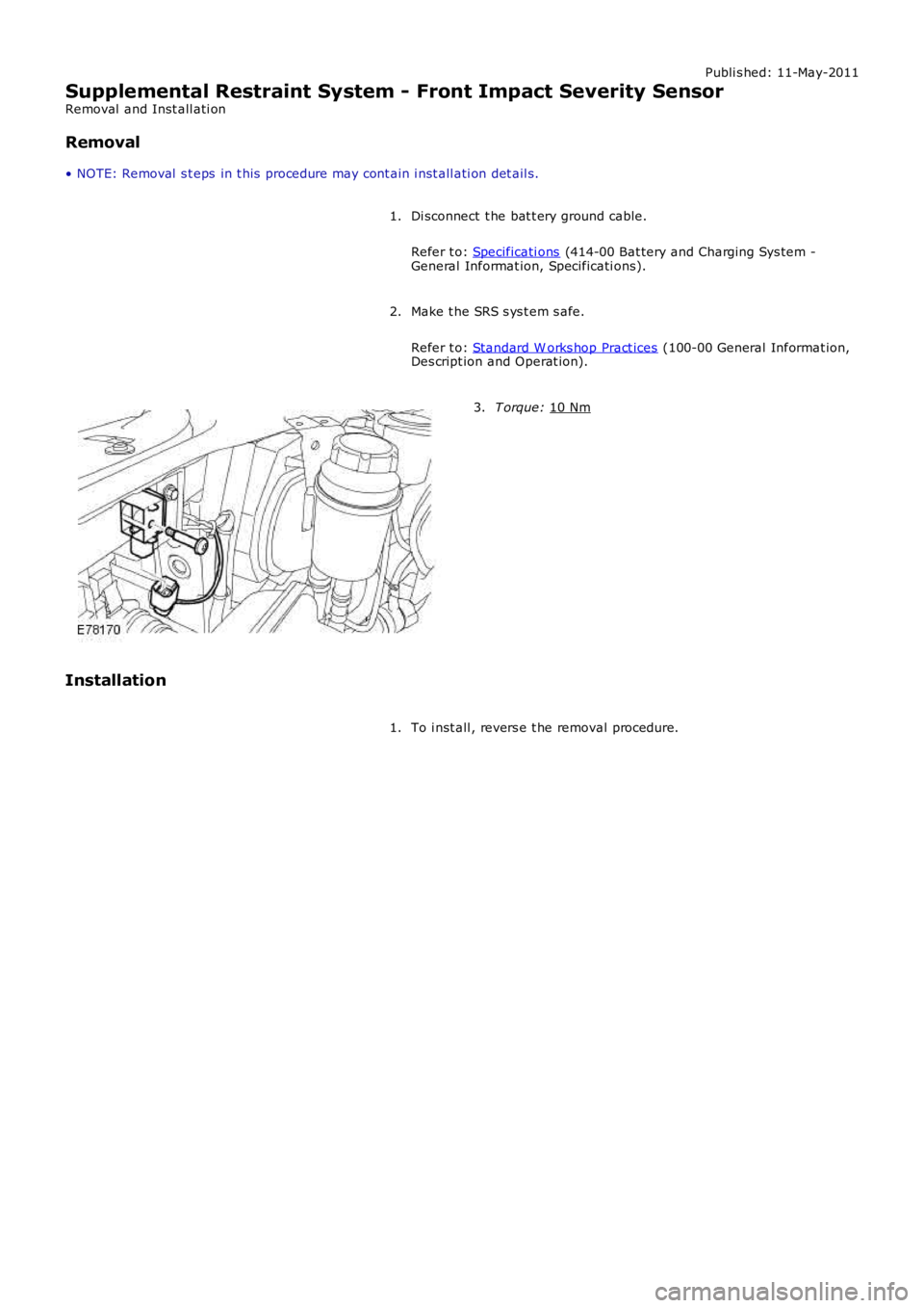
Supplemental Restraint System - Front Impact Severity Sensor
Removal and Inst all ati on
Removal
• NOTE: Removal s t eps in t his procedure may cont ain i nst all ati on det ail s.
Di sconnect t he bat t ery ground cable.
Refer t o: Specificati ons (414-00 Bat tery and Charging Sys tem -
General Informat ion, Specificati ons).
1.
Make t he SRS s ys t em s afe.
Refer t o: Standard W orks hop Pract ices (100-00 General Informat ion,
Des cript ion and Operat ion).
2. T orque:
10 Nm 3.
Installation To i nst all , revers e t he removal procedure.
1.
Page 2593 of 3229
Installation).
18. Remove the front seat.
Fo r a d d i t i o na l i nf o rma t i o n, re f e r t o : Front Seat
(501-10 Seat ing,
Removal and Installation).
19. Remove the floor console.
Fo r a d d i t i o na l i nf o rma t i o n, re f e r t o : Fl oor Cons ol e
(501-12
Instrument Panel and Console, Removal and Installation).
20. Remove the RH & LH rocker panel inner trims.
21. Remove the rear seat cushion.
Fo r a d d i t i o na l i nf o rma t i o n, re f e r t o : Rear Seat Cushion
(501-10
Seating, Removal and Installation).
22. Re mo ve t he re a r ca rp e t s e ct i o n.
23. Remove the B-Pillar side impact sensor.
Fo r a d d i t i o na l i nf o rma t i o n, re f e r t o : B-Pillar Side Impact Sensor
(501-20B Supplement al Res t raint Syst em, Removal and
Installation).
24. Remove the front safety belt retractor.
Fo r a d d i t i o na l i nf o rma t i o n, re f e r t o : Front Safety Belt Retractor
(501-20A Safet y Belt Sys t em, Removal and Ins t al lat ion).
25. Remove the rear safety belt retractor.
Fo r a d d i t i o na l i nf o rma t i o n, re f e r t o : Rear Safety Belt Retractor
(501-20A Safet y Belt Sys t em, Removal and Ins t al lat ion).
26. Release and lay aside the front carpet section.
27. Re mo ve t he re a r ca rp e t s e ct i o n.
28. Remove the front wheel and tire. LINK
29. Remove the rear wheel and tire.
Fo r a d d i t i o na l i nf o rma t i o n, re f e r t o : Wheel and Tire
(204-04
Wheels and Tires, Removal and Installation).
30. Remove the rocker panel out er mouldi ng.
31. Remove the liftgate aperture weatherseal.
32. Remove the forced air extraction grille.
33. Release and lay aside the insulating material at the inner
bulkhead.
34. Release and lay aside the insulating material at the inner quarter
panel.
35. Release and lay aside the wiring harnesses at the A-Pillar,
B-Pillar and rocker panel.
36. Release and lay aside the wiring harness along the inner quarter
panel and back panel.
37. Release and lay aside the insulating material at the inner quarter
panel.
38. RH side: Drain the fuel tank.
Fo r a d d i t i o na l i nf o rma t i o n, re f e r t o : Fuel Tank Draining
(310-00
Fuel Sys t em - General Informat ion, General Procedures).
39. RH side: Remove the fuel tank filler pipe.
Fo r a d d i t i o na l i nf o rma t i o n, re f e r t o : Fuel Tank Filler Pipe
(310-01A
Fuel Tank and Lines - I6 3.2L Petrol, Removal and Installation).
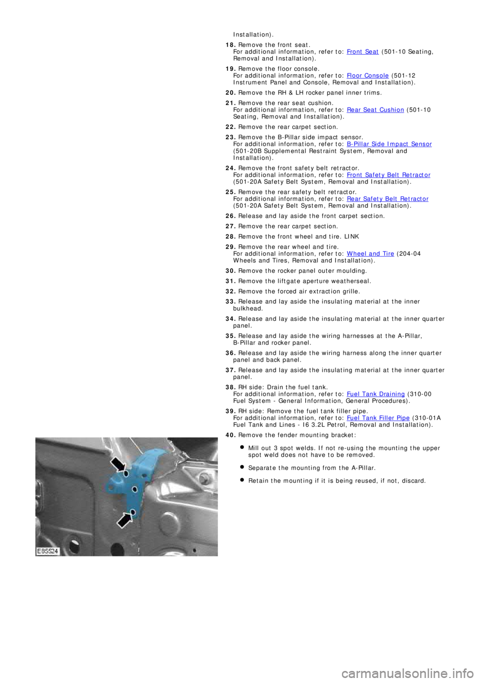
40. Remove the fender mounting bracket:
Mill out 3 spot welds. If not re-using the mounting the upper
spot weld does not have to be removed.
Separate the mounting from the A-Pillar.
Retain the mounting if it is being reused, if not, discard.
Page 2600 of 3229
Publ is hed: 11-May-2011
Side Panel Sheet Metal Repairs - Side Panel Front Section
Removal and Installation
Removal
CAUTION: The side panel front section must be MIG slot brazed to its reinforcement, which contains DP600, (Dual
Phase steel). MIG plug we lds / spot w elds, must not be use d.
• NOTE: The side panel front section is serviced as a separate weld on panel, serviced less the fender mounting bracket,
which is serviced separately.
• NOTE: There are NVH elements attached inside this panel, they are not serviced on the new panel. If damaged, new
element/s will be required.
1. The s ide panel front s ect ion is replaced in conjunct ion wit h:
Front bumper cover
Front fender
Hood
Front door
Rear door
Instrument panel
Windshield glass
Headliner
2. Fo r a d d i t i o na l i nf o rma t i o n re l a t i ng t o t hi s re p a i r p ro ce d ure
please see the following:
Fo r a d d i t i o na l i nf o rma t i o n, re f e r t o : Body and Frame
(501-26
Body Repairs - Vehicle Specific Information and Tolerance
Checks, Description and Operation) /
St a nd a rd W o rks ho p P ra ct i ce s
(100-00 Ge ne ra l I nf o rma t i o n,
Description and Operation).
3. Remove the hood.
4. Remove the front fender.
5. Remove the front door.
Fo r a d d i t i o na l i nf o rma t i o n, re f e r t o : Front Door
(501-03 Body
Closures, Removal and Installation).
6. Remove the rear door.
Fo r a d d i t i o na l i nf o rma t i o n, re f e r t o : Rear Door
(501-03 Body
Closures, Removal and Installation).
7. Remove the headliner.
Fo r a d d i t i o na l i nf o rma t i o n, re f e r t o : Headliner - Vehicles
Without: Tilting Roof Opening Panel (501-05 Int eri or Tri m and
Ornamentation, Removal and Installation) /
Headliner - Vehicles With: Tilting Roof Opening Panel
(501-05
Int erior Trim and Ornamentat ion, Removal and Installat ion).
8. Re move t he i ns t rume nt pa ne l .
Fo r a d d i t i o na l i nf o rma t i o n, re f e r t o : Instrument Panel - TD4
2.2L Di es el (501-12 Ins t rument Panel and Cons ole, Removal
and Installation).
9. Remove the windshield glass.
Fo r a d d i t i o na l i nf o rma t i o n, re f e r t o : Windshield Glass
(501-11
Glass, Frames and Mechanisms, Removal and Installation).
10. Remove the upper and lower door hinges from the A-Pillar, 4
x bol t s .
11. Remove the upper and lower door hinges from the B-Pillar, 4
x bol t s .
12. Remove the front door striker from the B-Pillar.
13. Re mo ve t he s i d e a i r curt a i n mo d ul e .
Fo r a d d i t i o na l i nf o rma t i o n, re f e r t o : Si d e A i r Curt a i n Mo d ul e
(501-20B Suppl ement al Res t rai nt Sys t em, Removal and
Installation).
14. Remove the rear seat cushion.
Fo r a d d i t i o na l i nf o rma t i o n, re f e r t o : Rear Seat Cushion
(501-10
Seating, Removal and Installation).
15. Remove the RH & LH rocker panel inner trims.
16. Remove the B-Pillar side impact sensor.
Fo r a d d i t i o na l i nf o rma t i o n, re f e r t o : B-Pillar Side Impact Sensor