2006 LAND ROVER FRELANDER 2 sensor
[x] Cancel search: sensorPage 1810 of 3229
Publi s hed: 11-May-2011
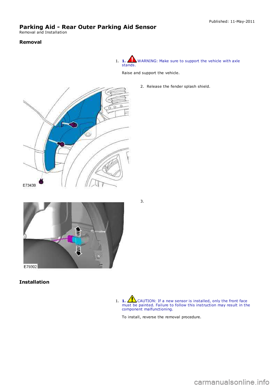
Parking Aid - Rear Outer Parking Aid Sensor
Removal and Inst all ati on
Removal
1. W ARNING: Make sure t o s upport the vehicle wit h axles tands .
Rais e and s upport t he vehi cl e.
1.
Releas e t he fender spl as h shi el d.2.
3.
Installation
1. CAUTION: If a new s ensor i s ins t al led, only t he front facemus t be paint ed. Fail ure t o foll ow t hi s ins t ructi on may res ult in t hecomponent mal funct ioni ng.
To i nst all , revers e t he removal procedure.
1.
Page 1864 of 3229
1
1
1
1
1
1
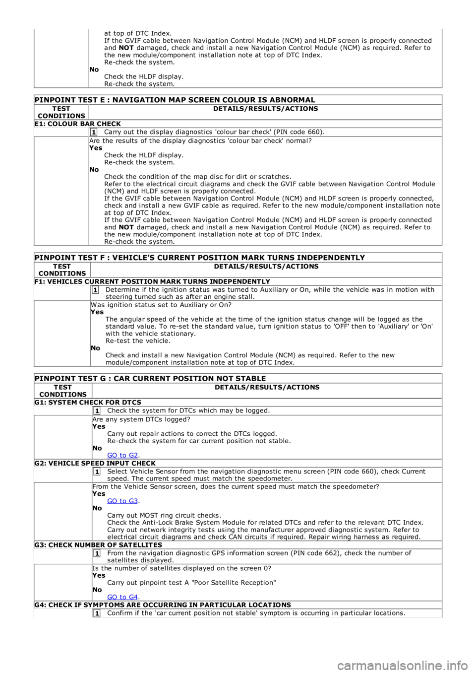
at t op of DTC Index.If the GVIF cable bet ween Navi gat ion Cont rol Modul e (NCM) and HLDF s creen is properly connect edand NOT damaged, check and i nst all a new Navi gat ion Cont rol Module (NCM) as required. Refer tot he new module/component ins tal lati on note at t op of DTC Index.Re-check the s ys tem.NoCheck the HLDF di spl ay.Re-check the s ys tem.
PINPOINT TEST E : NAVIGATION MAP SCREEN COLOUR IS ABNORMAL
T ESTCONDIT IONSDET AILS/RESULT S/ACT IONS
E1: COLOUR BAR CHECK
Carry out the di s pl ay diagnost ics 'colour bar check' (PIN code 660).
Are the res ul ts of t he dis play di agnos ti cs 'colour bar check' normal ?YesCheck the HLDF di spl ay.Re-check the s ys tem.NoCheck the condit ion of t he map dis c for di rt or s crat ches .Refer t o t he electrical ci rcuit diagrams and check t he GVIF cable bet ween Navigati on Cont rol Module(NCM) and HLDF s creen is properly connect ed.If the GVIF cable bet ween Navi gat ion Cont rol Modul e (NCM) and HLDF s creen is properly connect ed,check and i nst all a new GVIF cable as required. Refer t o t he new module/component ins tal lati on noteat t op of DTC Index.If the GVIF cable bet ween Navi gat ion Cont rol Modul e (NCM) and HLDF s creen is properly connect edand NOT damaged, check and i nst all a new Navi gat ion Cont rol Module (NCM) as required. Refer tot he new module/component ins tal lati on note at t op of DTC Index.Re-check the s ys tem.
PINPOINT TEST F : VEHICLE’S CURRENT POSITION MARK TURNS INDEPENDENTLY
T ESTCONDIT IONSDET AILS/RESULT S/ACT IONS
F1: VEHICLES CURRENT POSIT ION MARK T URNS INDEPENDENT LY
Det ermi ne if t he ignit ion st atus was turned to Auxil iary or On, whi le the vehicle was in moti on wit hs t eering t urned s uch as aft er an engi ne s tall .
W as ignit ion s t at us s et to Auxi liary or On?YesThe angular s peed of t he vehi cl e at t he ti me of t he igni ti on st atus change wil l be logged as t hes t andard val ue. To re-s et t he s tandard value, t urn i gni ti on s tat us to 'OFF' t hen t o 'Auxil iary' or 'On'wi th the vehicle st ati onary.Re-tes t the vehicle.NoCheck and ins tal l a new Navigati on Cont rol Module (NCM) as requi red. Refer t o t he newmodule/component ins tal lati on note at top of DTC Index.
PINPOINT TEST G : CAR CURRENT POSITION NOT STABLE
T ESTCONDIT IONSDET AILS/RESULT S/ACT IONS
G1: SYST EM CHECK FOR DT CS
Check the sys tem for DTCs whi ch may be l ogged.
Are any s ys t em DTCs l ogged?YesCarry out repair act ions to correct the DTCs logged.Re-check the sys tem for car current pos it ion not s table.NoGO to G2.
G2: VEHICLE SPEED INPUT CHECK
Select Vehicle Sens or from t he navi gat ion di agnos ti c menu s creen (PIN code 660), check Currents peed. The current speed mus t mat ch the speedometer.
From t he Vehi cl e Sensor s creen, does t he current s peed mus t mat ch the s peedomet er?YesGO to G3.NoCarry out MOST ring ci rcuit checks .Check the Ant i-Lock Brake Sys t em Module for rel at ed DTCs and refer to the relevant DTC Index.Carry out network int egrit y t est s us ing t he manufacturer approved di agnos ti c s ys t em. Refer toel ect ri cal circuit di agrams and check CAN circuit s i f required. Repair wi ring harness as required.
G3: CHECK NUMBER OF SAT ELLIT ES
From t he navi gat ion di agnos ti c GPS i nformat ion screen (PIN code 662), check t he number ofs atel li tes dis played.
Is t he number of s atel lit es dis played on t he s creen 0?YesCarry out pinpoint t est A "Poor Satell it e Recept ion"NoGO to G4.G4: CHECK IF SYMPT OMS ARE OCCURRING IN PART ICULAR LOCAT IO NS
Confi rm if t he 'car current pos it ion not s table' s ymptom is occurring i n part icular locati ons .
Page 1932 of 3229
Publi s hed: 11-May-2011
Exterior Lighting - Headlamps
Diagnosi s and Tes ti ng
Principles of Operation
For a detail ed descripti on of the ext erior l ighti ng s ys t em, refer to t he Des cript ion and Operat ion secti on 417-00 - Ext eriorLighti ng of the workshop manual.
Safety Information
• W ARNINGS:
The Xenon Headl amp s ys tem generat es up t o 28,000 volt s . Make sure t hat t he headl amps are swit ched off beforeworki ng on the sys tem. Fai lure to foll ow t his i ns t ructi on may l ead to fat al it y.
The followi ng s afety precaut ions mus t be fol lowed when working on t he Xenon Headl amp Sys tem:
DO NOT att empt any procedures on t he Xenon Headlamps or circui ts when the sys tem is energi zed.Handl ing of t he xenon bul b mus t be performed us i ng sui table protect ive equipment, e.g. gl oves and goggles . Theglas s part of t he bulb mus t not be t ouched.Only operat e t he lamp in a mounted condit ion i n t he reflect or.All s afet y procedures and precaut ions mus t be foll owed to prevent pers onal injury.
CAUTION: Xenon bulbs mus t be dis pos ed of as hazardous was te.
There are ins t ructi ons on the correct procedures for Xenon Headlamp Sys t em repai rs in t he manual, refer to secti on 100-00- General Informat ion, Standard W orks hop Pract ices of t he works hop manual .
Inspection And Verification
CAUTION: Di agnos is by s ubs ti tut ion from a donor vehicle is NO T acceptabl e. Subs ti tut ion of cont rol modules doesnot guarant ee confirmat ion of a faul t, and may als o caus e addit ional fault s i n t he vehi cl e being t est ed and/or t he donorvehi cl e.
1. Verify t he cus t omer concern.
Note that int ermi tt ent fault report s may be due t o t he cycli ng operati on of the fi eld effect trans is t ors (FETs )
1.
2. Vis ually ins pect for obvious mechani cal or electrical fault s .2.
Visual Inspection Chart
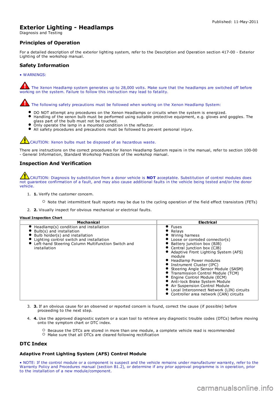
MechanicalElectricalHeadlamp(s) condit ion and i ns t allat ionBulb(s) and ins tall ati onBulb hol der(s ) and i nst all at ionLight ing cont rol s wi tch and i ns t allat ionLeft -hand St eering Col umn Mult ifunct ion Swi tch andi ns t allat ion
Fus esRel aysW iring harnes sLoos e or corroded connector(s )Bat tery juncti on box (BJB)Cent ral juncti on box (CJB)Adapt ive Front Lighti ng Syst em (AFS)modul eHeadlamp Power modul esIns trument Clus ter (IPC)St eeri ng Angl e Sensor Module (SASM)Transmis si on Control Module (TCM)Engine Cont rol Module (ECM)Ant i-lock Brake Sys tem Modul eAi r Suspens ion Control Modul eLocal Int erconnect Net work (LIN) ci rcuit sCont roll er area network (CAN) ci rcuit s
3. If an obvious cause for an obs erved or report ed concern is found, correct t he caus e (if pos s ible) beforeproceeding t o t he next s t ep.3.
4. Us e the approved di agnos ti c s ys t em or a s can t ool t o ret rieve any diagnos t ic t rouble codes (DTCs ) before movingont o t he sympt om chart or DTC i ndex.
Becaus e t he DTCs are st ored i n more t han one modul e, a complete vehi cl e read i s recommendedMake s ure t hat all DTCs are cl eared fol lowing recti fi cat ion
4.
DTC Index
Adaptive Front Lighting System (AFS) Control Module
• NOTE: If the control modul e or a component i s s us pect and the vehicle remains under manufacturer warrant y, refer t o theW arranty Pol icy and Procedures manual (s ect ion B1.2), or determine i f any pri or approval programme is in operat ion, pri ort o the ins tall ati on of a new module/component.
Page 2070 of 3229
8-TCM
9-Engi ne Cont rol Module (ECM)
10-Diagnos t ic s ocket11-Occupant Cl ass i fi cat ion Sensor (OCS - NAS onl y
COMPONENT LOCATION - MOST
Page 2161 of 3229
(Ignit ion). The forward facing light s ensor moni tors the ambi ent light l evel at the front of t he vehi cl e; the rearward facingli ght sens or moni tors t he li ght l evel coming from t he rear of the vehicle. W hen li ght from the rear of the vehicle exceedst he ambient li ght l evel from the front of t he vehi cl e, the aut omat ic di mmi ng circuit darkens t he i nt eri or mirror s urface.
Automat ic di mmi ng is i nhi bit ed when revers e gear is sel ect ed to provide t he dri ver wi th maximum vis ion. On vehicles wi thautomat ic t rans mis s ion, t he revers e gear s ignal i s provided by t he TCM vi a t he high s peed Cont rol ler Area Net work (CAN)bus to the CJB. The CJB then provi des a power feed t o t he mirror. On vehicles wi th manual t rans mis s ion, the revers e gears ignal is provi ded by a t ransmis s ion s wit ch t hat i s hardwi red t o t he CJB.
Cabin Humidity Sensor
Dependi ng on the vehicl e s pecificati on, t he automat ic di mmi ng int erior mirror may als o i ncorporate a cabi n humidi tys ens or. The cabin humi dit y s ens or is locat ed i n the mirror rear cas ing near to the wi nds hiel d, and provi des the ATC modul ewit h i nformati on regarding the probabil it y of winds hield mis t ing. Thi s i nformat ion is us ed to vary t he automat ic operat ionof the cl imat e cont rol s yst em.For addit ional informat ion, refer t o: Cont rol Component s (412-01 Cli mat e Cont rol , Descripti on and Operat ion).
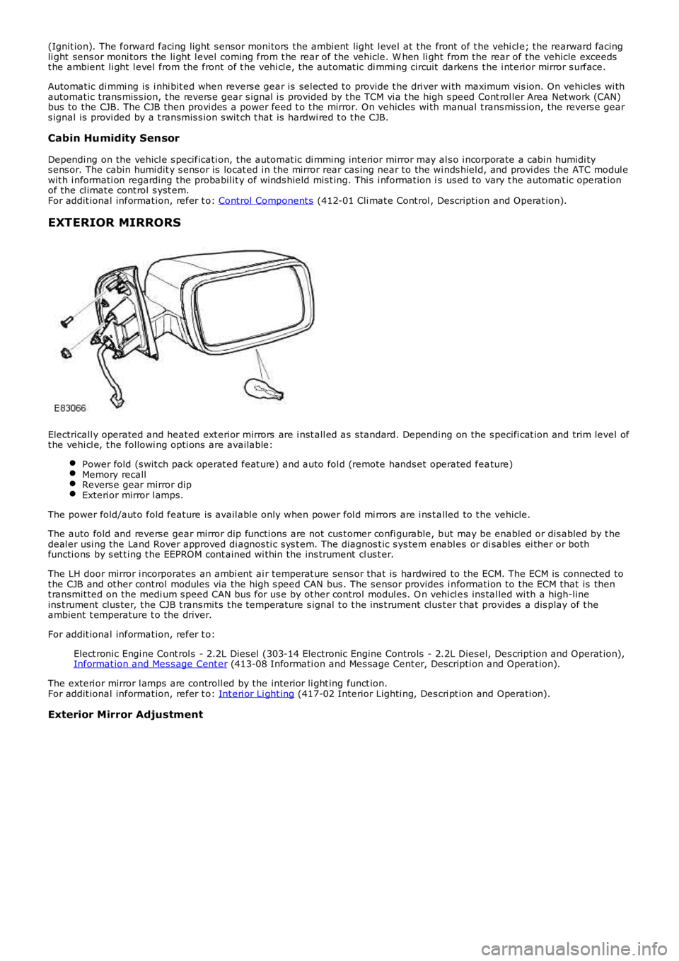
EXTERIOR MIRRORS
Electricall y operated and heated ext eri or mirrors are i nst all ed as s tandard. Depending on the s pecifi cat ion and trim level oft he vehi cl e, t he followi ng opti ons are available:
Power fold (s wit ch pack operat ed feat ure) and auto fol d (remote hands et operated feature)Memory recallRevers e gear mirror dipExteri or mirror l amps.
The power fold/aut o fold feature is avail abl e only when power fol d mi rrors are i ns t alled to t he vehicle.
The auto fold and revers e gear mirror dip functi ons are not cus t omer confi gurable, but may be enabled or dis abled by t hedeal er usi ng the Land Rover approved di agnos ti c s ys t em. The diagnos t ic s ys tem enabl es or di sabl es ei ther or bothfuncti ons by s et t ing t he EEPROM cont ained wi thin the ins trument cl us t er.
The LH door mirror i ncorporat es an ambi ent ai r temperat ure sens or that is hardwired to the ECM. The ECM is connected tot he CJB and ot her cont rol modules via the hi gh s peed CAN bus . The s ensor provides i nformati on to the ECM that is thent ransmit ted on the medi um s peed CAN bus for us e by ot her control modul es. O n vehi cl es ins tal led wi th a high-lineins t rument clus ter, t he CJB t rans mit s t he temperature s ignal t o t he ins t rument clus ter t hat provi des a dis play of t heambient t emperature t o the driver.
For addit ional informat ion, refer t o:
Elect roni c Engi ne Cont rol s - 2.2L Dies el (303-14 Electronic Engine Controls - 2.2L Dies el, Des cript ion and Operat ion),Informat ion and Mes s age Cent er (413-08 Informati on and Mes sage Cent er, Descripti on and Operat ion).
The exteri or mirror l amps are controll ed by the interior li ght ing funct ion.For addit ional informat ion, refer t o: Int eri or Li ght ing (417-02 Interior Lighti ng, Des cri pt ion and Operati on).
Exterior Mirror Adjustment
Page 2347 of 3229
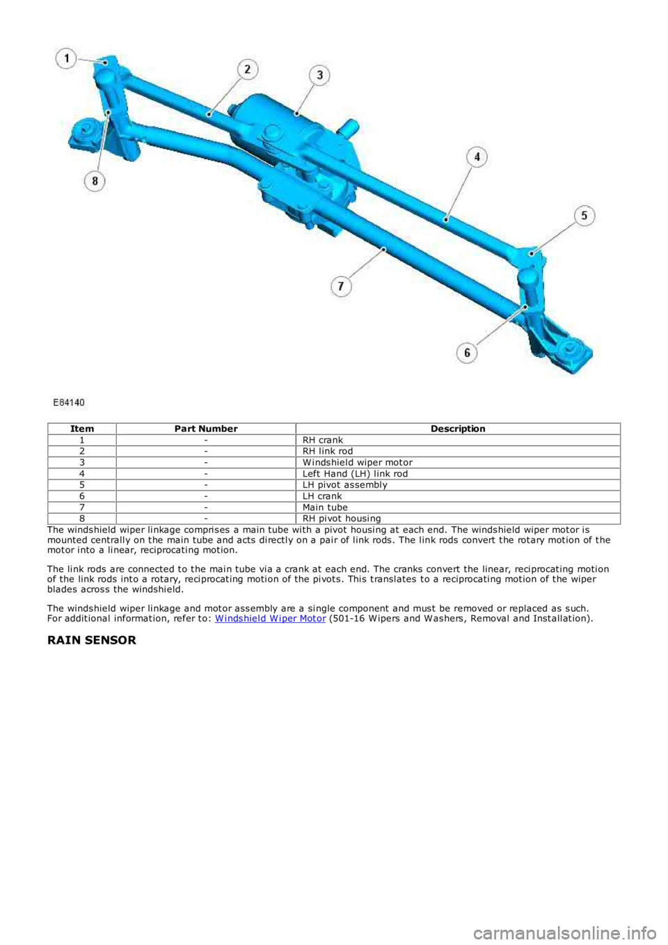
ItemPart NumberDescription
1-RH crank2-RH l ink rod
3-W i nds hiel d wiper mot or
4-Left Hand (LH) l ink rod5-LH pivot as sembl y
6-LH crank
7-Main tube8-RH pi vot housi ng
The winds hield wiper li nkage compri s es a main tube wi th a pivot housi ng at each end. The winds hield wiper mot or i smounted centrall y on t he main tube and acts di rectl y on a pai r of l ink rods . The l ink rods convert t he rot ary mot ion of t hemot or i nto a li near, reciprocati ng mot ion.
The li nk rods are connected t o t he mai n tube vi a a crank at each end. The cranks convert the linear, reci procat ing moti onof the link rods int o a rotary, reci procat ing moti on of the pi vot s . Thi s t ransl ates t o a reciprocati ng mot ion of t he wiperblades acros s the windshi eld.
The winds hield wiper li nkage and mot or ass embly are a si ngle component and mus t be removed or replaced as s uch.For addit ional informat ion, refer t o: W i nds hiel d W i per Mot or (501-16 W ipers and W as hers , Removal and Inst all at ion).
RAIN SENSOR
Page 2357 of 3229
Publi s hed: 11-May-2011
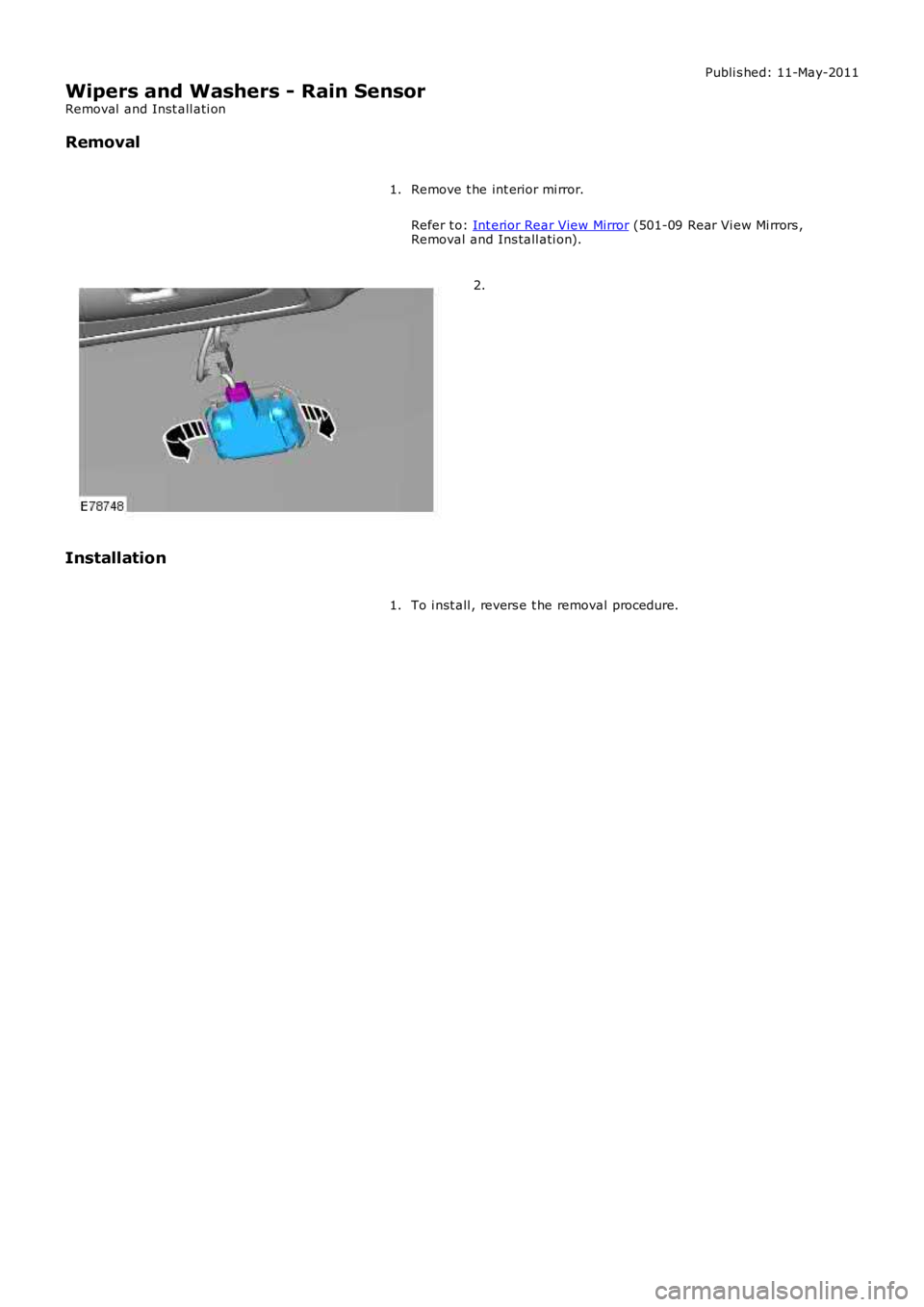
Wipers and Washers - Rain Sensor
Removal and Inst all ati on
Removal
Remove t he int erior mi rror.
Refer t o: Int erior Rear View Mirror (501-09 Rear Vi ew Mi rrors ,Removal and Ins tall ati on).
1.
2.
Installation
To i nst all , revers e t he removal procedure.1.
Page 2453 of 3229
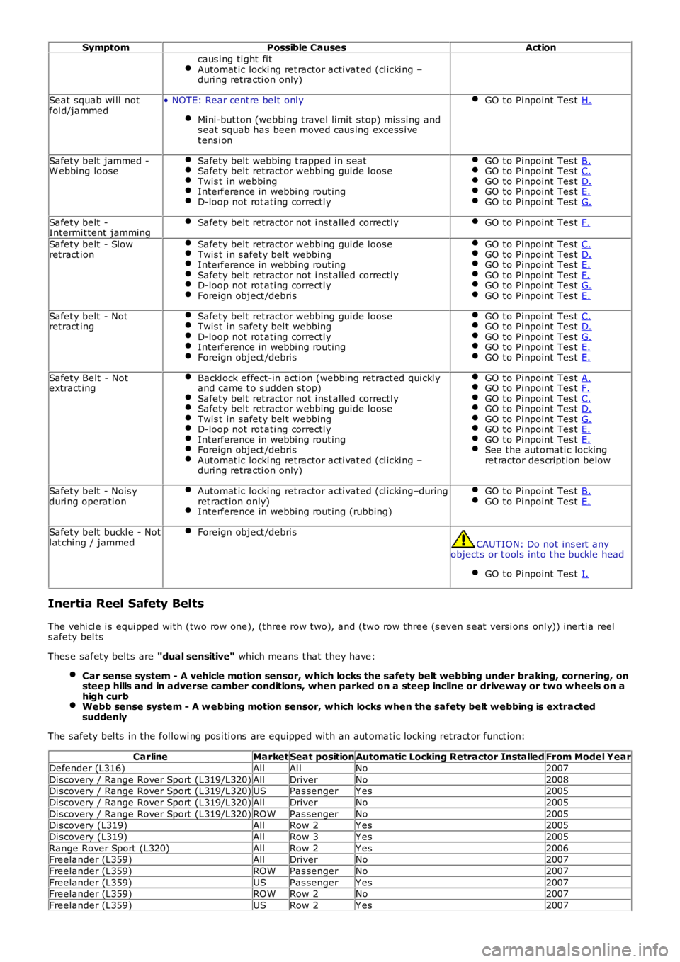
SymptomPossible CausesAction
caus i ng ti ght fitAutomat ic locki ng ret ractor acti vat ed (cl icki ng –duri ng ret racti on only)
Seat squab wi ll notfol d/jammed• NOTE: Rear cent re bel t onl y
Mi ni -but ton (webbing t ravel limit s t op) mis si ng ands eat squab has been moved caus ing excess i vet ens i on
GO t o Pi npoint Tes t H.
Safet y belt jammed -W ebbing looseSafet y belt webbing t rapped in s eatSafet y belt ret ract or webbing gui de loos eTwis t i n webbingInterference in webbi ng rout ingD-loop not rot ati ng correctl y
GO t o Pi npoint Tes t B.GO t o Pi npoint Tes t C.GO t o Pi npoint Tes t D.GO t o Pi npoint Tes t E.GO t o Pi npoint Tes t G.
Safet y belt -Intermit tent jammingSafet y belt ret ract or not i ns t alled correctl yGO t o Pi npoint Tes t F.
Safet y belt - Slowret ract ionSafet y belt ret ract or webbing gui de loos eTwis t i n s afet y bel t webbingInterference in webbi ng rout ingSafet y belt ret ract or not i ns t alled correctl yD-loop not rot ati ng correctl yForeign object /debri s
GO t o Pi npoint Tes t C.GO t o Pi npoint Tes t D.GO t o Pi npoint Tes t E.GO t o Pi npoint Tes t F.GO t o Pi npoint Tes t G.GO t o Pi npoint Tes t E.
Safet y belt - Notret ract ingSafet y belt ret ract or webbing gui de loos eTwis t i n s afet y bel t webbingD-loop not rot ati ng correctl yInterference in webbi ng rout ingForeign object /debri s
GO t o Pi npoint Tes t C.GO t o Pi npoint Tes t D.GO t o Pi npoint Tes t G.GO t o Pi npoint Tes t E.GO t o Pi npoint Tes t E.
Safet y Belt - Notextract ingBackl ock effect-in act ion (webbing ret ract ed qui ckl yand came t o s udden st op)Safet y belt ret ract or not i ns t alled correctl ySafet y belt ret ract or webbing gui de loos eTwis t i n s afet y bel t webbingD-loop not rot ati ng correctl yInterference in webbi ng rout ingForeign object /debri sAutomat ic locki ng ret ractor acti vat ed (cl icki ng –duri ng ret racti on only)
GO t o Pi npoint Tes t A.GO t o Pi npoint Tes t F.GO t o Pi npoint Tes t C.GO t o Pi npoint Tes t D.GO t o Pi npoint Tes t G.GO t o Pi npoint Tes t E.GO t o Pi npoint Tes t E.See the aut omati c lockingret ractor des cript ion below
Safet y belt - Nois yduri ng operati onAutomat ic locki ng ret ractor acti vat ed (cl icki ng–duringret ract ion only)Interference in webbi ng rout ing (rubbing)
GO t o Pi npoint Tes t B.GO t o Pi npoint Tes t E.
Safet y belt buckl e - Notl at chi ng / jammedForeign object /debri s
CAUTION: Do not ins ert anyobject s or t ool s int o t he buckle head
GO t o Pi npoint Tes t I.
Inertia Reel Safety Belts
The vehi cl e i s equi pped wit h (two row one), (t hree row t wo), and (two row three (s even s eat versi ons onl y)) i nerti a reels afety bel ts
Thes e safet y belt s are "dual sensitive" which means t hat t hey have:
Car sense system - A vehicle motion sensor, w hich locks the safety belt webbing under braking, cornering, onsteep hills and in adverse camber conditions, when parked on a steep incline or driveway or two w heels on ahigh curbWebb sense system - A w ebbing motion sensor, w hich locks when the safety belt w ebbing is extractedsuddenly
The s afety bel ts in t he fol lowi ng pos i ti ons are equipped wit h an aut omati c locking ret ract or funct ion:
CarlineMarketSeat positionAutomatic Locking Retractor InstalledFrom Model Year
Defender (L316)AllAl lNo2007
Di scovery / Range Rover Sport (L319/L320)AllDriverNo2008Di scovery / Range Rover Sport (L319/L320)USPas sengerY es2005
Di scovery / Range Rover Sport (L319/L320)AllDriverNo2005
Di scovery / Range Rover Sport (L319/L320)ROWPas sengerNo2005Di scovery (L319)AllRow 2Y es2005
Di scovery (L319)AllRow 3Y es2005
Range Rover Sport (L320)AllRow 2Y es2006Freelander (L359)AllDriverNo2007
Freelander (L359)ROWPas sengerNo2007
Freelander (L359)USPas sengerY es2007Freelander (L359)ROWRow 2No2007
Freelander (L359)USRow 2Y es2007