2006 LAND ROVER FRELANDER 2 lock
[x] Cancel search: lockPage 2468 of 3229
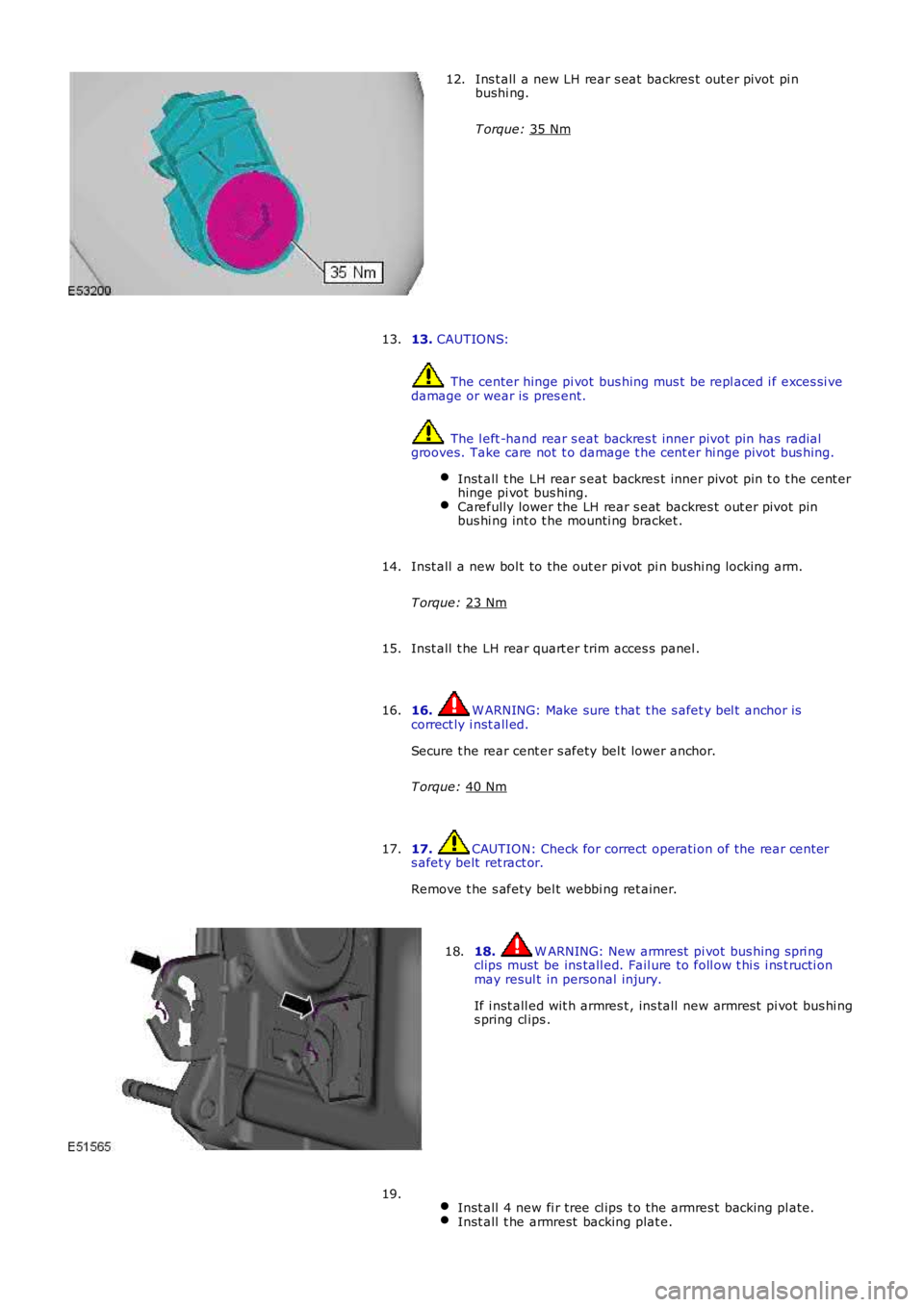
Ins t all a new LH rear s eat backres t out er pivot pi n
bushi ng.
T orque: 35 Nm 12.
13. CAUTIONS: The center hinge pi vot bus hing mus t be repl aced i f exces si ve
damage or wear is pres ent. The l eft -hand rear s eat backres t inner pivot pin has radial
grooves. Take care not t o damage t he cent er hi nge pivot bus hing.
Inst all t he LH rear s eat backres t inner pivot pin t o t he cent er
hinge pi vot bus hing. Carefully lower the LH rear s eat backres t out er pivot pin
bus hi ng int o t he mounti ng bracket . 13.
Inst all a new bol t to the out er pi vot pi n bushi ng locking arm.
T orque: 23 Nm 14.
Inst all t he LH rear quart er trim acces s panel .
15.
16. W ARNING: Make sure t hat t he s afet y bel t anchor is
correct ly i nst all ed.
Secure t he rear cent er s afety bel t lower anchor.
T orque: 40 Nm 16.
17. CAUTION: Check for correct operati on of the rear cent er
s afet y belt ret ract or.
Remove t he s afety bel t webbi ng ret ainer.
17. 18. W ARNING: New armrest pi vot bus hing s pri ng
clips must be ins tall ed. Fail ure to foll ow t hi s i ns t ructi on
may resul t in personal injury.
If i nst all ed wit h armres t , ins tall new armres t pi vot bus hi ng
s pring cl ips .
18.
Inst all 4 new fi r tree cl ips t o t he armres t backing pl ate. Inst all t he armrest backing plat e.19.
Page 2469 of 3229
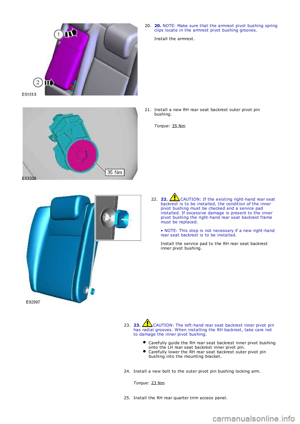
20.
NOTE: Make sure t hat t he armres t pivot bus hing spring
clips locat e i n t he armrest pi vot bus hing grooves .
Ins t all the armrest .
20. Ins t all a new RH rear s eat backres t out er pivot pin
bushi ng.
T orque: 35 Nm 21.
22. CAUTION: If the exis t ing right-hand rear s eat
backrest i s t o be i ns t alled, t he condit ion of t he i nner
pivot bushi ng mus t be checked and a s ervice pad
i ns t alled. If excess i ve damage is pres ent t o the inner
pivot bushi ng the ri ght -hand rear s eat backres t frame
mus t be repl aced.
• NOTE: This st ep is not necess ary if a new ri ght -hand
rear s eat backres t is to be ins tal led.
Inst all t he s ervice pad t o t he RH rear s eat backres t
i nner pivot bushi ng.
22.
23. CAUTION: The left-hand rear s eat backres t inner pi vot pi n
has radi al grooves . W hen i ns t alli ng t he RH backrest , take care not
t o damage t he inner pi vot bus hing.
Carefully gui de the RH rear s eat backres t inner pivot bus hing
onto the LH rear s eat backres t inner pi vot pi n. Carefully lower the RH rear s eat backres t outer pivot pin
bus hi ng int o t he mounti ng bracket . 23.
Inst all a new bol t to the out er pi vot pi n bushi ng locking arm.
T orque: 23 Nm 24.
Inst all t he RH rear quart er trim acces s panel .
25.
Page 2474 of 3229
Publi s hed: 11-May-2011
Supplemental Restraint System - Air Bag and Safety Belt Pretensioner
Supplemental Restraint System (SRS)
Des cript ion and Operat ion
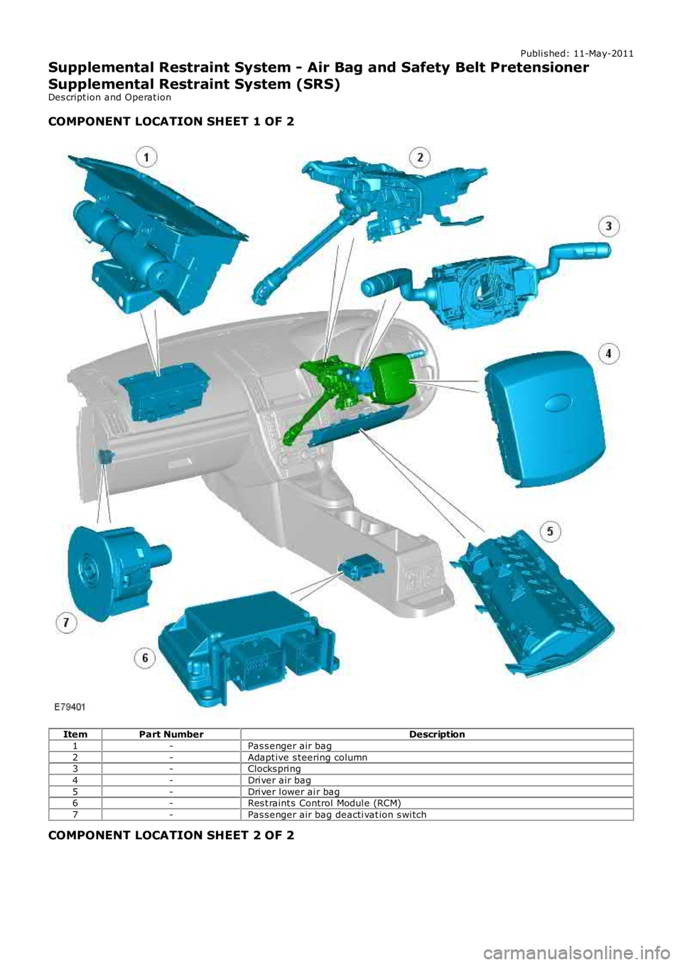
COMPONENT LOCATION SHEET 1 OF 2
ItemPart NumberDescription
1-Pas s enger air bag
2-Adapt ive s teering column3-Clocks pri ng
4-Dri ver air bag
5-Dri ver l ower ai r bag6-Res t raint s Control Modul e (RCM)
7-Pas s enger air bag deacti vat ion s wi tch
COMPONENT LOCATION SHEET 2 OF 2
Page 2478 of 3229
12-Seat pos i ti on sens or
13-Pas senger ai r bag deact ivati on s wit ch
14-Driver safety belt buckle s wi tch15-Pas senger safety belt buckle s wi tch
16-Impact s ens or - l eft -hand front
17-Impact s ens or - right -hand front18-Side impact sens or - left -hand B-pil lar
19-Side impact sens or - ri ght -hand B-pill ar
20-Side impact sens or - left -hand C-pil lar21-Side impact sens or - ri ght -hand C-pill ar
22-Driver lower air bag
23-Adapti ve st eeri ng col umn24-Side ai r bag – l eft-hand
25-Side ai r bag – right-hand
26-Clockspring27-Pas senger ai r bag
28-Driver ai r bag
29-Curt ain ai r bag – l eft-hand30-Curt ain ai r bag – right-hand
PRINCIPLES OF OPERATION
Crash Sensing
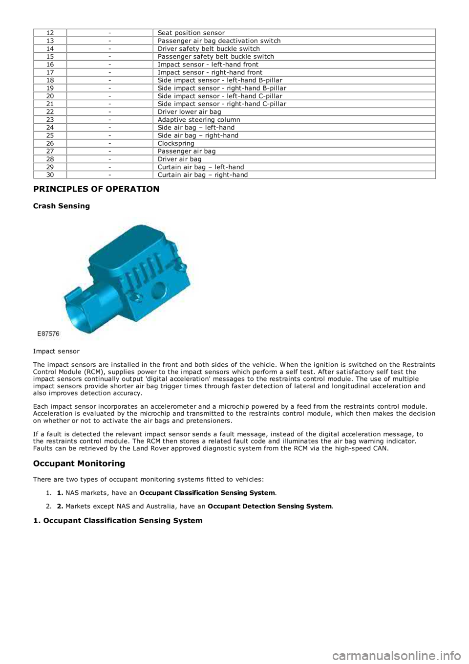
Impact s ensor
The impact s ens ors are i nst all ed in the front and both si des of the vehicle. W hen the i gni ti on is swi tched on t he Res trai ntsControl Module (RCM), s uppli es power to t he i mpact s ensors which perform a s elf t es t. After s ati sfact ory sel f tes t theimpact s ens ors cont inually out put 'digi tal accelerat ion' mes s ages t o t he res t raint s cont rol module. The us e of mult ipl eimpact s ens ors provide s hort er ai r bag trigger ti mes t hrough fas t er det ect ion of l ateral and l ongit udinal accelerat ion andals o i mproves detecti on accuracy.
Each impact sens or incorporat es an acceleromet er and a mi crochi p powered by a feed from the res traints cont rol module.Accelerati on is evaluat ed by the microchip and t rans mi tt ed t o the res traints cont rol module, which t hen makes the decis ionon whether or not to act ivate the ai r bags and pretens ioners .
If a fault is detect ed the relevant impact sens or sends a fault mes s age, i ns t ead of the di gi tal accel erati on mes s age, t ot he res traint s cont rol module. The RCM t hen s tores a rel ated fault code and il luminat es the ai r bag warning indicator.Faul ts can be ret rieved by t he Land Rover approved diagnos t ic s ys tem from t he RCM via t he high-s peed CAN.
Occupant Monitoring
There are t wo t ypes of occupant monit oring s ys tems fi tt ed to vehi cl es:
1. NAS market s , have an O ccupant Classification Sensing System.1.
2. Markets except NAS and Aust ral ia, have an Occupant Detection Sensing System.2.
1. Occupant Classification Sensing System
Page 2483 of 3229
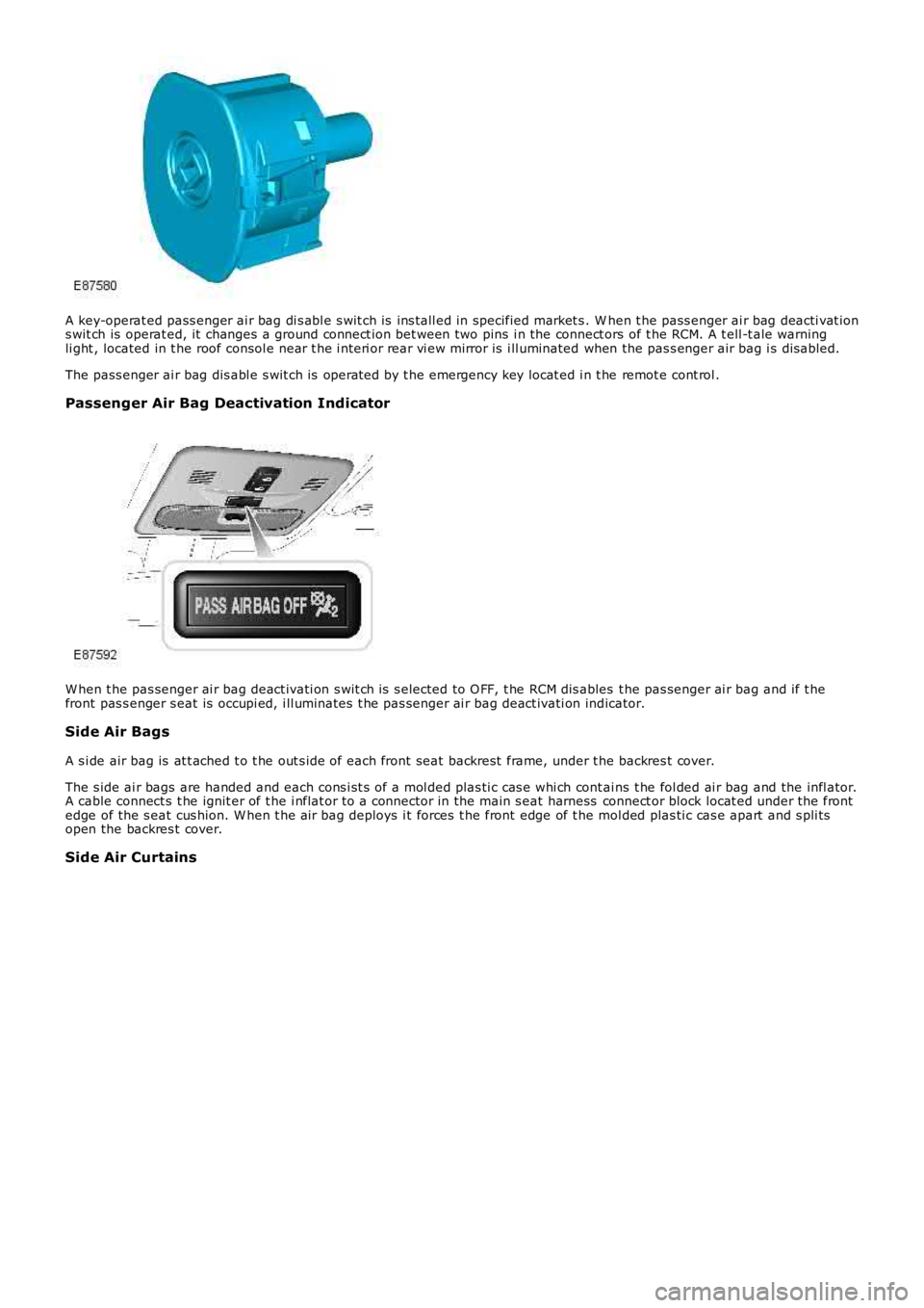
A key-operat ed pass enger ai r bag di s abl e s wit ch is ins tall ed in specified market s . When t he pass enger ai r bag deacti vat ions wit ch is operat ed, it changes a ground connect ion bet ween two pins i n the connect ors of t he RCM. A t ell -t ale warningli ght , located in t he roof consol e near t he i nt eri or rear vi ew mirror is i ll uminated when the pas s enger air bag i s dis abled.
The pass enger ai r bag dis abl e s wit ch is operat ed by t he emergency key locat ed i n t he remot e cont rol .
Passenger Air Bag Deactivation Indicator
W hen t he pas senger ai r bag deact ivati on s wit ch is s elected to O FF, t he RCM dis ables t he pas senger ai r bag and if t hefront pas s enger s eat is occupi ed, i ll uminates t he pas senger ai r bag deact ivati on indicator.
Side Air Bags
A s i de air bag is at t ached t o t he out s ide of each front seat backrest frame, under the backres t cover.
The s ide ai r bags are handed and each cons i st s of a mol ded plas ti c cas e whi ch cont ains t he fol ded ai r bag and the infl ator.A cable connect s t he ignit er of t he i nflat or to a connector in the main s eat harness connect or block locat ed under the frontedge of the s eat cus hion. W hen t he air bag deploys i t forces t he front edge of t he mol ded plas ti c cas e apart and s pli tsopen the backres t cover.
Side Air Curtains
Page 2484 of 3229
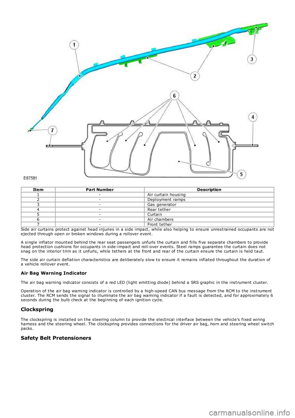
ItemPart NumberDescription
1-Air curt ai n housi ng2-Depl oyment ramps
3-Gas generat or
4-Rear t ether5-Curtai n
6-Air chambers
7-Front tet herSide ai r curtains protect agai nst head i njuri es in a s ide i mpact , whil e als o helpi ng to ens ure unres trai ned occupant s are notejected through open or broken wi ndows during a roll over event .
A s i ngl e inflat or mount ed behi nd t he rear s eat pas s engers unfurl s the curtain and fills fi ve separat e chambers t o providehead prot ect ion cushi ons for occupant s i n s ide-i mpact and roll -over event s. St eel ramps guarantee t he curt ain does nots nag on the interior t ri m as i t unfurl s , whi le tet hers at t he front and rear of t he curt ain ens ure t he curt ain i s held t aut.
The s ide ai r curtain deflat ion characteris ti cs are deli beratel y s low t o ens ure i t remai ns inflated throughout the durat ion ofa vehicle roll over event .
Air Bag Warning Indicator
The air bag warni ng indi cat or cons is ts of a red LED (li ght emit ti ng diode) behi nd a SRS graphic in t he i ns t rument clus ter.
Operat ion of t he air bag warni ng indicator i s cont rol led by a hi gh-s peed CAN bus mess age from t he RCM t o t he ins t rumentclus ter. The RCM s ends t he s ignal to il luminat e t he air bag warni ng indicator i f a faul t is det ect ed, and for approxi matel y 6s econds duri ng the bul b check at t he begi nni ng of each i gnit ion cycl e.
Clockspring
The clocks pri ng is ins tall ed on t he s teeri ng column t o provi de the el ect ri cal i nt erface bet ween t he vehi cl e's fixed wiringharnes s and the st eering wheel . The cl ocks pring provides connecti ons for the driver air bag, horn and s teering wheel swit chpacks .
Safety Belt Pretensioners
Page 2498 of 3229
Publi s hed: 11-May-2011
Supplemental Restraint System - Clockspring
Removal and Inst all ati on
Removal
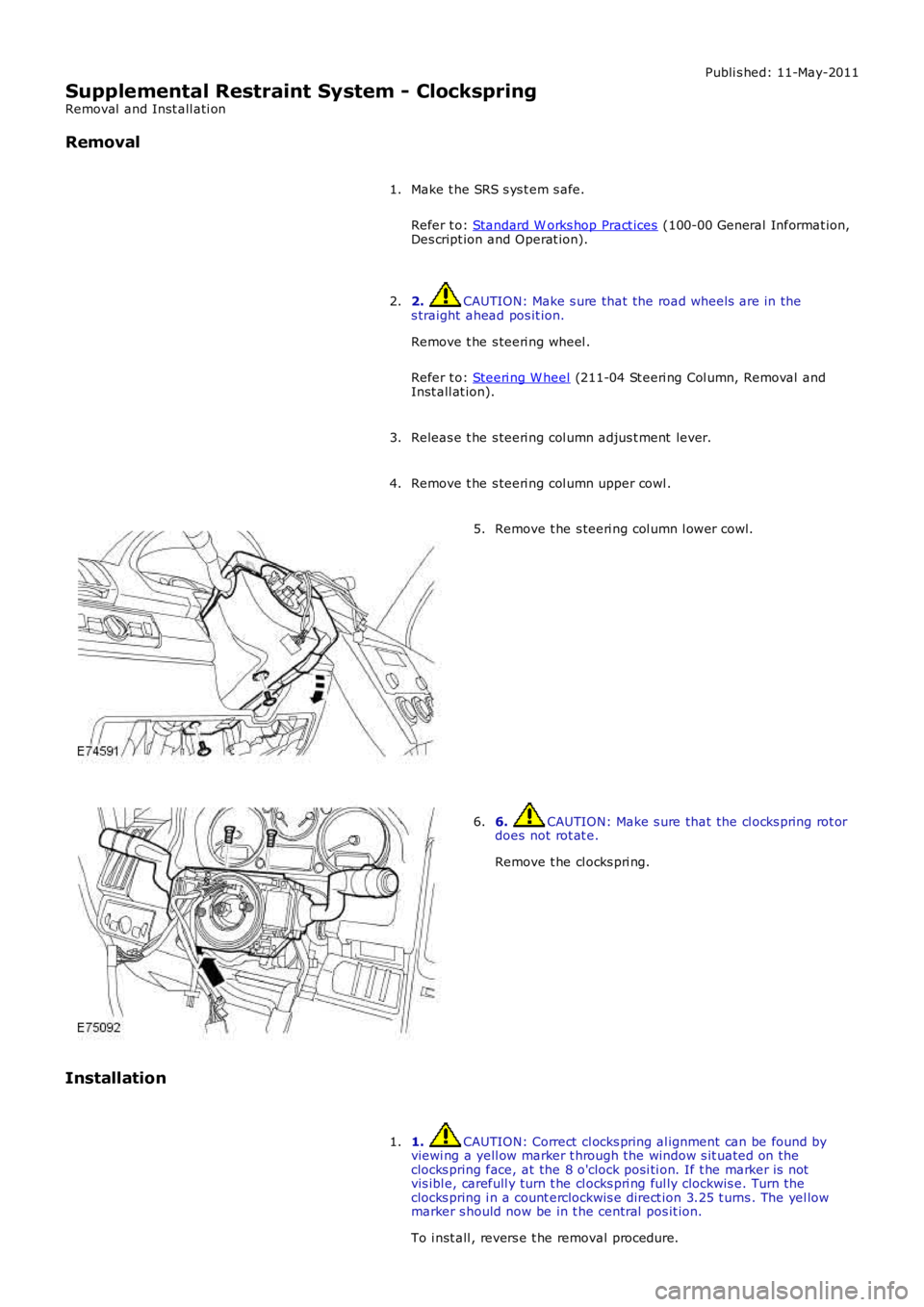
Make t he SRS s ys t em s afe.
Refer t o: Standard W orks hop Pract ices (100-00 General Informat ion,Des cript ion and Operat ion).
1.
2. CAUTION: Make s ure that the road wheels are in thes traight ahead pos it ion.
Remove t he s teeri ng wheel .
Refer t o: Steeri ng W heel (211-04 St eeri ng Col umn, Removal andInst all at ion).
2.
Releas e t he s teeri ng col umn adjus t ment lever.3.
Remove t he s teeri ng col umn upper cowl .4.
Remove t he s teeri ng col umn l ower cowl.5.
6. CAUTION: Make s ure that the cl ocks pring rot ordoes not rot at e.
Remove t he cl ocks pri ng.
6.
Installation
1. CAUTION: Correct cl ocks pring al ignment can be found byviewi ng a yell ow marker t hrough the window s it uated on theclocks pring face, at the 8 o'clock posi ti on. If t he marker is notvis ibl e, carefull y turn t he cl ocks pri ng ful ly clockwis e. Turn t heclocks pring i n a count erclockwis e direct ion 3.25 t urns . The yel lowmarker s hould now be in t he central pos it ion.
To i nst all , revers e t he removal procedure.
1.
Page 2510 of 3229
In addi ti on t o the short st roke s aw, t he reciprocati ng s aw can be us ed. W it h t his , it i s poss i bl e t o make narrow ands traight cut s t o an exact depth.
Carrying out the repairs
Butt joint
• NOTE: The s everance cut s houl d always be kept as s hort as poss i bl e on s ecti onal repl acement. Onl y cut at t he s everanceli nes shown in t he repair chapters.
Do not make any cuts near rei nforcements or pre-determined folding lines .
Prepare parts remaini ng on t he vehi cl e/new parts .- Res hape t he adjoi ni ng s urface of any dented body part s t hat are t o remai n on t he vehicle us ing a hammer anda count erhold (ens ure t hat the ol d part mat ches the s hape of the new part ). Grind off left over s pot wel ds ors eams wit h an angle grinder.- Cut the new part s to s hape.- If neces sary punch or drill holes for mig plug wel di ng.-• NOTE: Do not us e a wel ding t orch t o remove pai nt res idue (the heat coul d caus e t he met al to deform).
Gri nd all joining flanges to bare met al on both s i des . Do not us e an angle grinder for t hi s purpos e (this couldweaken the met al and damage the zi nc layer). Sui table tools : rot ati ng wi re brush, belt s ander or plas t ic dis c.- Apply wel di ng pri mer li berall y to all weld flanges .- The pri mer mus t be well s t irred before us e.
• NOTE: W hen us ing aerosol s, t ake care not t o cont aminat e adjacent part s wi th spray mi st .
Fit t he new part .
It must be ens ured that t he new part fit s exact ly t o t he s pecified di mensi ons. Suit able equipment :- Ali gnment jig.- Univers al meas uring s ys tem.- Jig s ys tem.- Ruler or tape meas ure.- Compass .- Frame dimens ions can be found i n t he model-specific repai r manual s.• NOTE: Any att ached body part s t hat require accurat e ali gnment and fit t ing mus t be i ncorporat ed i n t hi s s tep; forins t ance bumpers , s eal s , headlamps , rear l amps and lock as sembl y components . If thi s is not done careful ly i t mayres ult i n wat er l eaks , wi nd noi s es and subs tant ial fol low-on work.
Ensure t hat edges li ne up wi th adjacent part s and check t hat gaps are cons is t ent (compare l eft and right-hands ides ). Make s ure that the shape of t he vehi cl e is ret ai ned.
Secure t he new part
• NOTE: The need for s ubsequent foll ow-on work can be s ignificantl y reduced if ali gni ng and t ack-wel ding arecarri ed out wit h due care.
Dependi ng on acces si bili ty the foll owing met hods for s ecuri ng are avai lable: