Page 2775 of 3229

55
Seat belts
R
Seat belt checks
Note: If the vehicle is parked on an incline, the
seat belt mechanism may lock. This is not a
fault, and the belt shoul d be gently eased out
from the upper anchorage.
The seat belts should be inspected regularly to
check for fraying, cuts, or wear to the webbing,
and the condition and security of the
mechanism, buckles, adjusters, and mounting
points.
Checks
• With the seat belt fastened, give the
webbing near the buckle a quick upward
pull. The buckle must remain securely
locked.
• With the seat belt unfastened, unreel the
seat belt to the limit of its travel. Check that
it unreels smoothly with no snatches or
snags. Allow the belt to fully retract, again
checking for smooth operation.
• Partially unreel the seat belt, then hold the
tongue plate and give a quick forward pull.
The mechanism must lock and prevent any
further unreeling.
If any of the seat belts fail to meet those
criteria, immediately contact you Land Rover
Dealer/Authorised Repairer.
SEAT BELT REMINDER
If the driver's se at belt is not
fastened when the vehicle is in
motion, a chime will be heard and
the seat belt warning i ndicator will illuminate.
The warning chime and indicator will also be
activated if the front passenger seat is
occupied without the seat belt being fastened.
Note: Objects placed on the front passenger
seat may activate the seat belt reminder
warning chime and indicator. It is
recommended that any objects placed on the
front passenger seat are secured using the seat
belt.
Care must be
taken to avoid
contaminating the seat belt webbing,
and seat belt mechanisms with any
chemicals, liquids, gr it, dirt, or cleaning
products. If the seat belts do become
contaminated they should be replaced
immediately. Contaminated seat belts my not
operate correctly in an impact and cannot be
relied upon.
WARNINGS
Page 2776 of 3229

Seat belts
56
L
FASTENING THE SEAT BELTS
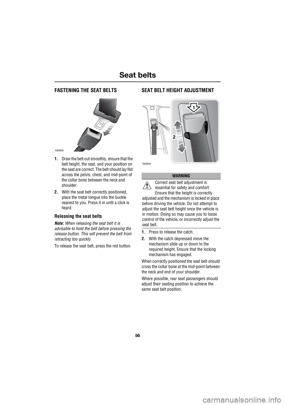
1. Draw the belt out smoothly, ensure that the
belt height, the seat, and your position on
the seat are correct. The belt should lay flat
across the pelvis, chest, and mid-point of
the collar bone between the neck and
shoulder.
2. With the seat belt correctly positioned,
place the metal tongue into the buckle
nearest to you. Press it in until a click is
heard.
Releasing the seat belts
Note: When releasing the seat belt it is
advisable to hold the belt before pressing the
release button. This will prevent the belt from
retracting too quickly.
To release the seat be lt, press the red button.
SEAT BELT HEIGHT ADJUSTMENT
1.Press to release the catch.
2. With the catch depressed move the
mechanism slide up or down to the
required height. Ensure that the locking
mechanism has engaged.
When correctly positione d the seat belt should
cross the collar bone at the mid-point between
the neck and end of your shoulder.
Where possible, rear se at passengers should
adjust their seating position to achieve the
same seat belt position.
E82905
WARNING
Correct seat belt adjustment is
essential for safe ty and comfort.
Ensure that the hei ght is correctly
adjusted and the mechanism is locked in place
before driving the vehicl e. Do not attempt to
adjust the seat belt height once the vehicle is
in motion. Doing so ma y cause you to loose
control of the vehicle, or incorrectly adjust the
seat belt.
E82904
2
1
Page 2788 of 3229

Child safety
68
L
ISOFIX child seats
• IUF = Suitable for ISOFIX forward child
restraint systems of universal category
approved for use in the mass group.
• IL = These ISOFIX child restraint systems
are of the specific vehicle, restricted, or
semi-universal categories.
• * = Child seats suitable for use in these
locations are Britax Cosy-Tot, and Römer
Baby Safe ISOFIX.
Installing an ISOFIX child seat
To install an ISOFIX child seat :-
1. Raise or remove the head restraint.
2. Lift the velcro flap to expose the ISOFIX
locking mechanism.
3. Slide the child seat into the locking
mechanism.
4. Test the security of the child restraint. To
do this attempt to pull the restraint away
from the vehicle seat and twist the restraint
from side to side. Even if the restraint
appears secure you should still check the
anchor points visually to ensure correct
attachment.
Note: Always ensure that if an upper tether is
provided, it is fitted and tightened correctly.
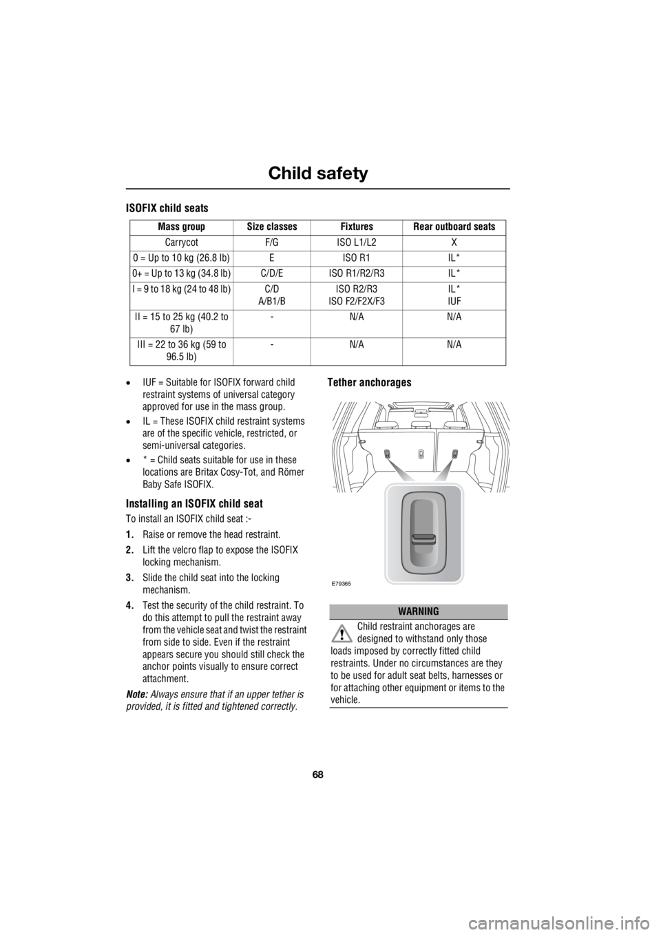
Tether anchorages
Mass group Size classes Fixtures Rear outboard seats
Carrycot F/G ISO L1/L2 X
0 = Up to 10 kg (26.8 lb) E ISO R1 IL*
0+ = Up to 13 kg (34.8 lb) C/D/E ISO R1/R2/R3 IL*
I = 9 to 18 kg (24 to 48 lb) C/D A/B1/B ISO R2/R3
ISO F2/F2X/F3 IL*
IUF
II = 15 to 25 kg (40.2 to 67 lb) -N/A N/A
III = 22 to 36 kg (59 to 96.5 lb) -N/A N/A
WARNING
Child restraint anchorages are
designed to withstand only those
loads imposed by correctly fitted child
restraints. Under no circumstances are they
to be used for adult se at belts, harnesses or
for attaching other equipment or items to the
vehicle.
E79365
Page 2789 of 3229
69
Child safety
R
Tether anchorages are provided at each rear
outboard seating position.
Note: A tether anchorage is provided for the
centre seat position, but should only be used
when a non- ISOFIX child seat with a tether is
used in this seating position.
CHILD SAFETY LOCKS
Child safety locks are fitted to the rear doors to
allow you to prevent accidental opening of the
doors when the vehicle is in motion.
If children are to be carried in the rear seat
positions, it is recomme nded that the rear door
interior handles are disabled.
Note: For convenience the rear door interior
handles should be re-e nabled when carrying
adult passengers in th e rear seat positions.
To change the child lock settings :-
1. Open the door to access the child safety
lock.
2. Insert the emergency key into the slot, and
rotate a quarter of a turn to enable, or
disable the interior door handle as
required.
E83601
1
2
Page 2790 of 3229
Steering wheel
70
L
Steering wheelADJUSTING THE STEERING WHEEL
To adjust the steering wheel :-
1. Release the locking mechanism by pulling
the lever down.
2. Adjust the steering wheel to the desired
position.
3. Push the locking lever back up, and ensure
that it's fully home.
AUDIO CONTROL
1. Press to switch between radio, CD, or AUX.
2. Press to increase volume.
3. Press to decrease volume.
4. Press and release to scroll through preset
radio stations or CD tracks. Press to
search up or down for the next or previous
radio station/CD track.WARNINGS
Never adjust the steering wheel
position whilst the ve hicle is in motion.
Doing so will reduce control of the
vehicle, and may cause unpredictable steering
movements.
After adjusting the steering wheel
position, ensure that the locking lever
is returned to the fully up position.
Failure to do so will reduce control of the
vehicle, and may cause unpredictable steering
movements.
E82965
3
1
2
1
2
3
4
E83208
Page 2792 of 3229

Lighting
72
L
LightingLIGHTING CONTROL
Main switch panel
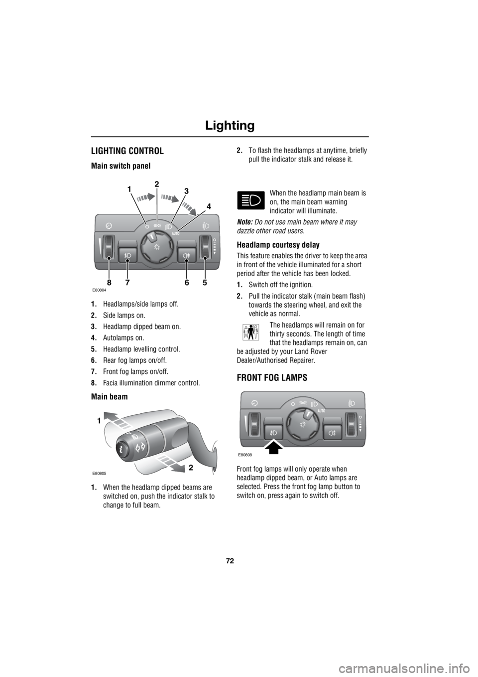
1. Headlamps/side lamps off.
2. Side lamps on.
3. Headlamp dipped beam on.
4. Autolamps on.
5. Headlamp levelling control.
6. Rear fog lamps on/off.
7. Front fog lamps on/off.
8. Facia illumination dimmer control.
Main beam
1.When the headlamp dipped beams are
switched on, push the indicator stalk to
change to full beam. 2.
To flash the headlamps at anytime, briefly
pull the indicator stalk and release it.
When the headlamp main beam is
on, the main beam warning
indicator will illuminate.
Note: Do not use main beam where it may
dazzle other road users.
Headlamp courtesy delay
This feature enables the driver to keep the area
in front of the vehicle illuminated for a short
period after the vehicle has been locked.
1. Switch off the ignition.
2. Pull the indicator stalk (main beam flash)
towards the steering wheel, and exit the
vehicle as normal.
The headlamps will remain on for
thirty seconds. The length of time
that the headlamps remain on, can
be adjusted by your Land Rover
Dealer/Authorised Repairer.
FRONT FOG LAMPS
Front fog lamps will only operate when
headlamp dipped beam, or Auto lamps are
selected. Press the front fog lamp button to
switch on, press again to switch off.
E808047865
123
4
1
2E80805
E80808
Page 2798 of 3229
Lighting
78
L
Removing the headlamp unit
In order to change a headlamp unit bulb, you
must first remove the headlamp unit.
To remove the headlamp unit :-
1. Undo and remove the two retaining bolts.
2. Pull up the locking lever to release the
headlamp unit.
3. Pull the headlamp unit forward sufficiently
to allow access to the rear of the unit.
4. Disconnect the electrical plug from the
back of the headlamp by pressing in the
locking tab and pulling the connector out.
1
3
4
1
E80991
2
1
CAUTION
Do not place the la mp unit face down
on hard or abrasive surfaces. Doing so
may scratch the surface of the lens.
Page 2799 of 3229
79
Lighting
R
Headlamp unit bulbs
Xenon dipped/main beam with
supplementary halogen main beam With the headlamp unit removed :-
1. Unclip the locking lever, press down the
two tabs and remove the cover.
2. Undo the two retaining screws and remove
the Xenon unit.
3. Remove the electrical connection from the
Xenon unit.
4. Pull the halogen main beam electrical
connector off of the supplementary
halogen main beam bulb.
5. Unclip the halogen bulb and remove it
from the unit.
2
4
2
5
3
E80994
1
2