2006 LAND ROVER FRELANDER 2 lock
[x] Cancel search: lockPage 2904 of 3229
Wheels and tyres
184
L
Wheel changing safety
Before raising the vehicl e, or changing a wheel
ensure that you read, and comply with the
following warnings.
WARNINGS
Always find a safe pl ace to stop, off of
the highway and away from traffic.
Ensure that the vehicle is on firm level
ground.
Disconnect traile r/caravan from
vehicle.
Switch on the hazard warning lamps.
Ensure that all passengers, and
animals, are out of the vehicle, and in a
safe place away from the highway.
Place a warning triangle at a suitable
distance behind th e vehicle, facing
towards oncoming traffic.
Ensure that the front wheels are in the
straight ahead positi on, and engage the
steering lock.
Apply the parking br ake, and engage
Park in vehicles fitted with an automatic
transmission.
Apply the parking br ake, and engage
1st or reverse gear in vehicles fitted
with a manual transmission.
Ensure that the jack is on firm level
ground.
Never place anything between the jack
and the ground, or the jack and the
vehicle.
Always chock the whee ls using suitable
wheel chocks. Place the chocks on both
sides of the wheel diagonally opposite the
wheel to be changed.
If jacking the vehicle on a slight slope is
unavoidable, place the chocks on the
downhill side of the two opposite wheels.
Take care when lifting the spare wheel,
and removing the punctured wheel. The
wheels are heavy, and ca n cause injuries if not
handled correctly.
Remove the spare wheel prior to
jacking the vehicle. To avoid
destabilising the vehicle when raised.
Take care when loosening the wheel
nuts. The wheel brace may slip off if not
properly attached, and the wheel nuts may
give way suddenly. Either unexpected
movement may cause an injury.
WARNINGS
Page 2905 of 3229
185
Wheels and tyres
R
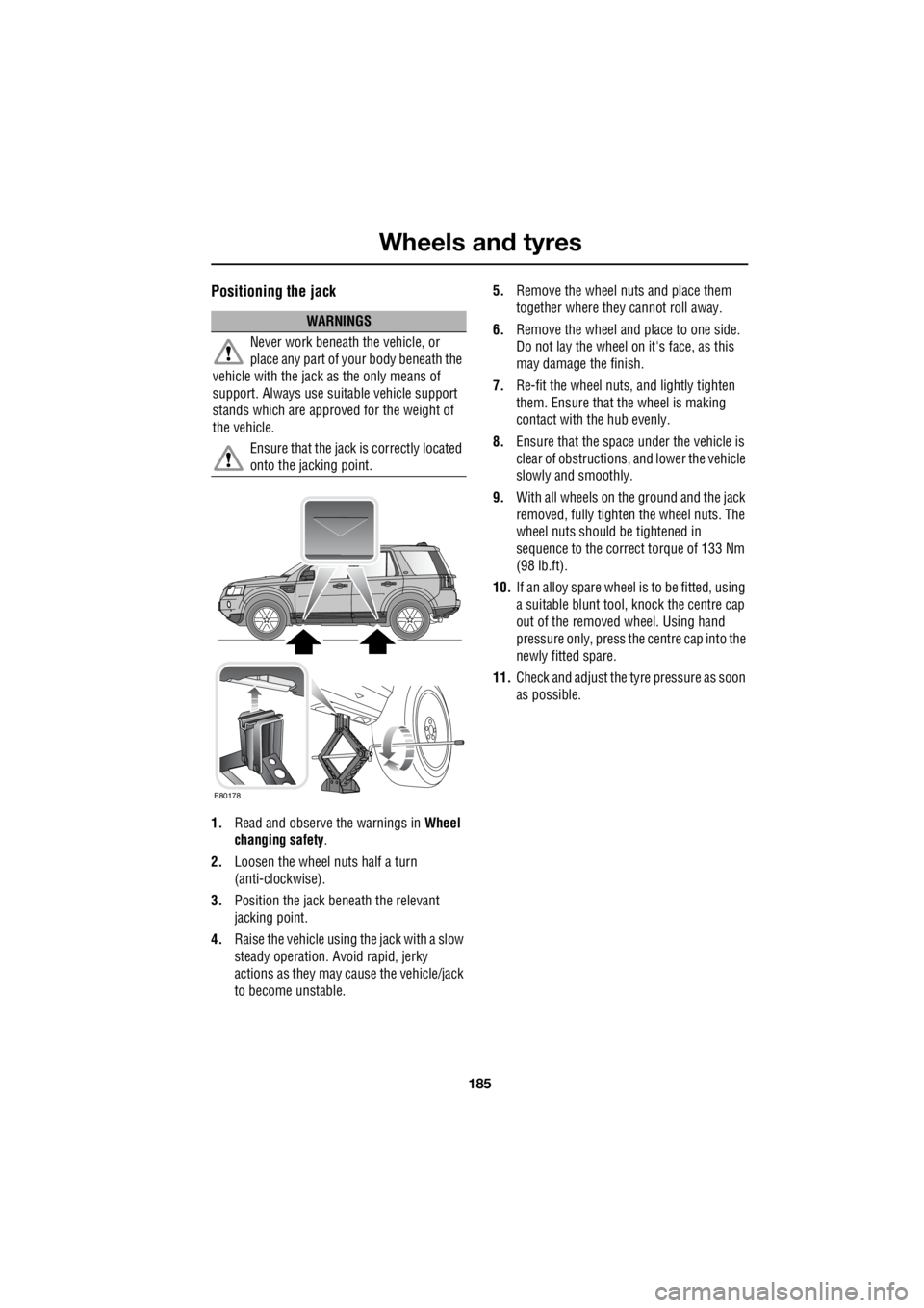
Positioning the jack
1. Read and observe the warnings in Wheel
changing safety .
2. Loosen the wheel nuts half a turn
(anti-clockwise).
3. Position the jack be neath the relevant
jacking point.
4. Raise the vehicle using the jack with a slow
steady operation. Avoid rapid, jerky
actions as they may cause the vehicle/jack
to become unstable. 5.
Remove the wheel nuts and place them
together where they cannot roll away.
6. Remove the wheel and place to one side.
Do not lay the wheel on it's face, as this
may damage the finish.
7. Re-fit the wheel nuts, and lightly tighten
them. Ensure that the wheel is making
contact with the hub evenly.
8. Ensure that the space under the vehicle is
clear of obstructions, and lower the vehicle
slowly and smoothly.
9. With all wheels on the ground and the jack
removed, fully tighte n the wheel nuts. The
wheel nuts should be tightened in
sequence to the correct torque of 133 Nm
(98 lb.ft).
10. If an alloy spare wheel is to be fitted, using
a suitable blunt tool, knock the centre cap
out of the removed wheel. Using hand
pressure only, press the centre cap into the
newly fitted spare.
11. Check and adjust the tyre pressure as soon
as possible.
WARNINGS
Never work beneath the vehicle, or
place any part of yo ur body beneath the
vehicle with the jack as the only means of
support. Always use su itable vehicle support
stands which are approved for the weight of
the vehicle.
Ensure that the jack is correctly located
onto the jacking point.
E80178
Page 2906 of 3229
Wheels and tyres
186
L
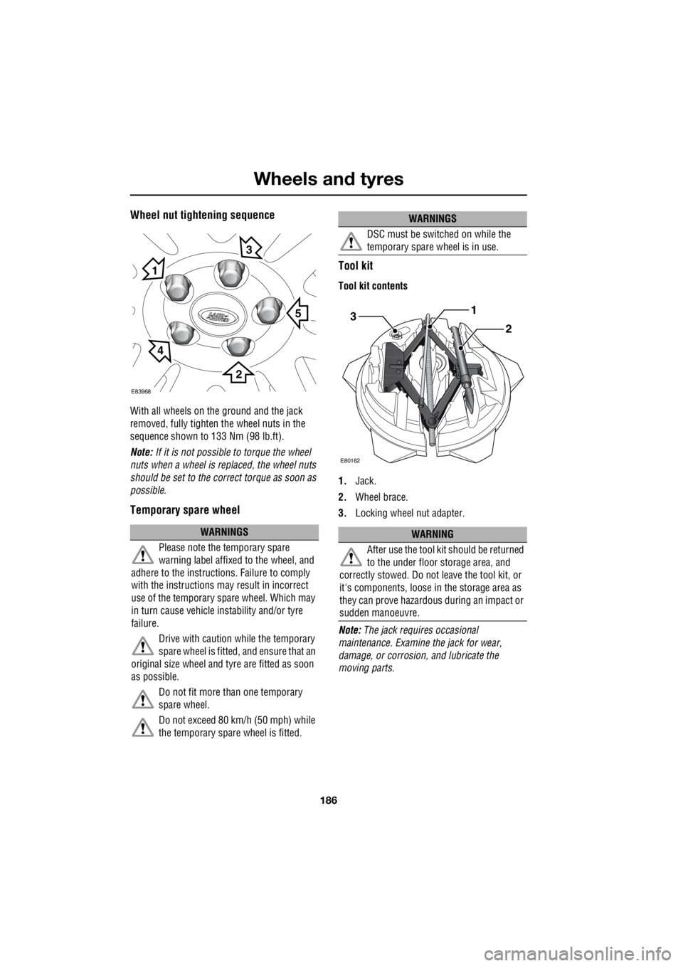
Wheel nut tightening sequence
With all wheels on the ground and the jack
removed, fully tighten the wheel nuts in the
sequence shown to 133 Nm (98 lb.ft).
Note: If it is not possible to torque the wheel
nuts when a wheel is replaced, the wheel nuts
should be set to the correct torque as soon as
possible.
Temporary spare wheel Tool kit
Tool kit contents
1.
Jack.
2. Wheel brace.
3. Locking wheel nut adapter.
Note: The jack requi res occasional
maintenance. Examine the jack for wear,
damage, or corrosion, and lubricate the
moving parts.
WARNINGS
Please note the temporary spare
warning label affixed to the wheel, and
adhere to the instructions. Failure to comply
with the instructions may result in incorrect
use of the temporary spare wheel. Which may
in turn cause vehicle instability and/or tyre
failure.
Drive with caution while the temporary
spare wheel is fitted, and ensure that an
original size wheel and tyre are fitted as soon
as possible.
Do not fit more than one temporary
spare wheel.
Do not exceed 80 km/h (50 mph) while
the temporary spare wheel is fitted.
E83968
5
1
3
2
4
DSC must be switched on while the
temporary spare wheel is in use.
WARNING
After use the tool kit should be returned
to the under floor storage area, and
correctly stowed. Do not leave the tool kit, or
it's components, loose in the storage area as
they can prove hazardous during an impact or
sudden manoeuvre.
WARNINGS
3
E80162
1
2
Page 2907 of 3229
187
Wheels and tyres
R
Locking wheel nuts
Locking wheel nuts can only be removed using
the special adapter provided in the tool kit.
Note: When the vehicle is first supplied the
adapter may be stored in the glove
compartment. It should be removed and stored
in the tool kit as soon as possible.
Note: A code number is stamped onto the
underside of the adapter. This number must be
recorded on the security card supplied with the
literature pack. If a replacement adapter is
required you will be asked to quote this
number. The security card must be kept safe,
but should not be kept with the vehicle.
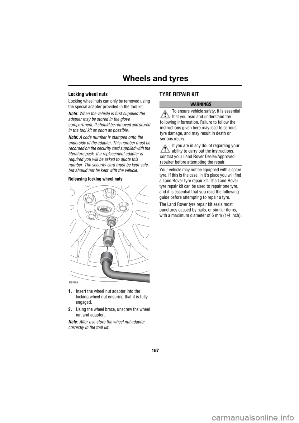
Releasing locking wheel nuts
1. Insert the wheel nut adapter into the
locking wheel nut ensuri ng that it is fully
engaged.
2. Using the wheel brace, unscrew the wheel
nut and adapter.
Note: After use store the wheel nut adapter
correctly in the tool kit.
TYRE REPAIR KIT
Your vehicle may not be equipped with a spare
tyre. If this is the case, in it's place you will find
a Land Rover tyre repair kit. The Land Rover
tyre repair kit can be us ed to repair one tyre,
and it is essential that you read the following
guide before attempting to repair a tyre.
The Land Rover tyre repair kit seals most
punctures caused by nails , or similar items,
with a maximum diameter of 6 mm (1/4 inch).
E83969
WARNINGS
To ensure vehicle safety, it is essential
that you read and understand the
following information. Failure to follow the
instructions given here may lead to serious
tyre damage, and may result in death or
serious injury.
If you are in any doubt regarding your
ability to carry out the instructions,
contact your Land Ro ver Dealer/Approved
repairer before attempting the repair.
Page 2910 of 3229

Wheels and tyres
190
L
Using the Land Rover tyre repair kit
Note: All vehicle drivers and occupants should
be made aware that a temporary repair has
been made to a tyre fitted to the vehicle. They
should also be made aware of the special
driving conditions im posed when using a
repaired tyre. Repair procedure
1. Open the tyre repair kit and peel off the
maximum speed label. Attach the label to
the facia in the driver's field of view. Take
care not to obstruct any of the instruments
or warning lights.
2. Uncoil the compressor power cable and
the inflation hose.
3. Unscrew the orange cap from the sealant
bottle receiver, and the sealant bottle cap.
4. Screw the sealant bottle into the receiver
(clockwise) until tight.
• Screwing the bottle onto the receiver will
pierce the bottle's se al. Do not unscrew
a full, or partly us ed bottle from the
receiver. Doing so will result in the
sealant leaking from the bottle.
5. Remove the valve cap from the damaged
tyre.
6. Remove the protective cap from the
inflation hose, and c onnect the inflation
hose to the tyre valve. Ensure that the hose
is screwed on firmly.
7. Ensure that the compressor switch is in
the off ( O) position.
8. Insert the power cable connector into an
auxiliary power socket. See AUXILIARY
POWER SOCKETS (page 110).
9. Unless the vehicle is in an enclosed or
poorly ventilated area , start the engine.
10. Set the compressor switch to the on ( l)
position.
11. Inflate the tyre to a minimum of 1.8 bar (26
lb/in²) and a maximum of 3.5 bar (51
lb/in²).
†
WARNINGS
Avoid skin contact with the sealant
which contains natu ral rubber latex.
Do not unscrew the sealant bottle from the
receiver until it is empty, as sealant will leak
out.
If the tyre inflation pressure does not
reach 1.8 bar (26 lb/in²) within seven
minutes, the tyre may have suffered excessive
damage. A temporary repair will not be
possible, and the vehicle should not be driven
until the tyre has been replaced.
CAUTIONS
Before attempting a tyre repair, ensure
that the vehicle is parked safely, as far
away from passing traffic as possible.
Ensure that the parki ng brake is applied,
and P is selected if an automatic
transmission is fitted.
Do not attempt to remove foreign objects
such as nails, screws, etc from the tyre.
Always run the engine when using the
compressor, unless the vehicle is in an
enclosed, or poorly ventilated space.
To prevent overheating do not operate
the compressor continuously for longer
than ten minutes.
Page 2911 of 3229

191
Wheels and tyres
R
12. During the inflation, switch the
compressor off briefly to check the tyre
pressure using the gauge mounted on the
compressor.
• It should not take longer than seven
minutes to inflate the tyre. If after seven
minutes the tyre ha s not reached the
minimum pressure, the tyre should not
be used.
13. Once the tyre has been inflated switch off
the compressor. If desired the engine may
be turned off after the compressor has
been turned off.
14. Remove the power connector from the
auxiliary power socket.
15. Remove the inflation hose from the tyre
valve by unscrewing it as quickly as
possible (anti-clockwise).
16. Replace the inflation hose protective cap,
and the tyre valve cap.
17. Do not remove the sealant bottle from the
receiver.
18. Ensure that the tyre repair kit (including
the bottle, and receiver caps) are placed
securely in the vehicle. You will need to
use the kit to check the tyre pressure after
3km (2 miles) so ensure they are easily
accessible.
19. Immediately drive the vehicle for 3 km (2
miles) to allow the sealant to coat the inner
surface of the tyre and form a seal at the
puncture.
†When pumping the sealant through the tyre
valve, the pressure may rise up to 6 bar (87
lb/in²). The pressure will drop again after
approximately 30 seconds.
Checking the tyre pressure after a repair
1. Drive the vehicle for 3 km (2 miles) then
stop in a safe place. Carry out a visual
examination of the tyres condition.
2. Remove the protective cap from the
inflation hose.
3. Screw the inflation hos e connector firmly
onto the tyre valve.
4. Read the tyre pressure from the gauge.
5. If the pressure of the sealant filled tyre is
above 1.3 bar (19 lb/in²) adjust the
pressure to the correct value. See
TECHNICAL SPECIFICATIONS (page 194).
6. Ensure that the compressor switch is in
the off position ( O), and insert the power
cable connector into an auxiliary power
socket. See AUXILIARY POWER
SOCKETS (page 110).
7. If the vehicle is in a well ventilated area,
start the engine.
8. Switch on the compressor ( I), and inflate
the tyre to the correct pressure.
WARNINGS
When driving the vehicle, if you
experience vibr ations, abnormal
steering, or noises, re duce speed immediately.
Drive with extreme caution and reduced speed
to the first safe place to stop the vehicle.
Visually examine the tyre, and check it's
pressure. If there are any signs of damage or
deformity to the tyre, or the tyre pressure is
below 1.3 bar (19 lb/i n²) do not continue
driving.
Consult a tyre repair centre, or your
Land Rover Dealer/Authorised repairer
for advice concerning the replacement of a
tyre after using a tyre repair kit.
Page 2920 of 3229

Fuses
200
L
Fuse number Rating (Amps) Fuse co lour Circuits protected
F1 5 tan Rain sensor
F2 10 red SRS
F3 5 tan ABS
F4 5 tan Instrument pack - Accelerator pedal - Light
Switch Module
F5 - - -
F6 15 blue Audio unit
F7 7.5 brown Steering wheel controls
F8 5 tan Instrument pack
F9 15 blue Headlamp main beam
F10 15 blue Sunroof
F11 7.5 brown Reverse lights and interior mirror dip
F12 - - -
F13 15 blue Front fog lamps
F14 15 blue Screen wash
F15 - - -
F16 - - -
F17 7.5 brown Interior lighting
F18 - - -
F19 5 tan Electric seat adjustment
F20 15 blue Rear wiper
F21 5 tan Alarm
F22 20 yellow Fuel pump
F23 20 yellow Steering column lock
F24 - - -
F25 10 red Tailgate - Fuel filler flap
F26 5 tan Diagnostic socket and alarm
F27 5 tan Start button and climate control
F28 5 tan Brake lights
Page 2925 of 3229
205
Status after a collision
R
Status after a collisionDRIVING AFTER A COLLISION
Before starting or driving
If the vehicle has been involved in an accident
it should be checke d thoroughly before
attempting to start the engine or drive the
vehicle.
Check for :-
• Fuel leaks.
• Fluid leaks.
• Battery damage.
• Damage to wiring.
• Damage to lights.
• Damage to steering, suspension, wheels
or tyres.
• Sharp or protruding bodywork.
• Operation of doors and locks.
• Condition and operation of seat belts and
SRS components.
• Condition of chil d seats and their
mounting/attach ment points.
Note: This list is not exhaustive.
Resetting the fuel cut-off
The fuel system cut-off forms part of the Safety
and Restraint System (SRS) fitted to your
vehicle. Following an im pact, and depending on
the severity, the fuel pump may be switched
off.
1. Switch the ignition off, and wait for one
minute.
2. Turn the ignition on for 30 seconds.
3. Check the vehicle thoroughly for fuel leaks.
If a leak is detected switch the ignition off
immediately.
• The vehicle must not be started if a leak
is present. Seek qualified advice, and
have the vehicle recovered.
4. If no leaks are detected, start the vehicle.
When driving
When driving a vehicle which has been
involved in a collision use caution and pay extra
attention to the operation of the vehicle. If any
changes in vehicle operati on after the collision
are noted when compared to it's operation
before the collision, do not continue to drive
the vehicle. Stop the vehicle as soon as it is
safe to do so, and have the vehicle recovered.
Pay particular attent ion to changes in :-
• Steering.
• Braking.
• Unusual noises.
• Warning lights or messages displayed.
• Problems with electrical systems.
WARNING
If the vehicle is involved in a collision it
should be checked by a Land Rover
Dealer/Authorised repairer, or suitably
qualified persons before starting or driving.
WARNING
The fuel cut-off s hould never be reset
if you can smell fuel , or a leak can be
seen. Doing so can lead to a fire which
may cause personal injury or death.