2006 LAND ROVER FRELANDER 2 lock
[x] Cancel search: lockPage 2521 of 3229
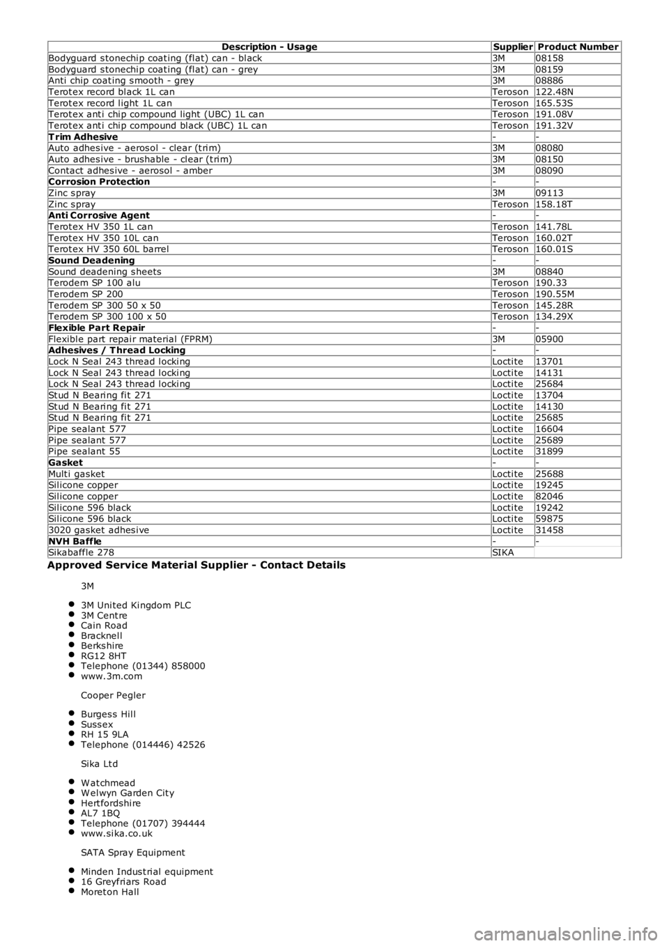
Description - UsageSupplierProduct Number
Bodyguard s tonechi p coat ing (fl at) can - bl ack3M08158
Bodyguard s tonechi p coat ing (fl at) can - grey3M08159Anti chip coat ing s mooth - grey3M08886
Terot ex record bl ack 1L canTeroson122.48N
Terot ex record l ight 1L canTeroson165.53STerot ex ant i chi p compound light (UBC) 1L canTeroson191.08V
Terot ex ant i chi p compound bl ack (UBC) 1L canTeroson191.32V
T rim Adhesive--Auto adhes ive - aeros ol - clear (t ri m)3M08080
Auto adhes ive - brushable - cl ear (t ri m)3M08150
Contact adhes ive - aerosol - amber3M08090Corrosion Protection--
Zinc s pray3M09113
Zinc s prayTeroson158.18TAnti Corrosive Agent--
Terot ex HV 350 1L canTeroson141.78L
Terot ex HV 350 10L canTeroson160.02TTerot ex HV 350 60L barrelTeroson160.01S
Sound Deadening--
Sound deadening s heets3M08840Terodem SP 100 aluTeroson190.33
Terodem SP 200Teroson190.55M
Terodem SP 300 50 x 50Teroson145.28RTerodem SP 300 100 x 50Teroson134.29X
Flexible Part Repair--
Flexibl e part repai r material (FPRM)3M05900Adhesives / T hread Locking--
Lock N Seal 243 thread l ocki ngLocti te13701
Lock N Seal 243 thread l ocki ngLocti te14131Lock N Seal 243 thread l ocki ngLocti te25684
St ud N Beari ng fi t 271Locti te13704
St ud N Beari ng fi t 271Locti te14130St ud N Beari ng fi t 271Locti te25685
Pipe sealant 577Locti te16604
Pipe sealant 577Locti te25689Pipe sealant 55Locti te31899
Gasket--
Mult i gasketLocti te25688Sil icone copperLocti te19245
Sil icone copperLocti te82046
Sil icone 596 blackLocti te19242Sil icone 596 blackLocti te59875
3020 gasket adhes i veLocti te31458
NVH Baffle--Sikabaffle 278SIKA
Approved Service Material Supplier - Contact Details
3M
3M Uni ted Ki ngdom PLC3M Cent reCain RoadBracknel lBerks hireRG12 8HTTelephone (01344) 858000www.3m.com
Cooper Pegler
Burges s Hil lSuss exRH 15 9LATelephone (014446) 42526
Sika Lt d
W at chmeadW el wyn Garden Cit yHert fordshi reAL7 1BQTelephone (01707) 394444www.si ka.co.uk
SATA Spray Equipment
Minden Indus t ri al equipment16 Greyfri ars RoadMoret on Hall
Page 2524 of 3229
Structural Adhesive
CAUTION: W hen separat ing a joint wi th metal t o met al adhes ive, it is important to avoi d dis t orti on. Heat graduall yunti l the bond weakens suffi ci ent ly to permit panel separat ion - do not apply excessi ve heat .
• NOTE: W hen s pot weldi ng through metal to metal adhesi ve, t ake part icul ar care t o adjus t the equipment s ett ing toensure a s uit able wel d.
Metal t o met al adhes ive i s appl ied t o cri ti cal joint areas duri ng factory as sembl y. The materi al us ed i s a hi gh temperat ure,heat cured, nit rile phenoli c which s erves t o bond two met al s urfaces and al so to seal t he joi nt agains t ingres s of dus t,mois t ure and fumes . Thi s mat erial i s not sui table for s ervice us e and, during repai r, s houl d be s ubs ti tut ed by an approveds truct ural adhes ive. For panel s pecific i nformati on and to identi fy t he areas of s t ructural adhesi ve appl icati on in repair,refer to the relevant s heet metal removal and ins t al lat ion procedure.
Expanding Foam Acoustic Seals
Expanding foam acoust ic s eals are us ed in various clos ed-s ect ions of t he body to i mprove vehicle refi nement . The s eal sare ins tall ed duri ng the vehicle body manufact ure and expand duri ng the pai nt process up t o t en t imes original s ize, thuslocking t hem i nt o pos it ion. They are l ocat ed s uch t hat they prevent nois e accentuat ion al ong a s ect ion and refl ect airborne nois e away from t he cabi n.
The s eal s have s pi lt funct ionalit y dependi ng on locati on. The s eals locat ed at t he bas e of t he body pill ars have a primaryfuncti on of prevent ing wat er ingres s when wadi ng. Their s econdary funct ion i s t o prevent noi s e and dust i ngres s.
The s eal around t he fuel fil ler has a pri mary functi on of prevent ing bot h fuel and water i ngress . W it h a s econdary funct ionof prevent ing noi se and dus t i ngress .
The remai ning s eals primary functi on is to prevent nois e accent uat ion al ong a s ect ion and refl ect ai r borne nois e awayfrom the cabin.
Another advantage of t he s eal s i s that t hey marginal ly i ncreas e t he overall s t iffness of t he body and it s s t ructuralperformance in cas e of a cras h.
The s eal s are manufact ured from an expandi bl e polymer.
Replacing Expanding Foam Acoustic Seals
As paint oven temperatures us ed i n a repai r works hop are s i gni fi cantl y l ower t han thos e t hat are us ed duri ng manufact ureof the vehicle, (the temperat ures are not suffi ci ent to expand the foam), a different proces s is required to repli cat e t hefoam in repair.
If a repair di st urbs t he expanding foam acoust ic seal it mus t be reins tat ed. If acces s all ows, (whether a new seal is fit t edor the origi nal i s reus ed), acous ti c foam s houl d be i nject ed aft er paint refinis hing. If access is not poss i bl e, or it is notpracti cal t o apply expandi ng foam due to the nat ure of t he repair, a s uit abl e flexible PU s eal er should be appl ied aroundt he seal and t he corres pondi ng body panel/s pri or to as s embly. In all cases t he appli cat ion of foam / s eal er should form as eal bet ween the expandi ng foam acous ti c s eal and any adjacent panelwork.
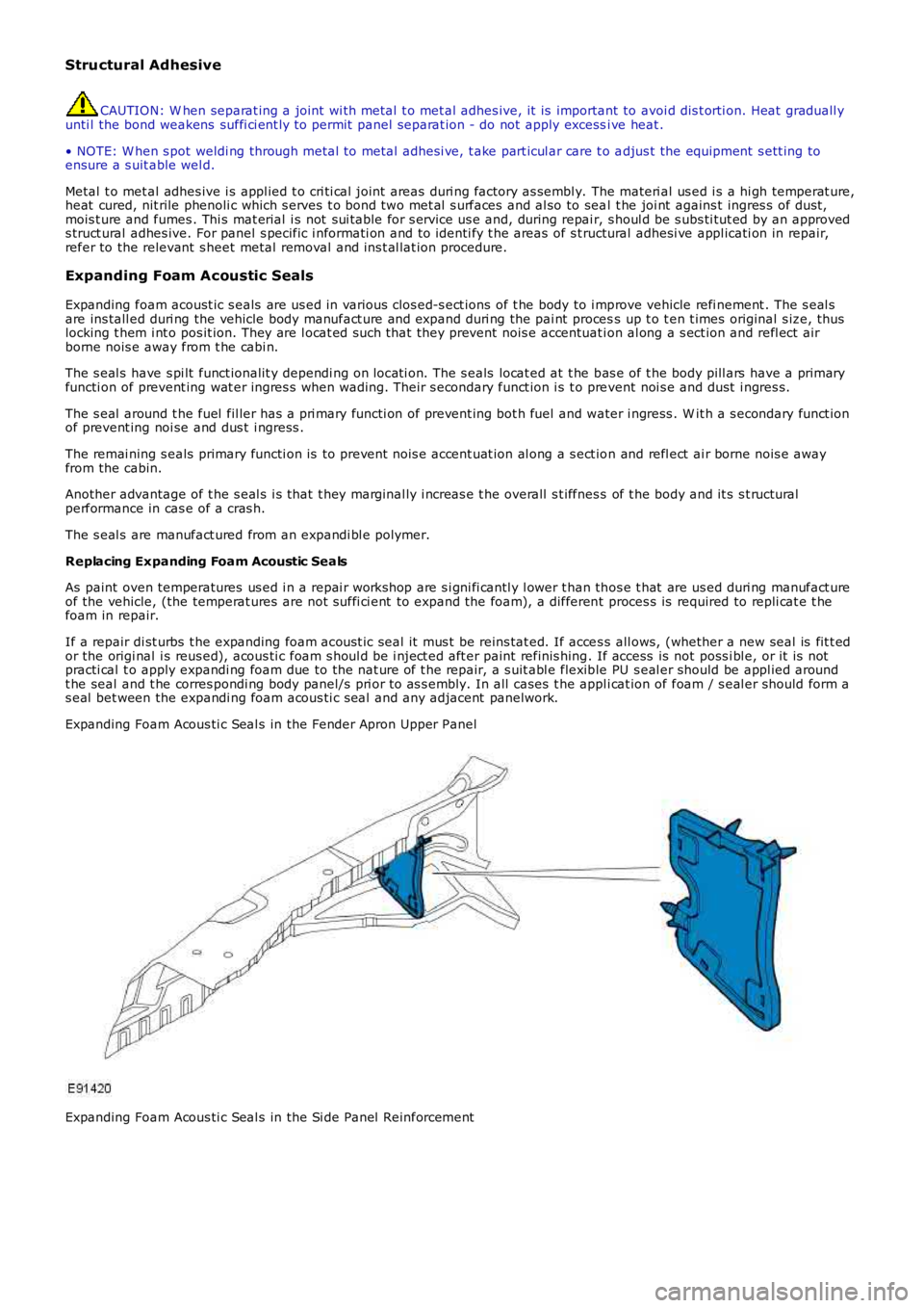
Expanding Foam Acous ti c Seal s in the Fender Apron Upper Panel
Expanding Foam Acous ti c Seal s in the Si de Panel Reinforcement
Page 2550 of 3229
Publi s hed: 11-May-2011
Front End Sheet Metal Repairs - Front Side Member
Removal and Inst all ati on
• NOTE: The front s ide member i s s erviced as a s eparate weld on panel. This procedure is to fit a long s ect ion cut from thes ervice panel, dis carding t he rear part .
• NOTE: The s ervice panel is not ful ly wel ded.
• NOTE: The s ect ion must be made at leas t 20mm forward of the l aser wel d.
1. The front s i de member is replaced in conjuncti on wit h:
Front bumper cover
Front bumper
Hood lat ch panel
Both front fenders
Front bumper mount ing
Front s ide member clos ing panel
Fender apron panel front reinforcement
Fender apron l ower panel
• NOTE: It is al so neces sary t o remove t he engine and s us pens ion as an as s embly.
2. For addit ional informati on rel at ing to this repair procedurepleas e s ee t he foll owing:For addi ti onal informat ion, refer t o: Body and Frame (501-26Body Repai rs - Vehi cl e Speci fic Informat ion and ToleranceChecks , Descripti on and Operat ion) /Standard W orks hop Practi ces (100-00 General Informat ion,Des cript ion and Operat ion).
3. Remove the front s ide member clos ing panel.For addi ti onal informat ion, refer t o: Front Side Member Cl os i ngPanel (501-27 Front End Sheet Met al Repai rs , Removal andIns t allat ion).
4. Remove the radi ator cool ing pack.For addi ti onal informat ion, refer t o: Radiator (303-03A Engi neCooling - I6 3.2L Petrol, Removal and Ins tall ati on).
5. Remove the engine and front s uspens ion as an as s embly.
6. Rel eas e and lay as ide t he brake pipe.
7. LH Side: Release the bat tery juncti on box and posi ti on asi de.
8. LH Side: Remove the ai r int ake pi pe.
9. LH Side: Release and lay as ide t he brake pi pe at the si demember.
10. LH Side: Remove the ant i-Lock brake s ys tem (ABS) Module.For addi ti onal informat ion, refer t o: Anti -Lock Brake Syst em(ABS) Module (206-09A Ant i-Lock Control, Removal andIns t allat ion).
11. RH Side: Remove the winds hi eld was her res ervoir.For addi ti onal informat ion, refer t o: W i nds hiel d W as herRes ervoi r (501-16 W i pers and W as hers , Removal andIns t allat ion).
12. RH Side: Remove the engi ne mount ing bracket .For addi ti onal informat ion, refer t o: Engi ne Mount RH (303-01BEngine - TD4 2.2L Dies el, Removal and Ins tall ati on).
13. RH Side: Remove the fender apron brake pipes .
14. RH Side: Remove the fender apron A/C pipe.
15. Rel eas e and l ay as ide t he ins ulat ing mat eri al at t hebulkhead.
16. Rel eas e and l ay as ide t he wiring harnes s .
Page 2723 of 3229

Contents
3
R
Quick start
QUICK START ................................................... 7
Filling station information
FILLING STATION INFORMATION................... 33
Introduction
SYMBOLS GLOSSARY .................................... 35
LABEL LOCATIONS ......................................... 35
HEALTH AND SAFETY ..................................... 36
DATA RECORDING.......................................... 37
DISABILITY MODIFICATIONS ......................... 37
PARTS AND ACCESSORIES ............................ 37
Keys and remote controls
USING THE KEY .............................................. 40
GENERAL INFORMATION ON RADIO
FREQUENCIES ................................................ 40
USING THE REMOTE CONTROL ..................... 41
Locks
LOCKING AND UNLOCKING ............................ 44
Alarm
ARMING THE ALARM ..................................... 45
DISARMING THE ALARM ............................... 46
Seats
SITTING IN THE CORRECT POSITION ............ 47
MANUAL SEATS ............................................. 48
ELECTRIC SEATS ............................................ 49
HEAD RESTRAINTS ........................................ 51
REAR SEATS................................................... 51
HEATED SEATS............................................... 53
Seat belts
PRINCIPLE OF OPERATION ............................ 54
SEAT BELT REMINDER ................................... 55
FASTENING THE SEAT BELTS ........................ 56
SEAT BELT HEIGHT ADJUSTMENT................. 56
USING SEAT BELTS DURI NG PREGNANCY .... 57
Supplementary restraints system
PRINCIPLE OF OPERATION ............................ 58
AIRBAG WARNING LAMP ............................... 61
DISABLING THE PASSENGER AIRBAG ........... 62
AIRBAG SERVICE INFORMATION ................... 63
Child safety
CHILD SEATS ................................................. 64
BOOSTER CUSHIONS ..................................... 66
ISOFIX ANCHOR POINTS................................ 67
CHILD SAFETY LOCKS ................................... 69
Steering wheel
ADJUSTING THE STEERING WHEEL .............. 70
AUDIO CONTROL ........................................... 70
Lighting
LIGHTING CONTROL ...................................... 72
FRONT FOG LAMPS........................................ 72
REAR FOG LAMPS.......................................... 73
ADJUSTING THE HEADLAMPS....................... 73
HEADLAMP LEVELLING ................................. 73
HAZARD WARNING FLASHERS...................... 74
ADAPTIVE FRONT LIGHTING SYSTEM (AFS) . 74
DIRECTION INDICATORS ............................... 75
INTERIOR LAMPS .......................................... 76
APPROACH LAMPS ........................................ 76
CHANGING A BULB ........................................ 77
BULB SPECIFICATION CHART ........................ 86
Wipers and washers
WINDSCREEN WIPERS .................................. 87
RAIN SENSOR ................................................ 87
WINDSCREEN WASHERS............................... 88
HEADLAMP WASHERS................................... 88
REAR WINDOW WIPER AND WASHERS ........ 89
ADJUSTING THE WINDSCREEN WASHER JETS .
89
CHECKING THE WIPER BLADES .................... 90
CHANGING THE WIPER BLADES.................... 90
Windows and mirrors
ELECTRIC WINDOWS ..................................... 93
EXTERIOR MIRRORS ..................................... 94
ELECTRIC EXTERIOR MIRRORS .................... 95
INTERIOR MIRROR ........................................ 96
Instruments
INSTRUMENT PANEL OVERVIEW .................. 97
Information displays
TRIP COMPUTER ........................................... 99
INFORMATION MESSAGES ............................ 99
Page 2724 of 3229

Contents
4
L
Climate control
AIR VENTS ................................................... 101
MANUAL CLIMATE CONTROL ...................... 102
AUTOMATIC CLIMATE CONTROL ................. 103
HEATED WINDOWS AND MIRRORS ............ 104
AUXILIARY HEATER ..................................... 104
ELECTRIC SUNROOF .................................... 105
Convenience features
SUN VISORS ................................................ 107
CLOCK .......................................................... 107
CIGAR LIGHTER ........................................... 109
ASHTRAY ..................................................... 109
AUXILIARY POWER SOCKETS ..................... 110
CUP HOLDERS ............................................. 111
STORAGE COMPARTMENTS ........................ 112
Starting the engine
GENERAL INFORMATION ............................. 113
STARTING A PETROL ENGINE ..................... 114
STARTING A DIESEL ENGINE ....................... 115
DIESEL PARTICULATE FILTER (DPF) ........... 116
Transmission
MANUAL TRANSMISSION ............................ 118
AUTOMATIC TRANSMISSION ...................... 118
TECHNICAL SPECIFICATIONS ...................... 122
Brakes
PRINCIPLE OF OPERATION .......................... 123
HINTS ON DRIVING WITH ABS .................... 123
PARKING BRAKE .......................................... 124
Parking aid
PRINCIPLE OF OPERATION .......................... 126
USING THE PARKING AID ............................ 127
Driving hints
GENERAL DRIVING POINTS ......................... 128
REDUCED ENGINE PERFORMANCE ............. 128
RUNNING-IN ................................................ 128
ECONOMICAL DRIVING ................................ 129
Cruise control
PRINCIPLE OF OPERATION .......................... 130
USING CRUISE CONTROL ............................ 130
Terrain response
PRINCIPLE OF OPERATION .......................... 132
USING TERRAIN RESPONSE ........................ 132
Hill descent control (HDC)
PRINCIPLE OF OPERATION .......................... 136
USING HDC ................................................... 137
Traction control
USING TRACTION CONTROL ........................ 139
Stability control
PRINCIPLE OF OPERATION .......................... 140
USING STABILITY CONTROL ........................ 141
Fuel and refuelling
SAFETY PRECAUTIONS................................. 142
FUEL QUALITY .............................................. 142
RUNNING OUT OF FUEL................................ 144
FUEL CUT-OFF............................................... 144
FUEL FILLER FLAP ........................................ 144
REFUELLING ................................................. 145
TECHNICAL SPECIFICATIONS ....................... 146
Load carrying
GENERAL INFORMATION.............................. 147
LUGGAGE ANCHOR POINTS ......................... 148
LUGGAGE COVERS ....................................... 149
Towing
TOWING A TRAILER...................................... 150
LEVELLING.................................................... 151
ESSENTIAL TOWING CHECKS ...................... 151
RECOMMENDED TOWING WEIGHTS ............ 152
TOW BAR ...................................................... 153
Vehicle care
CLEANING THE ALLOY WHEELS................... 154
CLEANING THE EXTERIOR ............................ 154
CLEANING THE INTERIOR ............................ 155
REPAIRING MINOR PAINT DAMAGE ............ 156
Maintenance
GENERAL INFORMATION.............................. 157
OPENING AND CLOSING THE BONNET......... 160
ENGINE COMPARTMENT OVERVIEW ........... 161
ENGINE OIL CHECK....................................... 162
Page 2727 of 3229
7
Quick start
R
Quick startQUICK START
Remote control
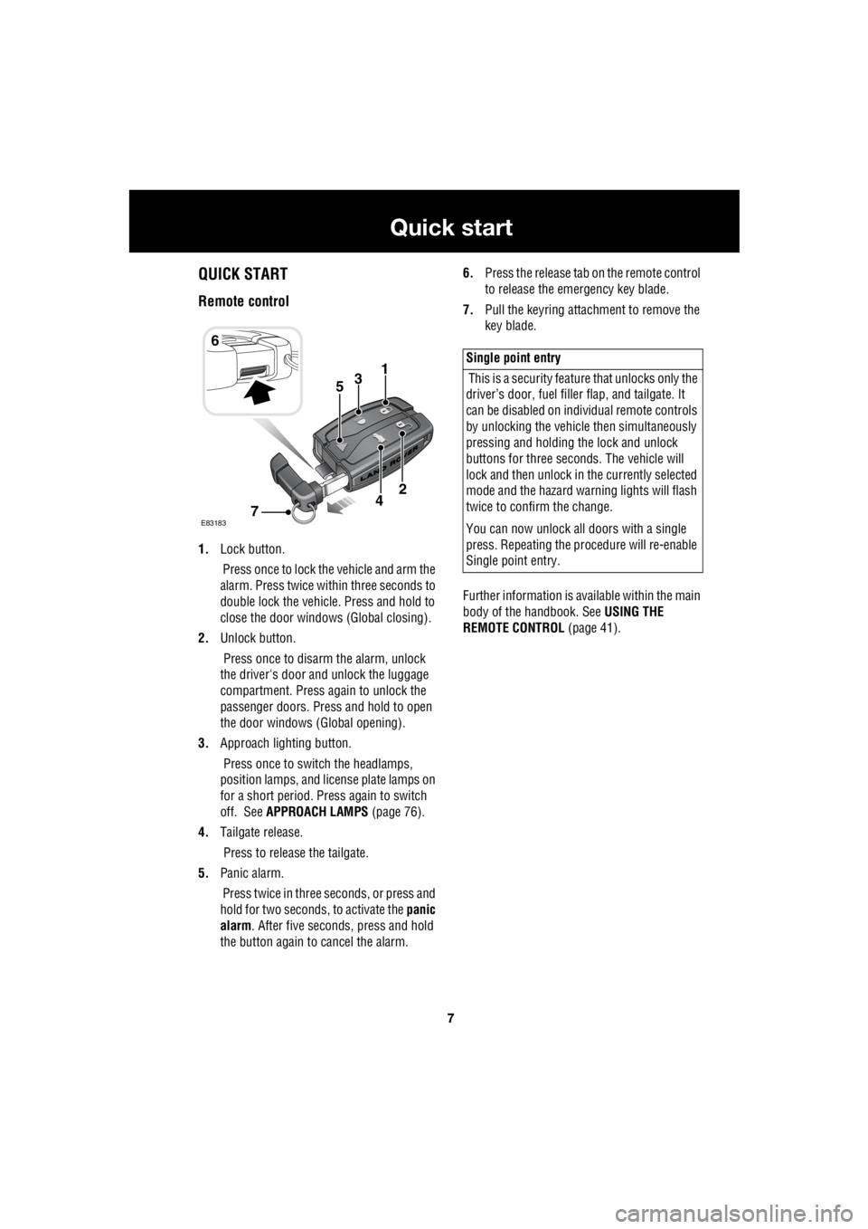
1. Lock button.
Press once to lock the vehicle and arm the
alarm. Press twice within three seconds to
double lock the vehicle. Press and hold to
close the door windows (Global closing).
2. Unlock button.
Press once to disarm the alarm, unlock
the driver's door and unlock the luggage
compartment. Press again to unlock the
passenger doors. Press and hold to open
the door windows (Global opening).
3. Approach lighting button.
Press once to switch the headlamps,
position lamps, and license plate lamps on
for a short period. Press again to switch
off. See APPROACH LAMPS (page 76).
4. Tailgate release.
Press to release the tailgate.
5. Panic alarm.
Press twice in three seconds, or press and
hold for two seconds, to activate the panic
alarm . After five seconds, press and hold
the button again to cancel the alarm. 6.
Press the release tab on the remote control
to release the emergency key blade.
7. Pull the keyring attachment to remove the
key blade.
Further information is available within the main
body of the handbook. See USING THE
REMOTE CONTROL (page 41).
6
31
E83183
2
74
5
Single point entry
This is a security feature that unlocks only the
driver’s door, fuel fille r flap, and tailgate. It
can be disabled on indi vidual remote controls
by unlocking the vehicle then simultaneously
pressing and holding th e lock and unlock
buttons for three sec onds. The vehicle will
lock and then unlock in the currently selected
mode and the hazard wa rning lights will flash
twice to confirm the change.
You can now unlock all doors with a single
press. Repeating the pr ocedure will re-enable
Single point entry.
Page 2729 of 3229
9
Quick start
R
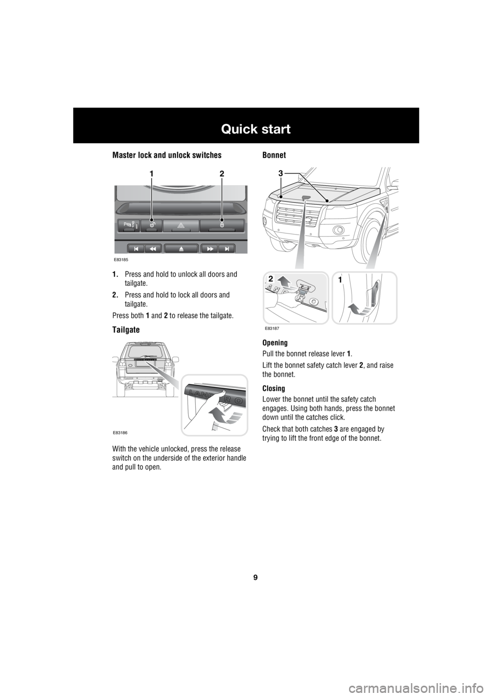
Master lock and unlock switches
1. Press and hold to unlock all doors and
tailgate.
2. Press and hold to lock all doors and
tailgate.
Press both 1 and 2 to release the tailgate.
Tailgate
With the vehicle unlocked, press the release
switch on the underside of the exterior handle
and pull to open.
Bonnet
Opening
Pull the bonnet release lever 1.
Lift the bonnet safety catch lever 2, and raise
the bonnet.
Closing
Lower the bonnet until the safety catch
engages. Using both hands, press the bonnet
down until the catches click.
Check that both catches 3 are engaged by
trying to lift the front edge of the bonnet.
12
E83185
E83186
12
3
E83187
Page 2731 of 3229
11
Quick start
R
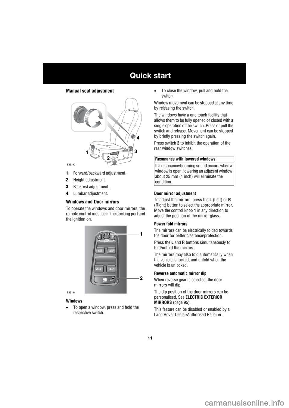
Manual seat adjustment
1. Forward/backward adjustment.
2. Height adjustment.
3. Backrest adjustment.
4. Lumbar adjustment.
Windows and Door mirrors
To operate the windows and door mirrors, the
remote control must be in the docking port and
the ignition on.
Windows
• To open a window, press and hold the
respective switch. •
To close the window, pull and hold the
switch.
Window movement can be stopped at any time
by releasing the switch.
The windows have a one touch facility that
allows them to be fully opened or closed with a
single operation of the switch. Press or pull the
switch and release. Mo vement can be stopped
by briefly pressing the switch again.
Press switch 2 to inhibit the operation of the
rear window switches.
Door mirror adjustment
To adjust the mirrors, press the L (Left) or R
(Right) button to select the appropriate mirror.
Move the control knob 1 in any direction to
adjust the position of the mirror glass.
Power fold mirrors
The mirrors can be electr ically folded towards
the door for better clearance/protection.
Press the L and R buttons simultaneously to
fold/unfold the mirrors.
The mirrors may also fold automatically when
the vehicle is locked, and unfold when the
vehicle is unlocked.
Reverse automatic mirror dip
When reverse gear is selected, the door
mirrors will dip.
The dip position of the door mirrors can be
personalised. See ELECTRIC EXTERIOR
MIRRORS (page 95).
This feature can be disabled or enabled by a
Land Rover Dealer/A uthorised Repairer.
3
2
1
E83190
4
1
2
E83191
Resonance with lowered windows
If a resonance/booming sound occurs when a
window is open, lowering an adjacent window
about 25 mm (1 inch) will eliminate the
condition.