Page 2339 of 3229
Publi s hed: 11-May-2011
Handles, Locks, Latches and Entry Systems - Exterior Front Door Handle
Removal and Inst all ati on
Removal
• NOTE: This procedure det ails removal and ins tall ati on of bot h t he LH and RH ext erior front door handles .
• NOTE: If the ext erior handl e i s to be removed i n conjunct ion wi th addi ti onal door internal i tems , t hen it i s recommendedt hat t he s crew cover and ext erior handle be releas ed from t he i ns i de of the door.
LH s i de: Remove t he pri vat e l ock.
Refer t o: Door Lock Cylinder (501-14 Handl es , Locks , Latches andEntry Syst ems , Removal and Inst all at ion).
1.
RH si de: Rel eas e t he 2 cl ips .2.
To remove the ext erior front door handle, wi thoutremoval of the door t ri m pad.3.
Page 2340 of 3229
To remove the ext erior front door handle, aft er removalof t he door t ri m pad and regul ator.4.
Installation
To i nst all , revers e t he removal procedure.1.
Us e a lengt h of cord to hol d the lock lever agai ns ts pri ng pres sure, while engaging t he outs i de handl e.2.
Page 2341 of 3229
Publi s hed: 11-May-2011
Handles, Locks, Latches and Entry Systems - Exterior Rear Door Handle
Removal and Inst all ati on
Removal
• NOTE: If the ext erior handl e i s to be removed i n conjunct ion wi th addi ti onal door internal i tems , t hen it i s recommendedt hat t he s crew cover and ext erior handle be releas ed from t he i ns i de of the door, after removal of the door t ri m pad,regulat or and motor.
Releas e t he 2 cli ps .1.
To remove the ext erior rear door handl e, wit houtremoval of the door t ri m pad.2.
To remove the ext erior rear door handl e, after removalof t he door t ri m pad and regul ator.3.
Installation
To i nst all , revers e t he removal procedure.1.
Page 2342 of 3229
Us e a lengt h of cord to hol d the lock lever agai ns ts pri ng pres sure, while engaging t he outs i de handl e.2.
Page 2343 of 3229
Publi s hed: 11-May-2011
Handles, Locks, Latches and Entry Systems - Door Lock Cylinder
Removal and Inst all ati on
Removal
• NOTE: This procedure is for removal and i nst all ati on of the door lock cyl inder only. The ignit ion l ock and door lockcyl inders are repl aced i n s ets .
1.
2. NOTE: Remove the s crew s uffi ci entl y, only to releas et he component.2.
Installation
To i nst all , revers e t he removal procedure.1.
Page 2369 of 3229

The rear glas s panel i s fixed in pos i ti on and bonded t o t he roof openi ng panel frame us i ng a PU adhes ive. The forwardglas s panel i s dri ven into pos i ti on by a pair of heli xed cables . The helixed cables are abl e t o pus h or pul l the forward glas spanel i nt o t he requi red pos it ion.
The roof openi ng panel al so cont ai ns 2 i nt egral, manuall y operat ed sunbli nds and 2 drai n hoses . The drai n hoses areconnected t o t he cent er of the frame above t he B pi ll ars . The drain hos es run through the cant rail s and down t he C pi llarst o all ow water coll ect ed in the frame to escape.
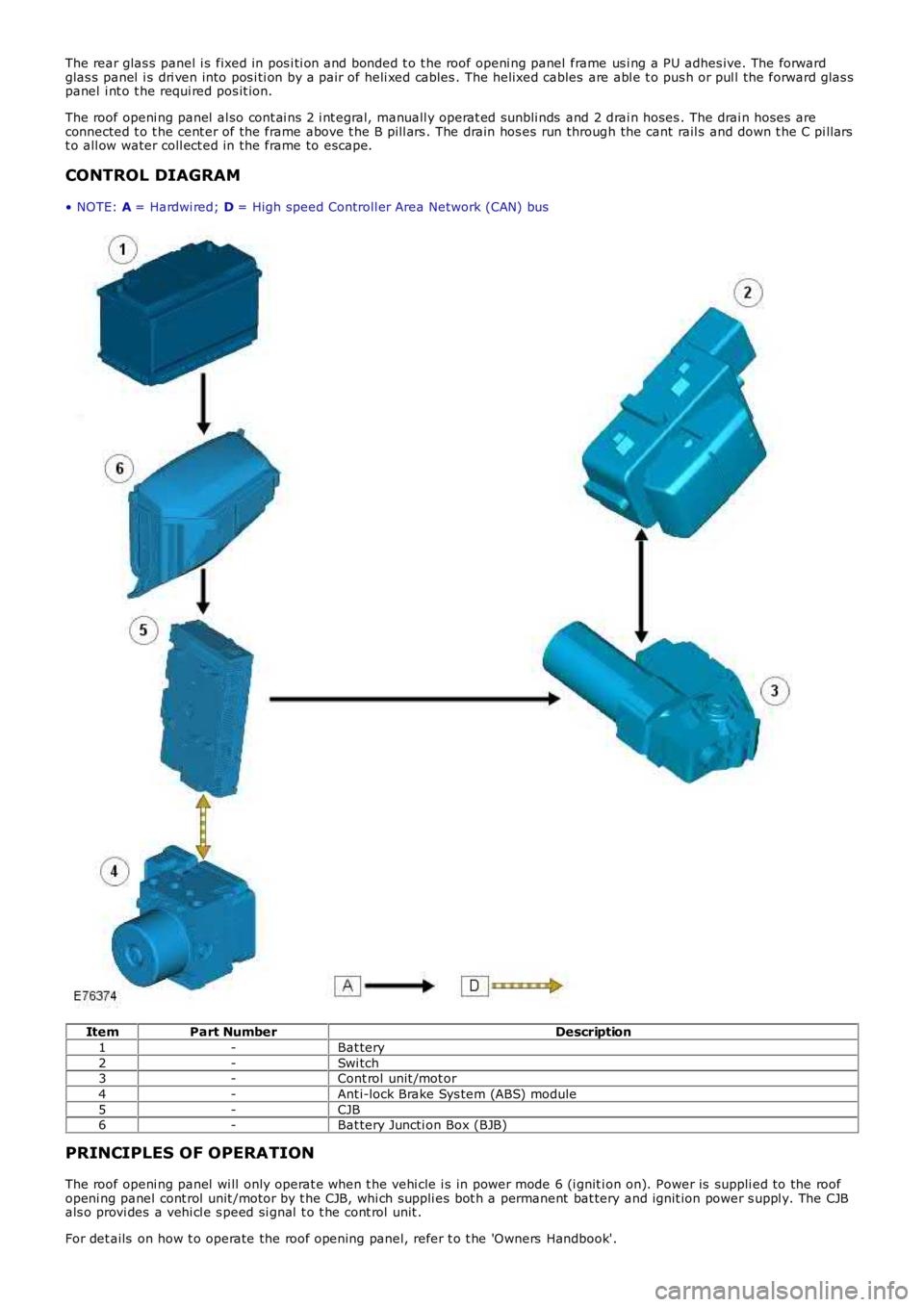
CONTROL DIAGRAM
• NOTE: A = Hardwi red; D = High speed Controll er Area Network (CAN) bus
ItemPart NumberDescription
1-Bat tery
2-Swi tch3-Cont rol unit /mot or
4-Ant i-lock Brake Sys tem (ABS) module
5-CJB6-Bat tery Juncti on Box (BJB)
PRINCIPLES OF OPERATION
The roof openi ng panel wi ll only operat e when t he vehi cle i s in power mode 6 (i gnit ion on). Power is suppli ed to the roofopeni ng panel cont rol unit /motor by t he CJB, whi ch suppli es bot h a permanent bat tery and ignit ion power s uppl y. The CJBals o provi des a vehi cl e s peed si gnal t o t he cont rol unit .
For det ails on how t o operate the roof opening panel, refer t o t he 'Owners Handbook'.
Page 2370 of 3229

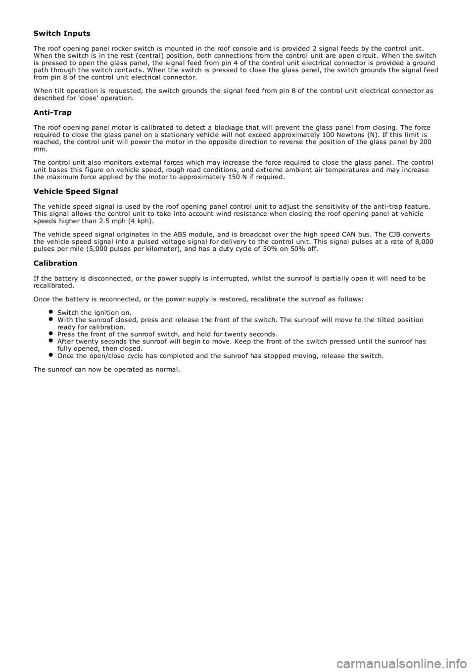
Switch Inputs
The roof openi ng panel rocker s wit ch is mount ed in the roof cons ol e and i s provided 2 si gnal feeds by t he control unit .W hen t he s wit ch is in t he res t (cent ral ) pos it ion, both connect ions from the cont rol uni t are open ci rcuit . W hen t he swit chis pres sed t o open t he glas s panel , the si gnal feed from pin 4 of t he cont rol unit electrical connect or is provi ded a groundpath through t he s wit ch cont act s . W hen t he s wit ch is pres s ed t o clos e t he glas s panel , the s wi tch grounds t he s ignal feedfrom pi n 8 of t he cont rol unit el ect ri cal connector.
W hen t il t operati on is reques t ed, t he s wit ch grounds the si gnal feed from pi n 8 of the cont rol unit electrical connect or asdescribed for 'cl ose' operati on.
Anti-Trap
The roof openi ng panel mot or is cali brat ed to det ect a blockage t hat wil l prevent t he glas s panel from cl osi ng. The forcerequired t o clos e t he glas s panel on a st ati onary vehi cl e wi ll not exceed approximately 100 Newt ons (N). If t his l imit isreached, t he cont rol unit wi ll power the motor in the oppos it e direct ion t o reverse the pos it ion of t he glas s panel by 200mm.
The cont rol unit al so monit ors external forces which may i ncrease the force requi red t o clos e t he glas s panel . The cont rolunit bas es this fi gure on vehicle speed, rough road condit ions, and ext reme ambi ent ai r temperatures and may increas et he maximum force appl ied by t he mot or t o approximat ely 150 N if requi red.
Vehicle Speed Signal
The vehi cl e s peed s ignal i s us ed by the roof openi ng panel cont rol unit t o adjus t t he s ens it ivi ty of t he anti -t rap feature.This s ignal all ows the control uni t to take i nt o account wi nd res is t ance when clos ing the roof opening panel at vehicl es peeds hi gher t han 2.5 mph (4 kph).
The vehi cl e s peed s ignal originat es in t he ABS modul e, and i s broadcas t over the hi gh s peed CAN bus . The CJB convert st he vehi cl e s peed si gnal i nt o a pul sed vol tage s ignal for deli very t o the cont rol uni t. Thi s s ignal puls es at a rate of 8,000puls es per mil e (5,000 puls es per ki lomet er), and has a dut y cycl e of 50% on 50% off.
Calibration
If the bat tery is di sconnect ed, or t he power s upply i s int errupt ed, whils t t he s unroof is part ial ly open i t wil l need t o berecali brated.
Once the bat tery is reconnected, or the power s uppl y is res tored, recal ibrat e t he s unroof as foll ows:
Swit ch the ignit ion on.W i th the s unroof clos ed, press and releas e t he front of t he s wit ch. The s unroof wi ll move t o t he ti lt ed posi ti onready for cali brat ion.Pres s t he front of t he s unroof s wit ch, and hold for twent y s econds .Aft er twent y s econds t he sunroof wi ll begin t o move. Keep the front of t he s wit ch pres sed unt il t he s unroof hasful ly opened, t hen clos ed.Once the open/cl os e cycle has complet ed and the sunroof has s topped moving, rel eas e the s wi tch.
The s unroof can now be operated as normal.
Page 2371 of 3229

Publis hed: 11-May-2011
Roof Opening Panel - Roof Opening PanelDia gnosis and Test ing
Principles of Operation
For a det ailed description of t he roof opening panel syst em, refer to t he relevant Description and Operat ion section in t he workshop ma nual.REFER t o: Roof Opening Panel (501-17 Roof Opening P anel, Des cript ion and Operation).
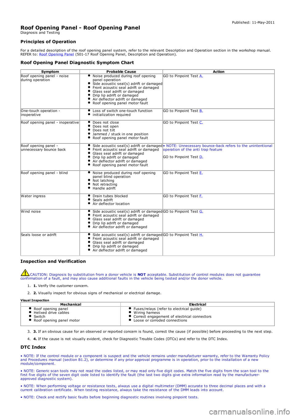
Roof Opening Panel Diagnostic Symptom Chart
SymptomProbable CauseActionRoof opening panel - noiseduring operationNoise produced during roof openingpanel operationSide acoust ic s eal(s) a drift or damagedFront acoust ic se al adrift or damagedGlass s eal adrift or dama gedDrip lip adrift or dama gedAir deflector adrift or damagedRoof opening panel mot or faul t
GO t o Pinpoint Tes t A.
One-touch operat ion -inoperativeLoss of switch one-touch funct ioninit ializ ation require dGO t o Pinpoint Tes t B.
Roof opening panel - inoperativeDoes not closeDoes not openDoes not t iltJammed / st uck i n one posit ionRoof opening panel mot or faul t
GO t o Pinpoint Tes t C.
Roof opening panel -unneces sary bounce backSide acoust ic s eal(s) a drift or damagedFront acoust ic se al adrift or damagedGlass s eal adrift or dama gedDrip lip adrift or dama gedAir deflector adrift or damagedRoof opening panel mot or faul t
• NOTE: Unnecess ary bounce -back refers t o the unintent ionalopera tion of t he ant i trap feat ure
GO t o Pinpoint Tes t D.
Roof opening panel - bl indNoise produced during roof openingpanel blind operat ionNot latchingNot ret ractingHandle adrift
GO t o Pinpoint Tes t E.
W at er ingressDrain t ubes blockedSea ls adriftAir deflector location
GO t o Pinpoint Tes t F.
W ind nois eSide acoust ic s eal(s) a drift or damagedFront acoust ic se al adrift or damagedGlass s eal adrift or dama gedDrip lip adrift or dama gedAir deflector adrift or damaged
GO t o Pinpoint Tes t G.
Se als loose or adriftSide acoust ic s eal(s) a drift or damagedFront acoust ic se al adrift or damagedGlass s eal adrift or dama gedDrip lip adrift or dama gedAir deflector adrift or damaged
GO t o Pinpoint Tes t H.
Inspection and Verification
CAUTION: Diagnos is by subs tit ut ion from a donor vehicle is NOT acce ptabl e. Subst itut ion of control modul es does not guarant eeconfirmat ion of a fault , and may also cause addit ional fault s in t he vehicle being test ed and/or the donor vehicle .
1. Verify t he cus tome r concern.1.
2. Visual ly inspect for obvi ous signs of me chanical or elect rical da mage.2.
Visual InspectionMechanicalElectricalRoof opening pane lHelixed drive cablesSwitchRoof opening pane l motor
Fus es/relays (refer to elect rical guide)W iring harnessCorrect engagement of electrical connect orsLoose or corroded connect ions
3. If a n obvious cause for an observed or report ed concern is found, correct the cause (if possi ble) before proceeding t o the ne xt s tep.3.
4. If t he cause is not vis ually evide nt, check for Diagnost ic Trouble Codes (DTCs ) and refer t o the DTC Index.4.
DTC Index
• NOTE: If t he control modul e or a component is sus pect and t he vehicle remains under ma nufact urer warrant y, refer t o t he Wa rrant y Policyand Procedure s manual (section B1.2), or determi ne if any prior a pproval programme is in operation, prior t o the insta llation of a newmodule/component .
• NOTE: Generic scan tools may not read t he codes list ed, or may re ad only five digit codes. Mat ch t he five digit s from t he scan tool t o t hefirs t five digits of t he seven digit code list ed t o ident ify t he fault (the last t wo digit s give ext ra informat ion read by t he manufacturer-approved diagnost ic syst em).
• NOTE: W hen performing volt age or resist ance tes ts , always use a digit al mult imet er (DMM) accurat e t o three decimal places and with acurrent calibrat ion certificate . W hen t est ing resist ance, always ta ke the res ist ance of t he DMM le ads int o account .
• NOTE: Check a nd re ct ify basic fa ults before beginning diagnosti c rout ines invol ving pinpoint t est s.