2006 LAND ROVER FRELANDER 2 brake
[x] Cancel search: brakePage 1863 of 3229
1
1
1
1
1
1
1
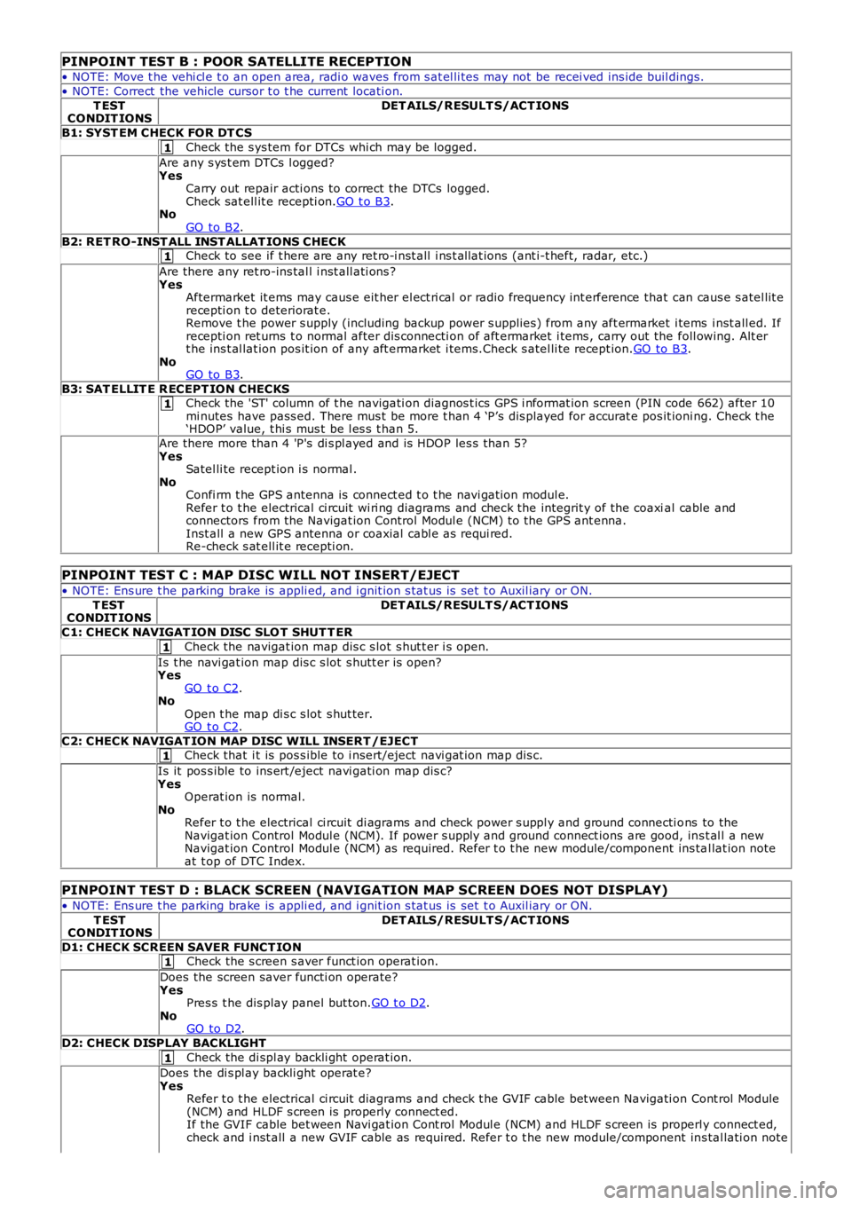
PINPOINT TEST B : POOR SATELLITE RECEPTION
• NOTE: Move t he vehi cl e t o an open area, radi o waves from s at el li tes may not be recei ved ins ide buil dings.
• NOTE: Correct the vehicle cursor t o t he current locati on.
T ESTCONDIT IONSDET AILS/RESULT S/ACT IONS
B1: SYST EM CHECK FOR DT CS
Check the s ys tem for DTCs whi ch may be logged.
Are any s ys t em DTCs l ogged?YesCarry out repair acti ons to correct the DTCs logged.Check sat ell it e recepti on.GO t o B3.NoGO to B2.
B2: RET RO-INST ALL INST ALLAT IONS CHECKCheck to see if t here are any ret ro-i nst all i ns t allat ions (ant i-t heft, radar, etc.)
Are there any ret ro-ins tal l i nst all ati ons ?YesAftermarket it ems may caus e eit her el ect ri cal or radio frequency int erference that can caus e s atel lit erecepti on t o deteriorat e.Remove t he power s upply (including backup power s upplies ) from any aft ermarket i tems i nst all ed. Ifrecepti on ret urns t o normal after dis connecti on of aft ermarket i tems , carry out the foll owing. Alt ert he ins t al lat ion pos it ion of any aft ermarket i tems.Check s atel li te recept ion.GO to B3.NoGO to B3.
B3: SAT ELLIT E R ECEPT ION CHECKSCheck the 'ST' column of t he navigati on diagnos t ics GPS i nformat ion screen (PIN code 662) after 10mi nutes have pass ed. There mus t be more t han 4 ‘P’s dis played for accurat e pos it ioning. Check t he‘HDOP’ value, t hi s mus t be l es s t han 5.
Are there more than 4 'P's di s pl ayed and is HDOP les s than 5?YesSatel li te recept ion i s normal .NoConfi rm t he GPS antenna is connect ed t o t he navi gat ion modul e.Refer t o t he electrical ci rcuit wi ri ng diagrams and check the integrit y of the coaxial cable andconnectors from the Navigat ion Control Modul e (NCM) to the GPS ant enna.Inst all a new GPS antenna or coaxial cabl e as requi red.Re-check s at ell it e recepti on.
PINPOINT TEST C : MAP DISC WILL NOT INSERT/EJECT
• NOTE: Ens ure t he parking brake is appli ed, and i gnit ion s tat us is set t o Auxil iary or ON.
T ESTCONDIT IONSDET AILS/RESULT S/ACT IONS
C1: CHECK NAVIGAT ION DISC SLO T SHUT T ER
Check the navigat ion map dis c s lot s hut t er i s open.
Is t he navi gat ion map dis c s lot s hutt er is open?YesGO t o C2.NoOpen t he map di s c s lot s hut ter.GO t o C2.
C2: CHECK NAVIGAT ION MAP DISC WILL INSERT /EJECTCheck that i t is pos s ible to i nsert/eject navi gat ion map dis c.
Is it pos s ible to ins ert /eject navi gati on map dis c?YesOperat ion is normal.NoRefer t o t he electrical ci rcuit di agrams and check power s uppl y and ground connecti ons to theNavigat ion Control Modul e (NCM). If power s upply and ground connect ions are good, ins t al l a newNavigat ion Control Modul e (NCM) as required. Refer t o t he new module/component ins tal lat ion noteat t op of DTC Index.
PINPOINT TEST D : BLACK SCREEN (NAVIGATION MAP SCREEN DOES NOT DISPLAY)
• NOTE: Ens ure t he parking brake is appli ed, and i gnit ion s tat us is set t o Auxil iary or ON.
T ESTCONDIT IONSDET AILS/RESULT S/ACT IONS
D1: CHECK SCREEN SAVER FUNCT IONCheck the s creen s aver funct ion operat ion.
Does the screen saver functi on operate?YesPres s t he dis play panel but ton.GO t o D2.NoGO to D2.
D2: CHECK DISPLAY BACKLIGHT
Check the di spl ay backli ght operat ion.
Does the di s pl ay backli ght operat e?YesRefer t o t he electrical ci rcuit diagrams and check t he GVIF cable bet ween Navigati on Cont rol Module(NCM) and HLDF s creen is properly connect ed.If the GVIF cable bet ween Navi gat ion Cont rol Modul e (NCM) and HLDF s creen is properly connect ed,check and i nst all a new GVIF cable as required. Refer t o t he new module/component ins tal lati on note
Page 1864 of 3229
1
1
1
1
1
1
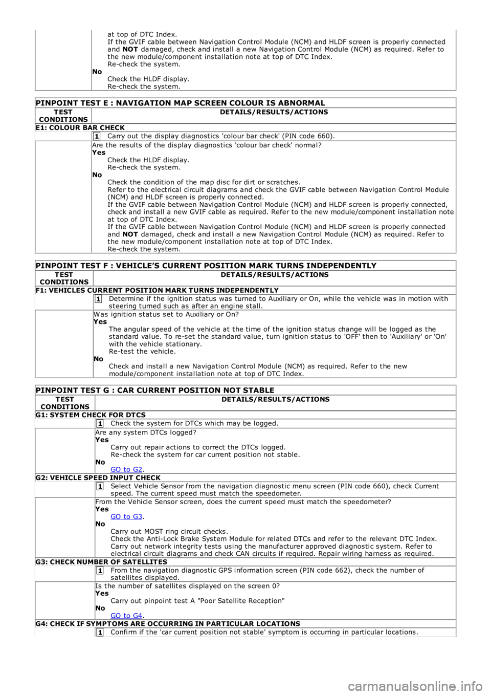
at t op of DTC Index.If the GVIF cable bet ween Navi gat ion Cont rol Modul e (NCM) and HLDF s creen is properly connect edand NOT damaged, check and i nst all a new Navi gat ion Cont rol Module (NCM) as required. Refer tot he new module/component ins tal lati on note at t op of DTC Index.Re-check the s ys tem.NoCheck the HLDF di spl ay.Re-check the s ys tem.
PINPOINT TEST E : NAVIGATION MAP SCREEN COLOUR IS ABNORMAL
T ESTCONDIT IONSDET AILS/RESULT S/ACT IONS
E1: COLOUR BAR CHECK
Carry out the di s pl ay diagnost ics 'colour bar check' (PIN code 660).
Are the res ul ts of t he dis play di agnos ti cs 'colour bar check' normal ?YesCheck the HLDF di spl ay.Re-check the s ys tem.NoCheck the condit ion of t he map dis c for di rt or s crat ches .Refer t o t he electrical ci rcuit diagrams and check t he GVIF cable bet ween Navigati on Cont rol Module(NCM) and HLDF s creen is properly connect ed.If the GVIF cable bet ween Navi gat ion Cont rol Modul e (NCM) and HLDF s creen is properly connect ed,check and i nst all a new GVIF cable as required. Refer t o t he new module/component ins tal lati on noteat t op of DTC Index.If the GVIF cable bet ween Navi gat ion Cont rol Modul e (NCM) and HLDF s creen is properly connect edand NOT damaged, check and i nst all a new Navi gat ion Cont rol Module (NCM) as required. Refer tot he new module/component ins tal lati on note at t op of DTC Index.Re-check the s ys tem.
PINPOINT TEST F : VEHICLE’S CURRENT POSITION MARK TURNS INDEPENDENTLY
T ESTCONDIT IONSDET AILS/RESULT S/ACT IONS
F1: VEHICLES CURRENT POSIT ION MARK T URNS INDEPENDENT LY
Det ermi ne if t he ignit ion st atus was turned to Auxil iary or On, whi le the vehicle was in moti on wit hs t eering t urned s uch as aft er an engi ne s tall .
W as ignit ion s t at us s et to Auxi liary or On?YesThe angular s peed of t he vehi cl e at t he ti me of t he igni ti on st atus change wil l be logged as t hes t andard val ue. To re-s et t he s tandard value, t urn i gni ti on s tat us to 'OFF' t hen t o 'Auxil iary' or 'On'wi th the vehicle st ati onary.Re-tes t the vehicle.NoCheck and ins tal l a new Navigati on Cont rol Module (NCM) as requi red. Refer t o t he newmodule/component ins tal lati on note at top of DTC Index.
PINPOINT TEST G : CAR CURRENT POSITION NOT STABLE
T ESTCONDIT IONSDET AILS/RESULT S/ACT IONS
G1: SYST EM CHECK FOR DT CS
Check the sys tem for DTCs whi ch may be l ogged.
Are any s ys t em DTCs l ogged?YesCarry out repair act ions to correct the DTCs logged.Re-check the sys tem for car current pos it ion not s table.NoGO to G2.
G2: VEHICLE SPEED INPUT CHECK
Select Vehicle Sens or from t he navi gat ion di agnos ti c menu s creen (PIN code 660), check Currents peed. The current speed mus t mat ch the speedometer.
From t he Vehi cl e Sensor s creen, does t he current s peed mus t mat ch the s peedomet er?YesGO to G3.NoCarry out MOST ring ci rcuit checks .Check the Ant i-Lock Brake Sys t em Module for rel at ed DTCs and refer to the relevant DTC Index.Carry out network int egrit y t est s us ing t he manufacturer approved di agnos ti c s ys t em. Refer toel ect ri cal circuit di agrams and check CAN circuit s i f required. Repair wi ring harness as required.
G3: CHECK NUMBER OF SAT ELLIT ES
From t he navi gat ion di agnos ti c GPS i nformat ion screen (PIN code 662), check t he number ofs atel li tes dis played.
Is t he number of s atel lit es dis played on t he s creen 0?YesCarry out pinpoint t est A "Poor Satell it e Recept ion"NoGO to G4.G4: CHECK IF SYMPT OMS ARE OCCURRING IN PART ICULAR LOCAT IO NS
Confi rm if t he 'car current pos it ion not s table' s ymptom is occurring i n part icular locati ons .
Page 1893 of 3229
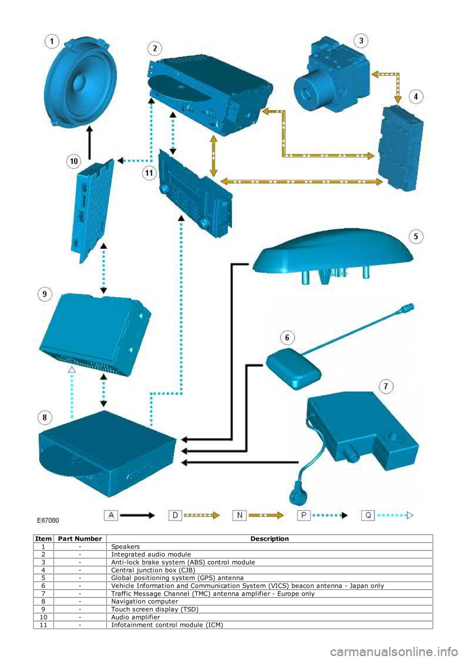
ItemPart NumberDescription
1-Speakers2-Int egrated audio modul e
3-Ant i-lock brake s ys tem (ABS) cont rol module
4-Cent ral juncti on box (CJB)5-Global pos it ioning s ys tem (GPS) antenna
6-Vehi cl e Informat ion and Communi cat ion Sys tem (VICS) beacon antenna - Japan onl y
7-Traffic Mes s age Channel (TMC) antenna ampl ifier - Europe only8-Navi gat ion computer
9-Touch s creen dis play (TSD)
10-Audi o ampli fi er11-Infot ainment cont rol module (ICM)
Page 1920 of 3229
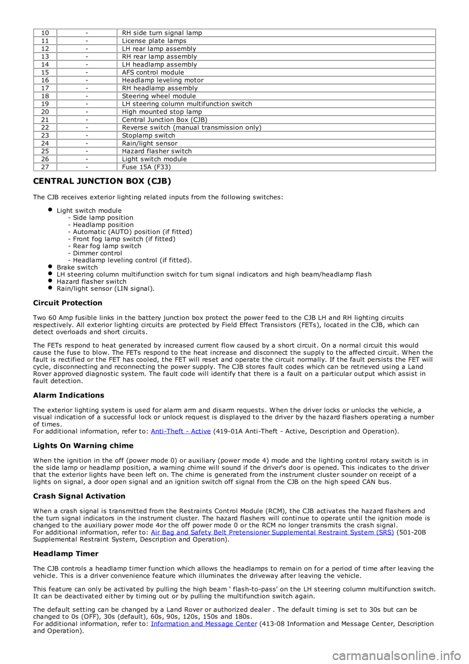
10-RH s i de turn s ignal lamp
11-Licens e pl ate lamps
12-LH rear l amp as s embl y13-RH rear lamp as s embly
14-LH headlamp as s embly
15-AFS cont rol module16-Headl amp l evel ing mot or
17-RH headlamp as s embly
18-Steering wheel modul e19-LH s t eering column mult ifunct ion s wit ch
20-High mount ed s top lamp
21-Central Junct ion Box (CJB)22-Revers e s wit ch (manual transmis si on only)
23-Stoplamp s wit ch
24-Rain/light s ensor25-Hazard flas her s wi tch
26-Light s wit ch modul e
27-Fuse 15A (F33)
CENTRAL JUNCTION BOX (CJB)
The CJB receives exteri or li ght ing relat ed inputs from t he fol lowing s wi tches:
Light s wit ch modul e- Side l amp pos it ion- Headlamp pos it ion- Automat ic (AUTO) posi ti on (if fi tt ed)- Front fog lamp swi tch (if fit ted)- Rear fog l amp s wit ch- Dimmer cont rol- Headlamp l evel ing control (if fit ted).Brake s wi tchLH s t eering column mult ifunct ion s wit ch for t urn si gnal i ndi cat ors and hi gh beam/headl amp flas hHazard flas her s wi tchRain/light s ensor (LIN si gnal ).
Circuit Protection
Two 60 Amp fus ibl e li nks in t he batt ery junct ion box protect the power feed to the CJB LH and RH li ght ing ci rcuit sres pect ively. All ext erior l ighti ng ci rcuit s are prot ect ed by Field Effect Trans is t ors (FETs ), l ocat ed in the CJB, which candetect overloads and s hort circuit s .
The FETs res pond to heat generated by increased current fl ow caus ed by a s hort ci rcuit . On a normal ci rcuit t his woul dcaus e t he fus e to bl ow. The FETs respond t o t he heat i ncrease and di s connect t he s uppl y t o t he affect ed ci rcuit . W hen t hefaul t is rect ified or t he FET has cool ed, t he FET wil l res et and operate t he circui t normall y. If t he faul t pers is ts the FET wi llcycle, di sconnect ing and reconnect ing t he power supply. The CJB s tores fault codes which can be ret rieved usi ng a LandRover approved diagnost ic sys tem. The fault code wil l identi fy t hat there is a fault on a part icular out put which as si s t infaul t det ect ion.
Alarm Indications
The exteri or li ght ing s ys tem is us ed for al arm arm and dis arm reques ts . W hen t he driver l ocks or unlocks the vehicle, avis ual i ndicat ion of a s uccess ful l ock or unlock reques t is di spl ayed t o t he dri ver by the hazard flas hers operat ing a numberof ti mes .For addit ional informat ion, refer t o: Anti -Theft - Act ive (419-01A Anti -Theft - Acti ve, Des cri pt ion and Operati on).
Lights On Warning chime
W hen t he i gni ti on in the off (power mode 0) or auxi liary (power mode 4) mode and the l ighti ng cont rol rotary swit ch is i nt he si de lamp or headlamp posi ti on, a warning chime wi ll s ound i f the driver's door is opened. This indicates t o t he dri vert hat t he exterior li ght s have been left on. The chime is generat ed from t he i ns t rument clus ter s ounder on receipt of ali ght s on s i gnal , a door open s ignal and an ignit ion swi tch off s ignal from t he CJB on the hi gh s peed CAN bus.
Crash Signal Activation
W hen a crash s ignal i s t rans mit ted from t he Rest rai nts Cont rol Modul e (RCM), t he CJB act ivat es the hazard flas hers andt he turn s ignal indicators in t he i ns t rument clus ter. The hazard fl ashers wil l continue to operate unt il t he ignit ion mode ischanged t o t he auxi liary power mode 4or the off power mode 0 or the RCM no longer trans mi ts the cras h si gnal .For addit ional informat ion, refer t o: Air Bag and Safet y Belt Pretens ioner Supplement al Res traint Syst em (SRS) (501-20BSuppl ement al Rest rai nt Sys tem, Des cri pti on and Operati on).
Headlamp Timer
The CJB cont rol s a headl amp t imer funct ion whi ch allows the headlamps t o remain on for a peri od of ti me after leaving t hevehi cl e. Thi s is a dri ver conveni ence feat ure which il lumi nat es t he dri veway after leaving t he vehicle.
This feat ure can onl y be acti vat ed by pulli ng t he high beam ' flas h-t o-pas s' on t he LH s t eering column mult ifunct ion s wi tch.It can be deacti vat ed eit her by ti ming out or by pull ing t he mul ti funct ion swi tch again.
The default s ett ing can be changed by a Land Rover or authorized deal er . The default t imi ng is s et t o 30s but can bechanged t o 0s (OFF), 30s (defaul t), 60s , 90s , 120s , 150s and 180s .For addit ional informat ion, refer t o: Informat ion and Mes s age Cent er (413-08 Informat ion and Mes s age Cent er, Des cript ionand Operat ion).
Page 1929 of 3229
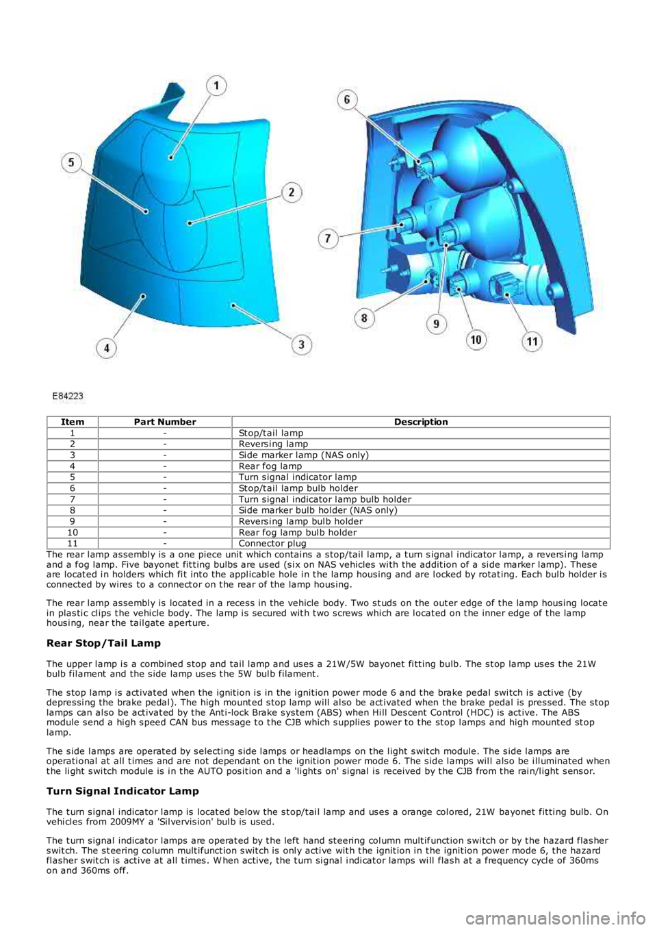
ItemPart NumberDescription
1-St op/t ail lamp2-Revers i ng lamp
3-Si de marker l amp (NAS only)
4-Rear fog lamp5-Turn s ignal indicator l amp
6-St op/t ail lamp bulb holder
7-Turn s ignal indicator l amp bulb holder8-Si de marker bulb hol der (NAS only)
9-Revers i ng lamp bul b holder
10-Rear fog lamp bul b holder11-Connector plug
The rear l amp as sembl y is a one piece unit which contai ns a s top/tail l amp, a t urn signal indicator l amp, a revers i ng lampand a fog lamp. Five bayonet fit t ing bulbs are us ed (s i x on NAS vehicles wi th the addit ion of a si de marker l amp). Theseare locat ed i n holders whi ch fi t int o the appl icabl e hole i n t he lamp hous ing and are l ocked by rotat ing. Each bulb hol der i sconnected by wires to a connect or on t he rear of the lamp hous ing.
The rear l amp as sembl y is locat ed in a reces s in the vehicle body. Two s t uds on the out er edge of t he lamp hous ing locat ein plas ti c cl ips t he vehi cle body. The lamp i s s ecured wit h t wo s crews whi ch are l ocat ed on t he inner edge of t he lamphous i ng, near the tail gat e apert ure.
Rear Stop/Tail Lamp
The upper l amp i s a combined s top and tail l amp and us es a 21W /5W bayonet fi tt ing bulb. The s t op lamp us es t he 21Wbulb fil ament and the s ide lamp us es t he 5W bul b filament .
The s top l amp i s act ivat ed when the ignit ion i s in the i gnit ion power mode 6 and t he brake pedal swi tch i s acti ve (bydepres si ng the brake pedal ). The high mount ed s top lamp will al so be act ivated when the brake pedal is pres sed. The s toplamps can al so be act ivat ed by the Ant i-lock Brake s ys tem (ABS) when Hi ll Des cent Control (HDC) is act ive. The ABSmodule s end a hi gh s peed CAN bus mes sage t o t he CJB which s upplies power t o t he st op l amps and high mount ed st oplamp.
The s ide l amps are operat ed by s electi ng s ide l amps or headlamps on the l ight s wit ch module. The s ide l amps areoperati onal at all t imes and are not dependant on t he ignit ion power mode 6. The s ide l amps wil l als o be i ll uminated whent he li ght s wi tch module is i n t he AUTO pos it ion and a 'li ght s on' si gnal i s received by t he CJB from t he rai n/l ight s ens or.
Turn Signal Indicator Lamp
The t urn s ignal indicator l amp is locat ed below the s t op/t ai l lamp and us es a orange col ored, 21W bayonet fit ti ng bulb. Onvehi cl es from 2009MY a 'Sil vervis ion' bul b is used.
The t urn s ignal indicator l amps are operat ed by t he left hand st eering col umn mult ifunct ion s wi tch or by t he hazard flas hers wit ch. The s t eering column mult ifunct ion s wit ch is onl y acti ve wit h t he ignit ion i n t he ignit ion power mode 6, t he hazardfl asher s wit ch is act ive at all t imes . W hen act ive, the t urn si gnal i ndi cat or lamps wi ll flas h at a frequency cycl e of 360mson and 360ms off.
Page 1930 of 3229
If a bulb fails , t he remai ning t urn s i gnal indi cat or l amp bulb on that s ide of t he vehicle flas hes at normal s peed. Theappl icable t urn si gnal i ndi cat or in t he i ns t rument clus ter wi ll fl ash at double s peed t o al ert t he driver t o t he bul b fai lure.
Reversing Lamp
The revers i ng lamp is l ocat ed adjacent t o t he turn s ignal lamp and us es a 21W bayonet fit ti ng bul b.
The revers i ng lamp is acti ve when the ignit ion i s in the i gnit ion power mode 6 and the CJB receives a revers e s el ect eds ignal on the medi um s peed Control ler Area Network (CAN) bus . The aut omati c t rans miss ion has a revers e s wit ch whichs ens es when reverse is s elect ed.
Rear Fog Lamp
The rear fog lamp is l ocat ed at the bot tom of the rear lamp and us es a 21W bayonet fit ti ng bul b.
The rear fog lamp is controlled by the l ight cont rol module. W hen the i gni ti on s wit ch is i n t he ignit ion power mode 6 andt he li ght control modul e is in t he s ide l amp or headl amp pos it ion, the rear fog l amp s wit ch on t he li ght control modul e canbe pres s ed t o act ivat e the rear fog l amps . A rear fog lamp warning i ndicat or is ill uminat ed in t he i ns t rument clus ter whent he rear fog lamps are act ive.
Side Marker Lamp (NAS only)
The s ide marker l amp i s located i n t he outer part of t he rear lamp, adjacent to rear fog lamp and us es a W 5W wedgefi tt ing bul b.
The s ide marker l amp bulb, whi ch is fit ted i n a hol der l ocat es in an aperture in the rear lamp hous ing and i s rot ated t o l ockin pos i ti on. The s ide marker lamp is acti ve at all ti mes when t he s ide l amps are select ed on us ing t he li ght controlmodule. The s ide marker l amps wi ll als o be i ll uminated when the l ight cont rol module rot ary s wit ch is in t he 'AUTO'posi ti on and a 'light s on' s i gnal is received by t he CJB from t he li ght sens or.
HAZARD FLASHERS
The hazard flas hers are cont roll ed by a non-l atching s wi tch i n the cent re of t he inst rument panel . The hazard fl as hersoperate at al l ti mes when s elected and are not dependant on the ignit ion power mode.
W hen t he hazard flas hers are s el ect ed on, all of the front , rear and s ide t urn s i gnal indi cat or l amps operate as previous lydescribed and both left and right t urn s ignal indicators in the ins trument cl us t er al s o fl ash. The hazard warning flas hersfl ash at a rat e of 360ms on and 360ms off. W hen the hazard flas hers are act ive, t hey override any reques t for t urn si gnallamp operati on.
If a trail er i s fit ted, the trailer t urn s i gnal lamps wil l flas h at t he s ame frequency as t he vehi cle i ndi cat ors . The t rail erwarni ng indicator i n t he ins trument cl ust er wil l al s o fl ash. If a t rail er bul b i s defect ive, t he trail er warning i ndi cat or wil l notfl ash.
The hazard flas hers can als o be acti vat ed by a crash si gnal from the Res t raint s Control modul e (RCM). This i s received byt he CJB which act ivat es the hazard flas hers . The hazard flas hers can be cancell ed by changing t he i gni ti on power mode tot he auxi liary power mode 4 or t he off power mode 0 or t he cras h mode i s cancelled by the res trai nts control modul e.
LICENSE PLATE LAMPS
Two l icens e pl ate l amps are fi tt ed in the t ail gat e handle, above t he l icens e pl ate in t he upper t ail gat e. Each l amp us es a5W caples s t ype bul b.
The lamps are s ecured in the upper li ft gat e handle wi th int egral cl ips . The lamps can be released from t he handl e us ing as mall , fl at bl ade screwdriver. The l icense pl ate lamps are act ive at al l ti mes when t he si de lamps or headlamps ares wit ched on.
HIGH MOUNTED STOP LAMP
The high mount ed s top l amp i s located i n t he li ft gat e. Acces s t o the lamp i s by removal of t he upper li ft gate interior t rimpanel . Aft er releas ing t he lamp ret aining cl ips , the l amp can be removed from outs ide the vehicle.
The lamp compris es a pl ast ic hous ing wi th a red col ored l ens . The lamp is i ll uminated by a s ingle 16W caples s type bulb.
The high mount ed s top l amp i s act ivat ed, along wit h the tail l amp s t op lamps , when the ignit ion i s in ignit ion power mode6 and t he brake pedal swi tch i s acti ve (by pres s ing the brake pedal).
The high mount ed s top l amp and t he s top l amps can als o be acti vat ed by t he ABS when Hi ll Des cent Control (HDC) isact ive. A s i gnal on t he high s peed CAN bus from the ABS modul e i s pass ed t o t he CJB which s uppl ies power to the st oplamps .
SIDE TURN SIGNAL LAMPS
The s ide t urn si gnal l amps are l ocat ed in the front fender air vents . On vehicles from 2009MY , t he s ide t urn si gnal l ampshave cl ear l enses and orange colored bulbs . The lamps are clipped i nt o an aperture in the vent panel and can be removedby s li di ng rearwards and releasi ng t he front edge of t he lamp from t he vent .
The s ide t urn si gnal l amps use a 5W caples s bulb which is locat ed i n a holder. The lamps have the same functi onal it y ast he front and rear turn s ignal i ndicat or lamps and are operat ed by the left hand s t eering column mult ifunct ion s wit ch or byt he hazard fl asher s wit ch. The s t eering column mult ifunct ion s wit ch is onl y acti ve wit h t he ignit ion i n t he ignit ion powermode 6, t he hazard fl asher s wit ch is act ive at all t imes , regardl ess of t he power mode. W hen act ive, t he s ide t urn s i gnallamps will flas h at a frequency cycle of 360ms on and 360ms off. If a s ide t urn si gnal l amp bulb fail s, t he t urn s i gnalindicat or l amps cont inue t o flas h at t he normal rat e.
Page 1932 of 3229
Publi s hed: 11-May-2011
Exterior Lighting - Headlamps
Diagnosi s and Tes ti ng
Principles of Operation
For a detail ed descripti on of the ext erior l ighti ng s ys t em, refer to t he Des cript ion and Operat ion secti on 417-00 - Ext eriorLighti ng of the workshop manual.
Safety Information
• W ARNINGS:
The Xenon Headl amp s ys tem generat es up t o 28,000 volt s . Make sure t hat t he headl amps are swit ched off beforeworki ng on the sys tem. Fai lure to foll ow t his i ns t ructi on may l ead to fat al it y.
The followi ng s afety precaut ions mus t be fol lowed when working on t he Xenon Headl amp Sys tem:
DO NOT att empt any procedures on t he Xenon Headlamps or circui ts when the sys tem is energi zed.Handl ing of t he xenon bul b mus t be performed us i ng sui table protect ive equipment, e.g. gl oves and goggles . Theglas s part of t he bulb mus t not be t ouched.Only operat e t he lamp in a mounted condit ion i n t he reflect or.All s afet y procedures and precaut ions mus t be foll owed to prevent pers onal injury.
CAUTION: Xenon bulbs mus t be dis pos ed of as hazardous was te.
There are ins t ructi ons on the correct procedures for Xenon Headlamp Sys t em repai rs in t he manual, refer to secti on 100-00- General Informat ion, Standard W orks hop Pract ices of t he works hop manual .
Inspection And Verification
CAUTION: Di agnos is by s ubs ti tut ion from a donor vehicle is NO T acceptabl e. Subs ti tut ion of cont rol modules doesnot guarant ee confirmat ion of a faul t, and may als o caus e addit ional fault s i n t he vehi cl e being t est ed and/or t he donorvehi cl e.
1. Verify t he cus t omer concern.
Note that int ermi tt ent fault report s may be due t o t he cycli ng operati on of the fi eld effect trans is t ors (FETs )
1.
2. Vis ually ins pect for obvious mechani cal or electrical fault s .2.
Visual Inspection Chart
MechanicalElectricalHeadlamp(s) condit ion and i ns t allat ionBulb(s) and ins tall ati onBulb hol der(s ) and i nst all at ionLight ing cont rol s wi tch and i ns t allat ionLeft -hand St eering Col umn Mult ifunct ion Swi tch andi ns t allat ion
Fus esRel aysW iring harnes sLoos e or corroded connector(s )Bat tery juncti on box (BJB)Cent ral juncti on box (CJB)Adapt ive Front Lighti ng Syst em (AFS)modul eHeadlamp Power modul esIns trument Clus ter (IPC)St eeri ng Angl e Sensor Module (SASM)Transmis si on Control Module (TCM)Engine Cont rol Module (ECM)Ant i-lock Brake Sys tem Modul eAi r Suspens ion Control Modul eLocal Int erconnect Net work (LIN) ci rcuit sCont roll er area network (CAN) ci rcuit s
3. If an obvious cause for an obs erved or report ed concern is found, correct t he caus e (if pos s ible) beforeproceeding t o t he next s t ep.3.
4. Us e the approved di agnos ti c s ys t em or a s can t ool t o ret rieve any diagnos t ic t rouble codes (DTCs ) before movingont o t he sympt om chart or DTC i ndex.
Becaus e t he DTCs are st ored i n more t han one modul e, a complete vehi cl e read i s recommendedMake s ure t hat all DTCs are cl eared fol lowing recti fi cat ion
4.
DTC Index
Adaptive Front Lighting System (AFS) Control Module
• NOTE: If the control modul e or a component i s s us pect and the vehicle remains under manufacturer warrant y, refer t o theW arranty Pol icy and Procedures manual (s ect ion B1.2), or determine i f any pri or approval programme is in operat ion, pri ort o the ins tall ati on of a new module/component.
Page 1959 of 3229
Publi s hed: 11-May-2011
Daytime Running Lamps (DRL) - Daytime Running Lamps (DRL)
Des cript ion and Operat ion
OVERVIEW
DRL us e t he ful l i ntens it y low beam headl amps which are permanentl y il lumi nat ed when t he vehi cl e i s being dri ven. DRLare us ed i n a number of market s and there are 2 s ys t ems t o cover t hes e markets .
For addit ional informat ion, refer t o: Ext eri or Li ght ing (417-01 Ext erior Light ing, Descri pti on and Operat ion).
DRL CANADIAN MARKET
DRL for t his market use full i ntens it y low beam headl amps. The s i de marker lamps , t ai l lamps and l icens e pl ate lamps wi llbe on, but ins trument cl us t er ill uminat ion wi ll be off. DRL are act ive when t he followi ng paramet ers are met:
PARK is not s elect ed on automat ic t rans mis s ion s elect or l everPower mode 6 (ignit ion on) detected by the auxil iary juncti on boxHandbrake is not applied.
• NOTE: If the rotary s wit ch on the light s wit ch module is moved t o t he headl amp posi ti on, DRL are deacti vat ed andnormal s ide l amp and headlamp funct ionali ty i s operat ional .
• NOTE: Adapt ive Front light ing Sys tem (AFS) (where fit ted) is non-funct ional when the DRL are act ive unles s t he rot arys wit ch on t he li ght s wi tch module is moved t o t he headl amp pos it ion.
• NOTE: W hen DRL are acti ve, t he headl amp flas h funct ion us ing t he left hand st eeri ng col umn mul ti funct ion swi tch willoperate normall y.
• NOTE: W hen DRL are acti ve, t he headl amp powerwas h funct ion i s non-funct ional , unles s the rotary s wit ch on t he li ghts wit ch module i s moved t o the headlamp pos i ti on.
The high beam headlamp functi on usi ng t he left hand s t eering column s talk swi tch will be deacti vat ed. W hen the sel ect orlever is i n t he PARK posi ti on on automat ic trans mi ss i on vehi cl es, DRL are t urned off. This i s to reduce bat t ery dis chargeduri ng long peri ods of engine idli ng in cold cl imat e condi ti ons. W hen the s elect or lever i s moved from t he PARK pos it ion,normal DRL funct ionalit y i s res t ored.
W hen t he handbrake is appli ed, DRL are t urned off t o reduce bat tery dis charge.
DRL DENMARK, HOLLAND, NORWAY, SWEDEN, FINLAND AND POLAND
• NOTE: DRL for Pol and is on vehicles from 2008MY .
DRL for t hese market s use full i ntens it y low beam headl amps. Si de lamps and l icense pl ate lamps wi ll be on, butins t rument clus ter il lumi nat ion will be off. DRL are acti ve when the foll owing paramet ers are met :
Power mode 6 (ignit ion on) detected by the auxil iary juncti on boxThe rot ary s wi tch on t he l ight s wit ch modul e i s in the off pos it ion.
• NOTE: W hen DRL are acti ve, t he headl amp flas h funct ion us ing t he left hand st eeri ng col umn mul ti funct ion swi tch willoperate normall y. The hi gh beam headlamp funct ion us ing the l eft hand s teeri ng column s t alk s wit ch wi ll be deact ivated.
• NOTE: W hen DRL are acti ve, t he headl amp powerwas h funct ion i s non-funct ional , unles s the rotary s wit ch on t he li ghts wit ch module i s moved t o the headlamp pos i ti on.
If the rotary s wit ch on the light s wit ch module i s moved t o t he s ide l amp or headl amp posi ti ons , DRL are deact ivated andnormal s ide l amp and headlamp funct ionali ty i s operat ional .