2006 LAND ROVER FRELANDER 2 brake
[x] Cancel search: brakePage 2709 of 3229
Publ is hed: 11-May-2011
Uni-Body, Subframe and Mounting System - Rear Subframe
Removal and Installation
General Equipment
P o we rt ra i n Ja ck
Removal
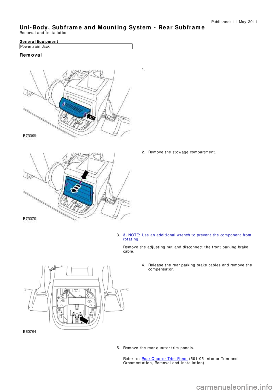
1.
Remove the stowage compartment. 2.
3. NOTE: Use an additional wrench to prevent the component from
ro t a t i ng .
Remove t he adjus t i ng nut and di s connect t he front parki ng brake
cabl e . 3.
Release the rear parking brake cables and remove the
compens at or. 4.
Remove the rear quarter trim panels.
Refer to: Rear Quarter Trim Panel
(501-05 Int eri or Tri m and
Ornament at i on, Removal and Ins t al lat i on). 5.
Page 2712 of 3229
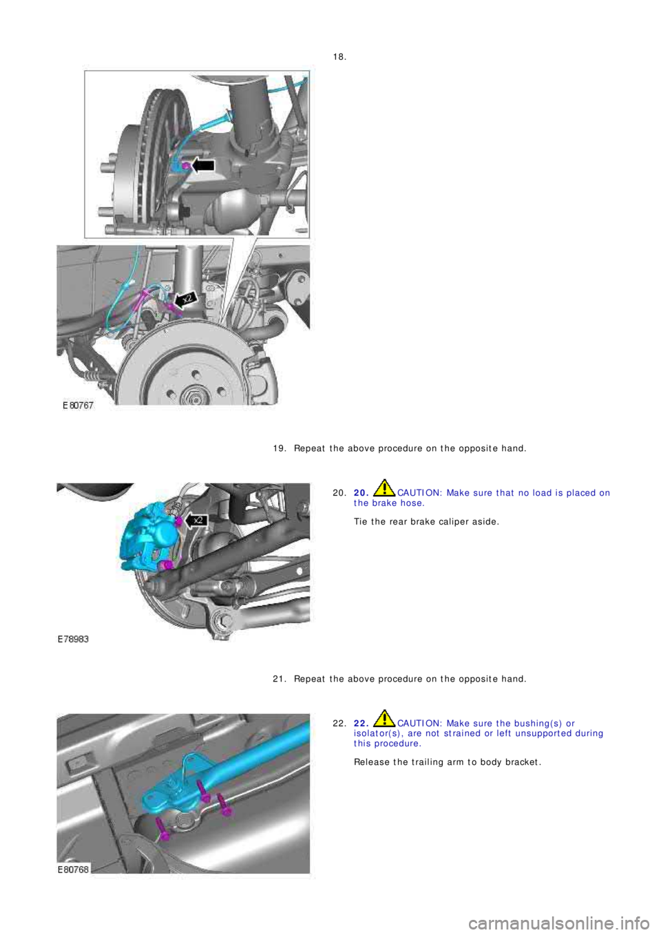
18.
Repeat the above procedure on the opposite hand. 19.
20. CAUTION: Make sure that no load is placed on
the brake hose.
Tie the rear brake caliper aside. 20.
Repeat the above procedure on the opposite hand. 21.
22. CAUTION: Make sure the bushing(s) or
isolator(s), are not strained or left unsupported during
this procedure.
Release the trailing arm to body bracket. 22.
Page 2715 of 3229
1. CAUTION: Make sure that new bolts are installed.
Clean the component mating faces.
With assistance, install the subframe.With assistance, align and secure the differential.Tighten the rear bolts.
Torque: 110 Nm
Tighten the front bolts.
Torque: 175 Nm
1.
2.
CAUTION: Make sure that new bolts are installed.
Align the suspension arms to the subframe and install the bolts, do
not fully tighten at this stage. 2.
Using the special tool, support the subframe. 3.
Connect the transmission breather lines. 4.
5. CAUTIONS:
Make sure that no components catch.
Make sure that new bolts are installed.
With assistance, position the subframe to the body and tighten the
bolts.
Torque: 175 Nm
5.
6.
CAUTION: Make sure that new bolts are installed.
Install the stabilizer clamp bolts, but do not tighten fully at this
stage. 6.
Connect the Active On-demand Coupling module electrical connector. 7.
Re mo ve t he p o we rt ra i n j a ck.
General Equi pment : P o w e rt ra i n Ja ck
8.
9.
CAUTION: Make sure that new bolts are installed.
Install the trailing arm to body brackets.
Torque: 110 Nm9.
10.
CAUTION: Make sure that the brake hose is not twisted
and is correctly located.
Clean the component mating faces.
Install the brake caliper anchor plate.
Torque: 110 Nm
Repeat the above procedure for the other side.
10.
Secure the wheel speed sensor and lead.
11.
Page 2716 of 3229
Torque: 5 NmSecure the lead in the clips.Repeat the above procedure for the other side.
LH side: Connect the ride height sensor electrical connector. 12.
Position and secure the rear shock absorbers.
Install both mass dampers.
Torque: 25 Nm
Repeat the above procedure for the other side.
13.
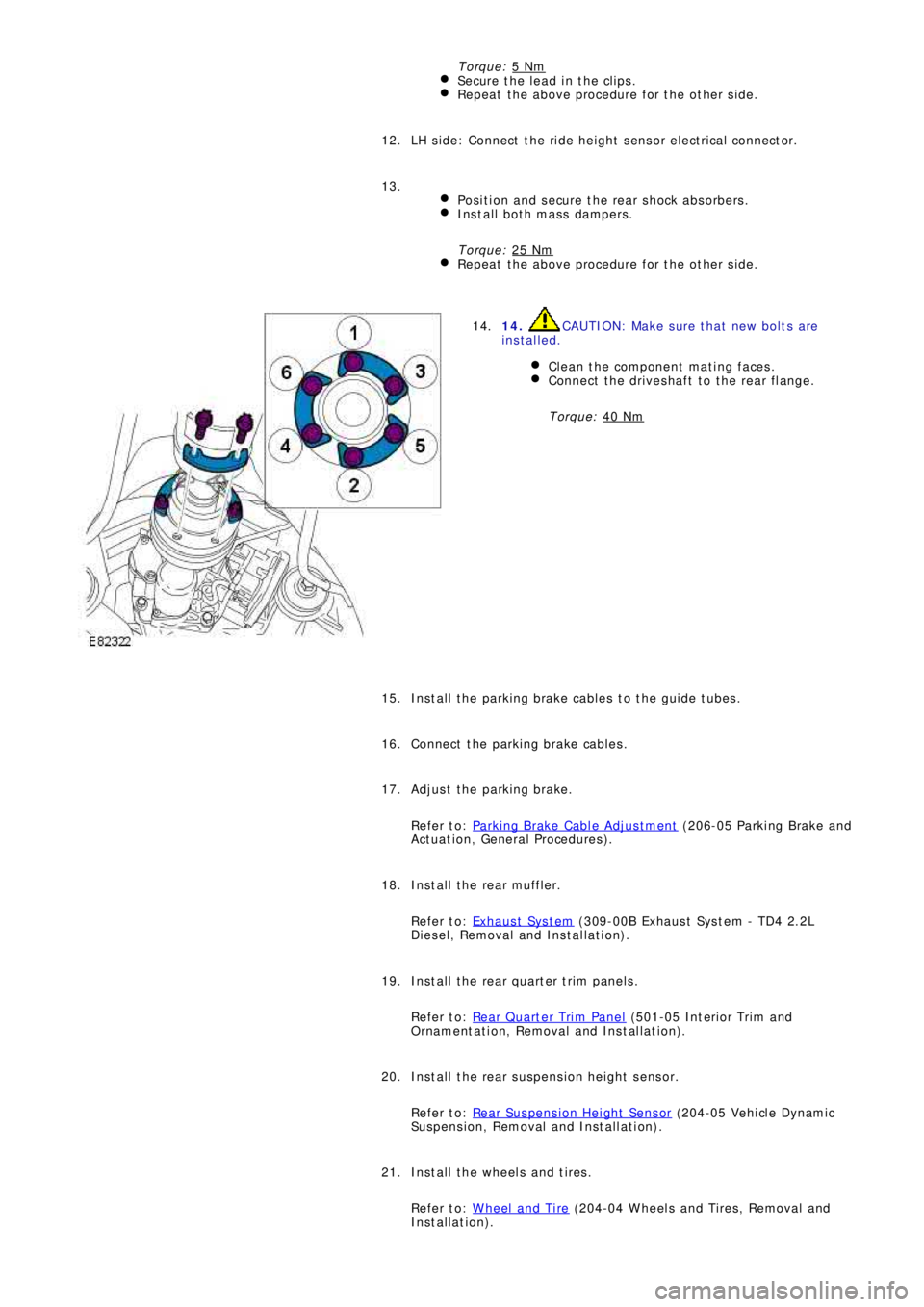
14. CAUTION: Make sure that new bolts are
installed.
Clean the component mating faces.
Connect the driveshaft to the rear flange.
Torque: 40 Nm
14.
Install the parking brake cables to the guide tubes. 15.
Connect the parking brake cables. 16.
Adjust the parking brake.
Refer to: Parking Brake Cable Adjustment
(206-05 Parki ng Brake and
Act uat i on, General Procedures ). 17.
Install the rear muffler.
Refer to: Exhaus t Sys t em
(309-00B Exhaus t Sys t em - TD4 2.2L
Diesel, Removal and Installation). 18.
Install the rear quarter trim panels.
Refer to: Rear Quarter Trim Panel
(501-05 Int eri or Tri m and
Ornament at i on, Removal and Ins t al lat i on). 19.
Install the rear suspension height sensor.
Refer to: Rear Suspension Height Sensor
(204-05 Vehi cl e Dynami c
Suspension, Removal and Installation). 20.
Install the wheels and tires.
Refer to: Wheel and Tire
(204-04 Wheels and Tires, Removal and
Installation). 21.
Page 2724 of 3229

Contents
4
L
Climate control
AIR VENTS ................................................... 101
MANUAL CLIMATE CONTROL ...................... 102
AUTOMATIC CLIMATE CONTROL ................. 103
HEATED WINDOWS AND MIRRORS ............ 104
AUXILIARY HEATER ..................................... 104
ELECTRIC SUNROOF .................................... 105
Convenience features
SUN VISORS ................................................ 107
CLOCK .......................................................... 107
CIGAR LIGHTER ........................................... 109
ASHTRAY ..................................................... 109
AUXILIARY POWER SOCKETS ..................... 110
CUP HOLDERS ............................................. 111
STORAGE COMPARTMENTS ........................ 112
Starting the engine
GENERAL INFORMATION ............................. 113
STARTING A PETROL ENGINE ..................... 114
STARTING A DIESEL ENGINE ....................... 115
DIESEL PARTICULATE FILTER (DPF) ........... 116
Transmission
MANUAL TRANSMISSION ............................ 118
AUTOMATIC TRANSMISSION ...................... 118
TECHNICAL SPECIFICATIONS ...................... 122
Brakes
PRINCIPLE OF OPERATION .......................... 123
HINTS ON DRIVING WITH ABS .................... 123
PARKING BRAKE .......................................... 124
Parking aid
PRINCIPLE OF OPERATION .......................... 126
USING THE PARKING AID ............................ 127
Driving hints
GENERAL DRIVING POINTS ......................... 128
REDUCED ENGINE PERFORMANCE ............. 128
RUNNING-IN ................................................ 128
ECONOMICAL DRIVING ................................ 129
Cruise control
PRINCIPLE OF OPERATION .......................... 130
USING CRUISE CONTROL ............................ 130
Terrain response
PRINCIPLE OF OPERATION .......................... 132
USING TERRAIN RESPONSE ........................ 132
Hill descent control (HDC)
PRINCIPLE OF OPERATION .......................... 136
USING HDC ................................................... 137
Traction control
USING TRACTION CONTROL ........................ 139
Stability control
PRINCIPLE OF OPERATION .......................... 140
USING STABILITY CONTROL ........................ 141
Fuel and refuelling
SAFETY PRECAUTIONS................................. 142
FUEL QUALITY .............................................. 142
RUNNING OUT OF FUEL................................ 144
FUEL CUT-OFF............................................... 144
FUEL FILLER FLAP ........................................ 144
REFUELLING ................................................. 145
TECHNICAL SPECIFICATIONS ....................... 146
Load carrying
GENERAL INFORMATION.............................. 147
LUGGAGE ANCHOR POINTS ......................... 148
LUGGAGE COVERS ....................................... 149
Towing
TOWING A TRAILER...................................... 150
LEVELLING.................................................... 151
ESSENTIAL TOWING CHECKS ...................... 151
RECOMMENDED TOWING WEIGHTS ............ 152
TOW BAR ...................................................... 153
Vehicle care
CLEANING THE ALLOY WHEELS................... 154
CLEANING THE EXTERIOR ............................ 154
CLEANING THE INTERIOR ............................ 155
REPAIRING MINOR PAINT DAMAGE ............ 156
Maintenance
GENERAL INFORMATION.............................. 157
OPENING AND CLOSING THE BONNET......... 160
ENGINE COMPARTMENT OVERVIEW ........... 161
ENGINE OIL CHECK....................................... 162
Page 2725 of 3229

Contents
5
R
ENGINE COOLANT CHECK ............................ 163
BRAKE AND CLUTCH FLUID CHECK ............. 165
POWER STEERING FLUID CHECK ................ 166
WASHER FLUID CHECK ................................ 167
TECHNICAL SPECIFICATIONS ...................... 169
Vehicle battery
BATTERY WARNING SYMBOLS ................... 171
BATTERY CARE ............................................ 171
USING BOOSTER CABLES ............................ 173
CHARGING THE VE HICLE BATTERY ............. 174
CHANGING THE VE HICLE BATTERY ............. 174
Wheels and tyres
GENERAL INFORMATION ............................. 176
TYRE CARE ................................................... 177
USING WINTER TYRES................................. 183
CHANGING A ROAD WHEEL ......................... 183
TYRE REPAIR KIT ......................................... 187
USING SNOW CHAINS.................................. 192
TYRE GLOSSARY.......................................... 193
TECHNICAL SPECIFICATIONS ...................... 194
Fuses
FUSE BOX LOCATIONS ................................. 195
CHANGING A FUSE ....................................... 195
FUSE SPECIFICATION CHART....................... 196
Emergency equipment
HAZARD WARNING FLASHERS .................... 204
WARNING TRIANGLE ................................... 204
Status after a collision
DRIVING AFTER A COLLISION...................... 205
INSPECTING SAFETY SYSTEM COMPONENTS ...
206
Vehicle recovery
TOWING POINTS .......................................... 207
LASHING POINTS ......................................... 208
TRANSPORTING THE VEHICLE..................... 208
TOWING THE VEHICLE ON FOUR WHEELS .. 208
Vehicle identification
VEHICLE IDENTIFICATION PLATE................. 210
VEHICLE IDENTIFI CATION NUMBER (VIN) ... 210
VEHICLE BUILD DATE PLATE ....................... 210
Technical specifications
ENGINE SPECIFICATIONS ............................ 211
WEIGHTS...................................................... 212
DIMENSIONS................................................ 213
Type approval
Declarations of conformity ........................... 215
Audio introduction
RADIO RECEPTION....................................... 218
Audio unit overview
AUDIO UNIT OVERVIEW............................... 219
Audio unit operation
ON OR OFF CONTROL .................................. 223
VOLUME CONTROL ...................................... 223
AUDIO CONTROL ......................................... 223
WAVEBAND BUTTON ................................... 224
AUTOSTORE CONTROL ................................ 225
STATION PRESET BUTTONS ........................ 226
TRAFFIC INFORMATION CONTROL .............. 226
Audio unit menus
RADIO DATA SYSTEM (RDS) ....................... 228
REGIONAL MODE (REG) .............................. 228
ENHANCED OTHER NETWORK (RDS-EON).. 229
ALTERNATIVE FREQUENCIES ...................... 229
NEWS BROADCASTS ................................... 230
PRIORITY PROGRAMME TYPE (PTY) .......... 231
RESETTING THE AUDIO UNIT ...................... 233
Digital audio broadcasting
GENERAL INFORMATION ............................. 234
AUDIO CONTROLS ....................................... 235
DISPLAY OPTIONS ....................................... 236
CHANNEL AUTOMATIC TUNING................... 236
CHANNEL OPTIONS ..................................... 236
PRESET BUTTONS ....................................... 238
SETTINGS..................................................... 240
Compact disc player
LOADING COMPACT DISCS ......................... 245
EJECTING COMPACT DISCS ........................ 246
EJECTING MULTIPLE CO MPACT DISCS....... 246
COMPACT DISC SELECTION ........................ 246
COMPACT DISC PLAYBACK ......................... 246
Page 2728 of 3229
8
Quick start
L
Engine starting
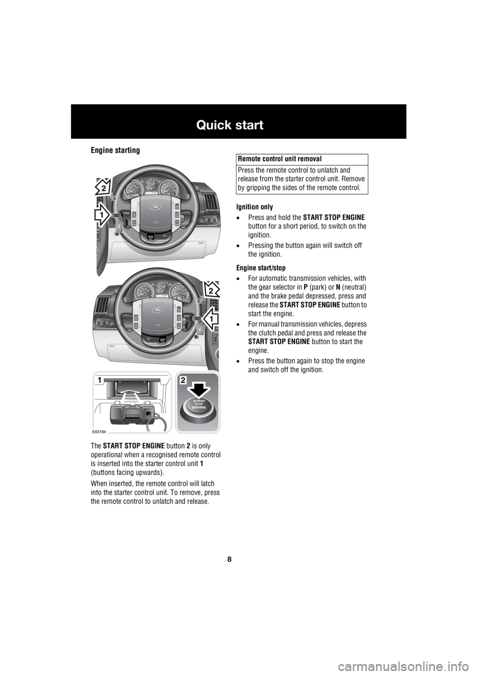
The START STOP ENGINE button 2 is only
operational when a rec ognised remote control
is inserted into the starter control unit 1
(buttons facing upwards).
When inserted, the remo te control will latch
into the starter control unit. To remove, press
the remote control to unlatch and release. Ignition only
• Press and hold the START STOP ENGINE
button for a short period, to switch on the
ignition.
• Pressing the button again will switch off
the ignition.
Engine start/stop
• For automatic transmission vehicles, with
the gear selector in P (park) or N (neutral)
and the brake pedal de pressed, press and
release the START STOP ENGINE button to
start the engine.
• For manual transmission vehicles, depress
the clutch pedal and press and release the
START STOP ENGINE button to start the
engine.
• Press the button again to stop the engine
and switch off the ignition.
1
EXT C23EXT F72EXT C21
EXT C23EXT F72EXT C21
1
1
2
2
E83184
2
Remote control unit removal
Press the remote control to unlatch and
release from the starter control unit. Remove
by gripping the sides of the remote control.
Page 2738 of 3229
18
Quick start
L
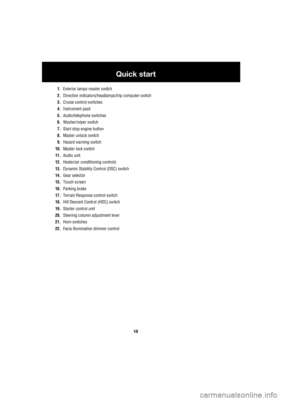
1. Exterior lamps master switch
2. Direction indicators/headlam ps/trip computer switch
3. Cruise control switches
4. Instrument pack
5. Audio/telephone switches
6. Washer/wiper switch
7. Start stop engine button
8. Master unlock switch
9. Hazard warning switch
10. Master lock switch
11. Audio unit
12. Heater/air conditioning controls
13. Dynamic Stability Control (DSC) switch
14. Gear selector
15. Touch screen
16. Parking brake
17. Terrain Response control switch
18. Hill Descent Control (HDC) switch
19. Starter control unit
20. Steering column adjustment lever
21. Horn switches
22. Facia illumination dimmer control