2006 LAND ROVER FRELANDER 2 brake
[x] Cancel search: brakePage 2300 of 3229
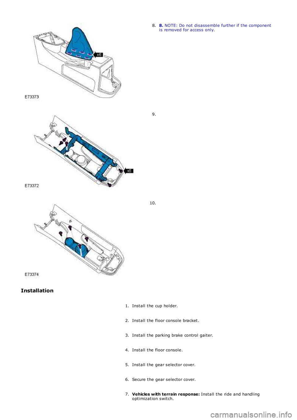
8. NOTE: Do not dis ass embl e further if t he componenti s removed for acces s onl y.8.
9.
10.
Installation
Inst all t he cup hol der.1.
Inst all t he fl oor consol e bracket .2.
Inst all t he parking brake control gai ter.3.
Inst all t he fl oor consol e.4.
Inst all t he gear s elector cover.5.
Secure t he gear s elector cover.6.
Vehicles w ith terrain response: Inst all t he ri de and handl ingopti mizat ion s wit ch.7.
Page 2369 of 3229
The rear glas s panel i s fixed in pos i ti on and bonded t o t he roof openi ng panel frame us i ng a PU adhes ive. The forwardglas s panel i s dri ven into pos i ti on by a pair of heli xed cables . The helixed cables are abl e t o pus h or pul l the forward glas spanel i nt o t he requi red pos it ion.
The roof openi ng panel al so cont ai ns 2 i nt egral, manuall y operat ed sunbli nds and 2 drai n hoses . The drai n hoses areconnected t o t he cent er of the frame above t he B pi ll ars . The drain hos es run through the cant rail s and down t he C pi llarst o all ow water coll ect ed in the frame to escape.
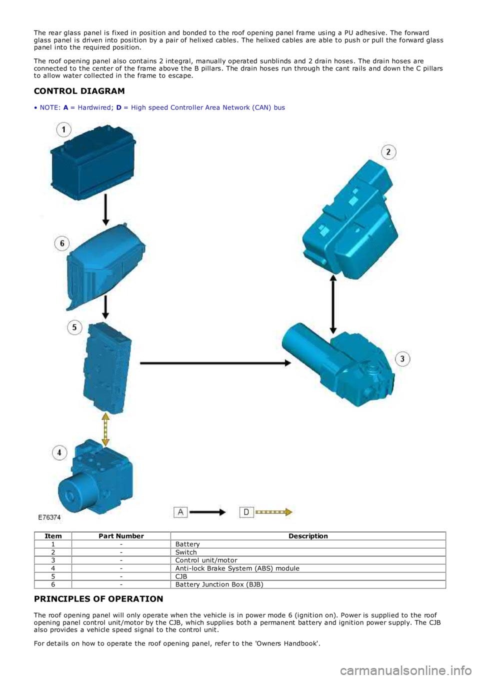
CONTROL DIAGRAM
• NOTE: A = Hardwi red; D = High speed Controll er Area Network (CAN) bus
ItemPart NumberDescription
1-Bat tery
2-Swi tch3-Cont rol unit /mot or
4-Ant i-lock Brake Sys tem (ABS) module
5-CJB6-Bat tery Juncti on Box (BJB)
PRINCIPLES OF OPERATION
The roof openi ng panel wi ll only operat e when t he vehi cle i s in power mode 6 (i gnit ion on). Power is suppli ed to the roofopeni ng panel cont rol unit /motor by t he CJB, whi ch suppli es bot h a permanent bat tery and ignit ion power s uppl y. The CJBals o provi des a vehi cl e s peed si gnal t o t he cont rol unit .
For det ails on how t o operate the roof opening panel, refer t o t he 'Owners Handbook'.
Page 2522 of 3229
Bury St EdmundsSuffol kIP32 7DXTelephone (01284) 760791www.sat a.com
Henkel Loct it e Adhesi ves Li mi ted
Technologies Hous eW ood Lane EndHemel Hempst eadHert fordshi reHP2 4RQTelephone (01442) 278000www.locti te.co.uk
Teros on
Henkel LtdApollo Court2 Bi shops Square Bus ines s ParkHatfiel dHert fordshi reAL10 9EYTelephone (01707) 635000www.henkel.co.uk
Underbody sealer
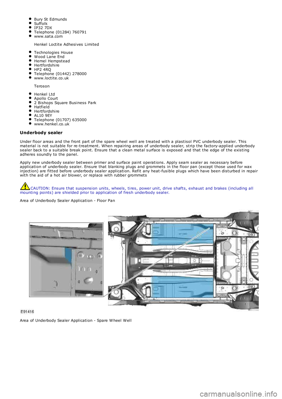
Under floor areas and t he front part of the spare wheel wel l are t reat ed wit h a pl ast is ol PVC underbody sealer. Thi smat erial i s not sui table for re-treatment . W hen repairing areas of underbody s ealer, s t ri p t he factory-appl ied underbodys eal er back t o a s uit able break poi nt. Ens ure t hat a clean met al s urface is expos ed and that t he edge of t he exis t ingadheres s oundly to the panel.
Apply new underbody s eal er bet ween pri mer and s urface paint operat ions . Appl y s eam seal er as neces sary beforeappl icati on of underbody s ealer. Ens ure that blanking plugs and grommets in t he floor pan (except t hose used for waxinject ion) are fi tt ed before underbody s ealer appl icati on. Refit any heat-fus ibl e plugs which have been dis t urbed in repairwit h t he aid of a hot ai r blower, or repl ace wit h rubber grommet s
CAUTION: Ens ure t hat sus pens i on uni ts , wheels , ti res , power uni t, drive s haft s, exhaus t and brakes (including al lmounti ng points ) are s hi elded pri or to appl icat ion of fres h underbody s eal er.
Area of Underbody Sealer Appl icati on - Floor Pan
Area of Underbody Sealer Appl icati on - Spare W heel W el l
Page 2546 of 3229
Publis hed: 11-May-2011
Front End Sheet Metal Repairs - Front Side Member and Suspension Top Mount
AssemblyRemoval and Ins tallat ion
Removal
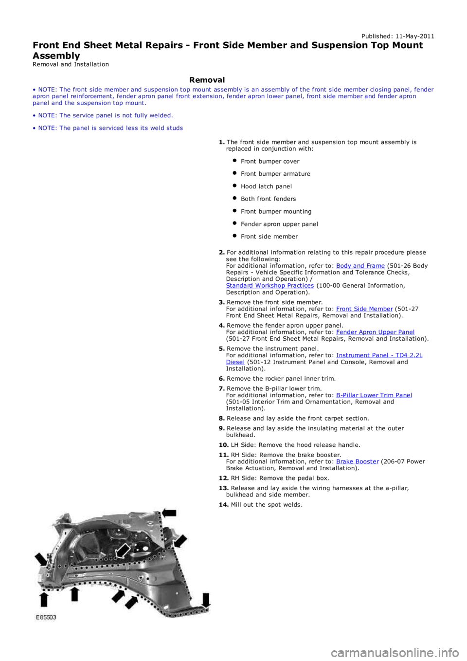
• NO TE: The front s ide member and suspens ion t op mount as sembly is an ass embly of the front s ide member closing panel, fenderapron panel reinforcement, fender apron panel front ext ens ion, fender apron lower panel, front s ide member and fender apronpanel and the s uspens ion t op mount .
• NO TE: The service panel is not fully welded.
• NO TE: The panel is serviced les s it s weld s tuds
1. The front side member and suspens ion t op mount as sembly isreplaced in conjunct ion wit h:
Front bumper cover
Front bumper armat ure
Hood lat ch panel
Both front fenders
Front bumper mount ing
Fender apron upper panel
Front side member
2. For addit ional information relating t o t his repair procedure pleas es ee t he following:For addit ional informat ion, refer to: Body and Frame (501-26 BodyRepairs - Vehicle Specific Informat ion and Tolerance Checks ,Des cript ion and O perat ion) /Standard W orkshop Pract ices (100-00 General Informat ion,Des cript ion and O perat ion).
3. Remove t he front s ide member.For addit ional informat ion, refer to: Front Side Member (501-27Front End Sheet Met al Repairs, Removal and Ins t allat ion).
4. Remove t he fender apron upper panel.For addit ional informat ion, refer to: Fender Apron Upper Panel(501-27 Front End Sheet Met al Repairs, Removal and Ins t allat ion).
5. Remove t he ins t rument panel.For addit ional informat ion, refer to: Inst rument Panel - TD4 2.2LDiesel (501-12 Inst rument Panel and Cons ole, Removal andIns t allat ion).
6. Remove t he rocker panel inner t rim.
7. Remove t he B-pillar lower t rim.For addit ional informat ion, refer to: B-Pillar Lower Trim Panel(501-05 Int erior Trim and Ornamentat ion, Removal andIns t allat ion).
8. Releas e and lay as ide t he front carpet sect ion.
9. Releas e and lay as ide t he ins ulat ing mat erial at t he out erbulkhead.
10. LH Side: Remove the hood releas e handle.
11. RH Side: Remove the brake boost er.For addit ional informat ion, refer to: Brake Boost er (206-07 PowerBrake Act uat ion, Removal and Ins t allat ion).
12. RH Side: Remove the pedal box.
13. Release and lay aside t he wiring harnes ses at t he a-pillar,bulkhead and s ide member.
14. Mill out t he spot welds .
Page 2550 of 3229
Publi s hed: 11-May-2011
Front End Sheet Metal Repairs - Front Side Member
Removal and Inst all ati on
• NOTE: The front s ide member i s s erviced as a s eparate weld on panel. This procedure is to fit a long s ect ion cut from thes ervice panel, dis carding t he rear part .
• NOTE: The s ervice panel is not ful ly wel ded.
• NOTE: The s ect ion must be made at leas t 20mm forward of the l aser wel d.
1. The front s i de member is replaced in conjuncti on wit h:
Front bumper cover
Front bumper
Hood lat ch panel
Both front fenders
Front bumper mount ing
Front s ide member clos ing panel
Fender apron panel front reinforcement
Fender apron l ower panel
• NOTE: It is al so neces sary t o remove t he engine and s us pens ion as an as s embly.
2. For addit ional informati on rel at ing to this repair procedurepleas e s ee t he foll owing:For addi ti onal informat ion, refer t o: Body and Frame (501-26Body Repai rs - Vehi cl e Speci fic Informat ion and ToleranceChecks , Descripti on and Operat ion) /Standard W orks hop Practi ces (100-00 General Informat ion,Des cript ion and Operat ion).
3. Remove the front s ide member clos ing panel.For addi ti onal informat ion, refer t o: Front Side Member Cl os i ngPanel (501-27 Front End Sheet Met al Repai rs , Removal andIns t allat ion).
4. Remove the radi ator cool ing pack.For addi ti onal informat ion, refer t o: Radiator (303-03A Engi neCooling - I6 3.2L Petrol, Removal and Ins tall ati on).
5. Remove the engine and front s uspens ion as an as s embly.
6. Rel eas e and lay as ide t he brake pipe.
7. LH Side: Release the bat tery juncti on box and posi ti on asi de.
8. LH Side: Remove the ai r int ake pi pe.
9. LH Side: Release and lay as ide t he brake pi pe at the si demember.
10. LH Side: Remove the ant i-Lock brake s ys tem (ABS) Module.For addi ti onal informat ion, refer t o: Anti -Lock Brake Syst em(ABS) Module (206-09A Ant i-Lock Control, Removal andIns t allat ion).
11. RH Side: Remove the winds hi eld was her res ervoir.For addi ti onal informat ion, refer t o: W i nds hiel d W as herRes ervoi r (501-16 W i pers and W as hers , Removal andIns t allat ion).
12. RH Side: Remove the engi ne mount ing bracket .For addi ti onal informat ion, refer t o: Engi ne Mount RH (303-01BEngine - TD4 2.2L Dies el, Removal and Ins tall ati on).
13. RH Side: Remove the fender apron brake pipes .
14. RH Side: Remove the fender apron A/C pipe.
15. Rel eas e and l ay as ide t he ins ulat ing mat eri al at t hebulkhead.
16. Rel eas e and l ay as ide t he wiring harnes s .
Page 2554 of 3229
Publi s hed: 11-May-2011
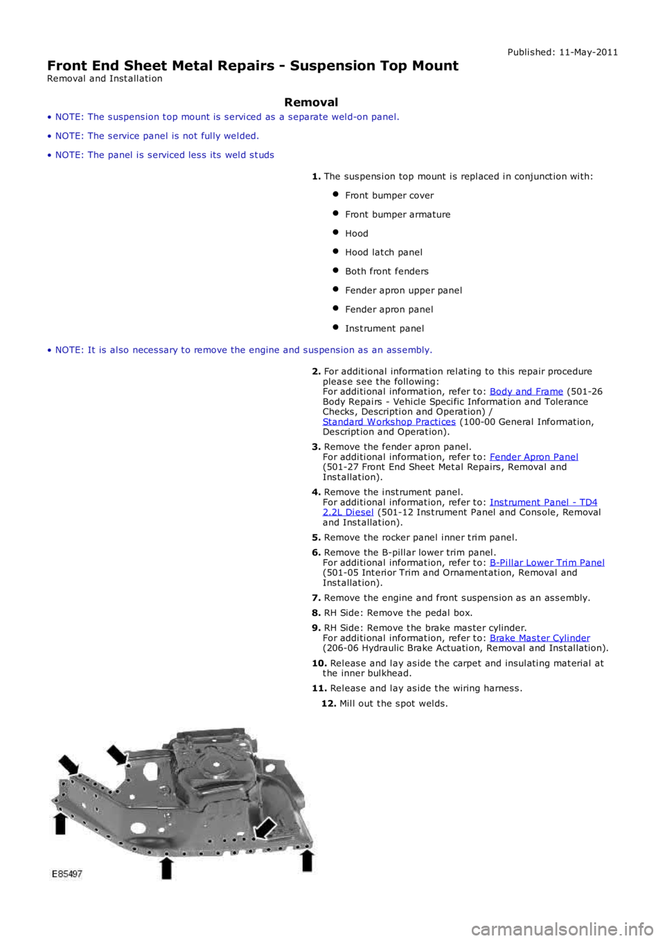
Front End Sheet Metal Repairs - Suspension Top Mount
Removal and Inst all ati on
Removal
• NOTE: The s uspens ion t op mount is s ervi ced as a s eparate wel d-on panel.
• NOTE: The s ervice panel is not ful ly wel ded.
• NOTE: The panel i s s erviced les s i ts wel d s t uds
1. The sus pens i on top mount i s repl aced i n conjunct ion wi th:
Front bumper cover
Front bumper armature
Hood
Hood lat ch panel
Both front fenders
Fender apron upper panel
Fender apron panel
Ins t rument panel
• NOTE: It is al so neces sary t o remove t he engine and s us pens ion as an as s embly.
2. For addit ional informati on rel at ing to this repair procedurepleas e s ee t he foll owing:For addi ti onal informat ion, refer t o: Body and Frame (501-26Body Repai rs - Vehi cl e Speci fic Informat ion and ToleranceChecks , Descripti on and Operat ion) /Standard W orks hop Practi ces (100-00 General Informat ion,Des cript ion and Operat ion).
3. Remove the fender apron panel.For addi ti onal informat ion, refer t o: Fender Apron Panel(501-27 Front End Sheet Met al Repairs , Removal andIns t allat ion).
4. Remove the i nst rument panel.For addi ti onal informat ion, refer t o: Ins t rument Panel - TD42.2L Di esel (501-12 Ins t rument Panel and Cons ole, Removaland Ins t allat ion).
5. Remove the rocker panel i nner t ri m panel.
6. Remove the B-pill ar lower trim panel .For addi ti onal informat ion, refer t o: B-Pi ll ar Lower Tri m Panel(501-05 Int eri or Trim and Ornament ati on, Removal andIns t allat ion).
7. Remove the engine and front s uspens ion as an as s embly.
8. RH Side: Remove t he pedal box.
9. RH Side: Remove t he brake mas ter cylinder.For addi ti onal informat ion, refer t o: Brake Mas t er Cyli nder(206-06 Hydraulic Brake Actuati on, Removal and Ins t al lat ion).
10. Rel eas e and l ay as ide t he carpet and ins ul ati ng mat erial att he inner bul khead.
11. Rel eas e and l ay as ide t he wiring harnes s .
12. Mil l out t he s pot wel ds.
Page 2649 of 3229
Publ is hed: 11-May-2011
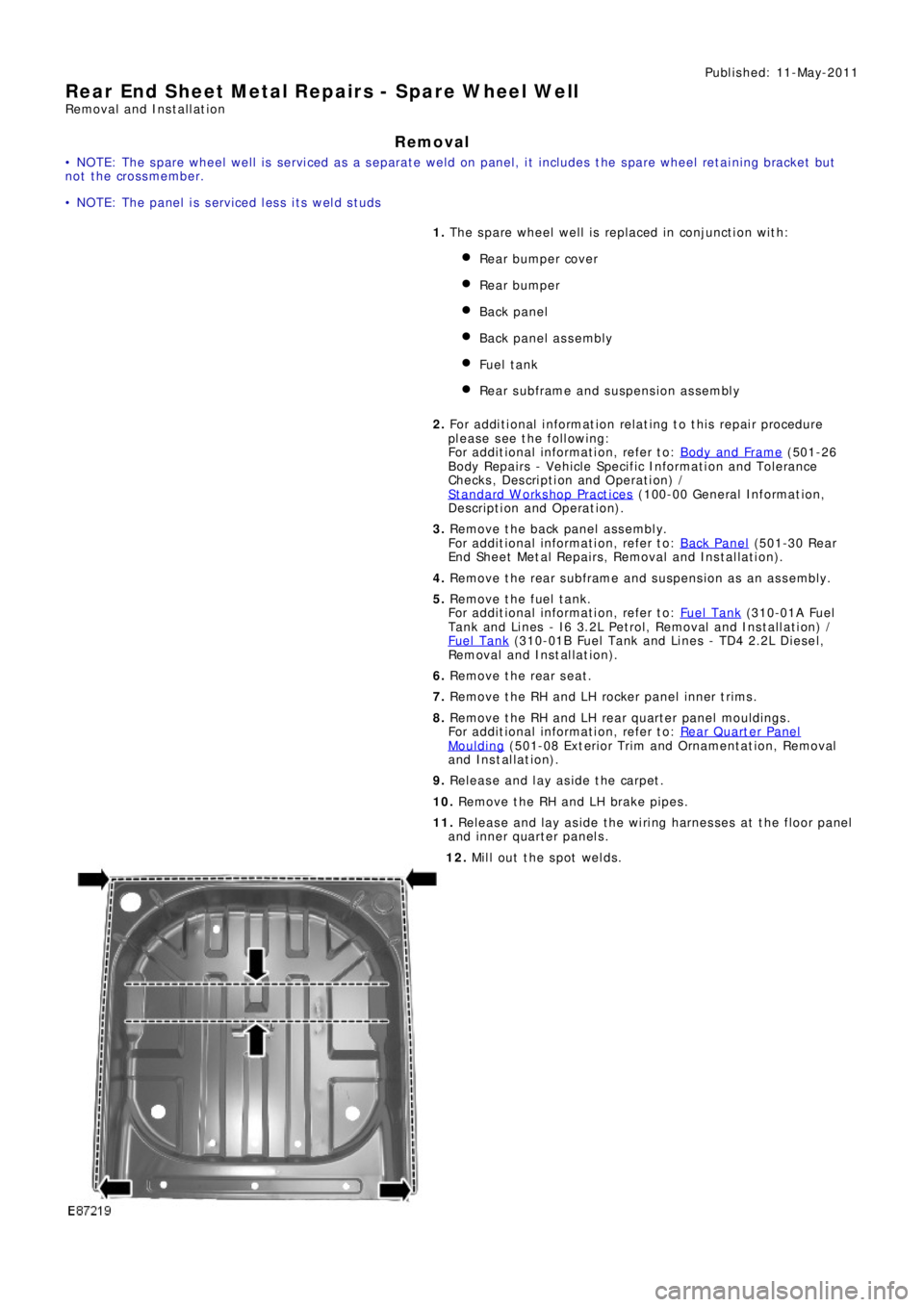
Rear End Sheet Metal Repairs - Spare Wheel Well
Removal and Installation
Removal
• NOTE: The spare wheel well is serviced as a separate weld on panel, it includes the spare wheel retaining bracket but
not the crossmember.
• NOTE: The panel is serviced less its weld studs
1. The spare wheel well is replaced in conjunction with:
Rear bumper cover
Rear bumper
Back panel
Back panel assembly
Fuel t ank
Rear subframe and suspension assembly
2. Fo r a d d i t i o na l i nf o rma t i o n re l a t i ng t o t hi s re p a i r p ro ce d ure
please see the following:
Fo r a d d i t i o na l i nf o rma t i o n, re f e r t o : Body and Frame
(501-26
Body Repairs - Vehicle Specific Information and Tolerance
Checks, Description and Operation) /
St a nd a rd W o rks ho p P ra ct i ce s
(100-00 Ge ne ra l I nf o rma t i o n,
Description and Operation).
3. Remove the back panel assembly.
Fo r a d d i t i o na l i nf o rma t i o n, re f e r t o : Back Panel
(501-30 Rear
End Sheet Metal Repairs, Removal and Installation).
4. Remove the rear subframe and suspension as an assembly.
5. Remove the fuel tank.
Fo r a d d i t i o na l i nf o rma t i o n, re f e r t o : Fuel Tank
(310-01A Fuel
Tank and Lines - I6 3.2L Petrol, Removal and Installation) /
Fuel Tank
(310-01B Fuel Tank and Li nes - TD4 2.2L Di es el,
Removal and Installation).
6. Remove the rear seat.
7. Remove the RH and LH rocker panel inner trims.
8. Remove the RH and LH rear quarter panel mouldings.
Fo r a d d i t i o na l i nf o rma t i o n, re f e r t o : Rear Quarter Panel
Moulding (501-08 Ext eri or Trim and Ornament at i on, Removal
and Installation).
9. Release and lay aside the carpet.
10. Remove the RH and LH brake pipes.
11. Release and lay aside the wiring harnesses at the floor panel
and inner quarter panels.
12. Mill out the spot welds.
Page 2685 of 3229
Publ is hed: 11-May-2011
Rear End Sheet Metal Repairs - Inner Quarter Panel and Wheelhouse
Removal and Installation
Removal
• NOTE: The inner quarter panel and wheelhouse is an assembly of the inner quarter panel, rear wheelhouse inner, rear
wheelhous e out er and t he rear lamp mount ing panel.
• NOTE: The service panel is not fully welded.
• NOTE: The panel is sectioned to avoid disturbing the roof panel.
1. The inner quarter panel and wheelhouse is replaced in
conjunct ion wit h:
Rear bumper cover
Rear bumper
Quarter panel
Rear door
Quarter glass
Rear subframe and suspension assembly
2. Fo r a d d i t i o na l i nf o rma t i o n re l a t i ng t o t hi s re p a i r p ro ce d ure
please see the following:
Fo r a d d i t i o na l i nf o rma t i o n, re f e r t o : Body and Frame
(501-26
Body Repairs - Vehicle Specific Information and Tolerance
Checks, Description and Operation) /
St a nd a rd W o rks ho p P ra ct i ce s
(100-00 Ge ne ra l I nf o rma t i o n,
Description and Operation).
3. Remove the quarter panel.
Fo r a d d i t i o na l i nf o rma t i o n, re f e r t o : Quarter Panel
(501-30
Rear End Sheet Metal Repairs, Removal and Installation).
4. Remove the rear subframe / suspension as an assembly.
5. Remove the brake pipe.
6. RH Only: Release and lay aside the fuel vent hose.
7. Remove the rear seat backrest.
Fo r a d d i t i o na l i nf o rma t i o n, re f e r t o : Front Seat Backres t Heat er
Ma t (501-10 Seating, Removal and Installation).
8. Release and lay aside the wiring harness.