2006 LAND ROVER FRELANDER 2 brake
[x] Cancel search: brakePage 2050 of 3229
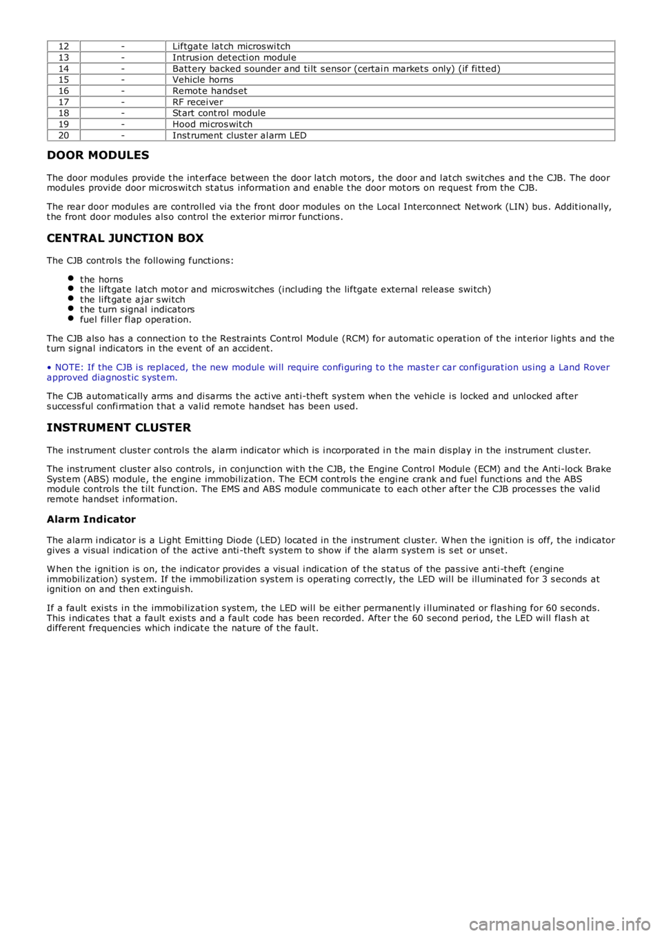
12-Liftgat e lat ch micros wi tch
13-Intrus i on det ecti on modul e
14-Batt ery backed s ounder and ti lt s ensor (certai n market s only) (if fi tt ed)15-Vehicle horns
16-Remot e hands et
17-RF recei ver18-St art cont rol module
19-Hood mi cros wit ch
20-Inst rument clus ter al arm LED
DOOR MODULES
The door modul es provide t he int erface bet ween the door lat ch mot ors , the door and lat ch swit ches and t he CJB. The doormodules provi de door mi cros wit ch st atus informati on and enabl e t he door mot ors on reques t from the CJB.
The rear door modul es are controll ed via t he front door modules on the Local Interconnect Net work (LIN) bus . Addit ionally,t he front door modules als o control the ext erior mi rror functi ons .
CENTRAL JUNCTION BOX
The CJB cont rol s the foll owing funct ions:
t he hornst he li ft gat e l at ch mot or and micros wit ches (i ncl udi ng the liftgat e external rel ease swi tch)t he li ft gat e ajar s wi tcht he turn s ignal indicatorsfuel fill er fl ap operati on.
The CJB als o has a connect ion t o t he Rest rai nts Cont rol Modul e (RCM) for automat ic operat ion of t he int eri or l ight s and thet urn s ignal indicators in the event of an accident.
• NOTE: If the CJB i s repl aced, the new modul e wi ll require confi guring t o t he mas ter car configurat ion us ing a Land Roverapproved diagnos t ic s yst em.
The CJB automat ically arms and di sarms t he acti ve ant i-theft sys t em when t he vehi cl e i s locked and unl ocked afters uccess ful confi rmat ion t hat a vali d remot e handset has been us ed.
INSTRUMENT CLUSTER
The ins t rument clus ter cont rol s the al arm indicat or whi ch is i ncorporated i n t he main dis play in the ins trument cl us t er.
The ins t rument clus ter als o controls , in conjuncti on wit h t he CJB, t he Engine Control Modul e (ECM) and t he Ant i-lock BrakeSyst em (ABS) module, the engine immobi lizat ion. The ECM cont rol s t he engi ne crank and fuel functi ons and the ABSmodule controls t he t il t funct ion. The EMS and ABS modul e communicate to each ot her after t he CJB proces s es the val idremot e handset i nformat ion.
Alarm Indicator
The alarm i ndi cat or is a Li ght Emit ti ng Diode (LED) locat ed in the ins trument cl us t er. W hen t he i gni ti on is off, t he i ndi cat orgives a vi sual indicati on of the act ive anti -t heft s ys tem to show if t he alarm s yst em is s et or uns et .
W hen t he i gni ti on is on, t he indicator provi des a vis ual i ndi cat ion of t he s tat us of the pas s ive anti -t heft (engi neimmobili zat ion) s yst em. If the i mmobil izati on s ys t em i s operati ng correct ly, the LED wil l be ill uminat ed for 3 s econds atignit ion on and then ext ingui s h.
If a fault exi st s i n the immobi lizat ion s yst em, t he LED wil l be eit her permanent ly ill uminated or flas hing for 60 s econds.This i ndi cat es t hat a fault exis t s and a faul t code has been recorded. After t he 60 s econd peri od, t he LED wi ll flas h atdifferent frequenci es which indicat e the nat ure of t he faul t.
Page 2054 of 3229
it recei ves an alarm s ignal from t he CJB or the t il t s ens ort he power s upply or t he LIN bus link t o t he CJB is dis rupted.
The t ilt s ens or meas ures the l ongi tudinal and lat eral angl e of the vehicl e over a range of ±16 degrees from the hori zont al.W hen t he acti ve ant i-t heft s ys t em i s armed in volumet ri c mode, the t il t s ens or s tores the current vehi cl e angl es in it smemory and monit ors t he t il t sens or readings. If t he vehi cl e angle changes i n eit her di recti on by more t han the al armli mit , t he ti lt s ensor acti vat es t he s ounder.
If the al arm sys tem is act ive and t he batt ery or t he batt ery backed sounder is di sconnect ed, t he s ounder wil l operatewit hout the vi sual indicati on of the turn s ignal i ndicat ors fl as hing.
Global Open/Close
The global open/cl os e feature all ows the us er t o ful ly rais e/l ower t he wi ndows wit h a s ingle pres s of a remote hands etbutt on. The but ton must be press ed and held for more t han 2 s econds. Ei ther or bot h gl obal open/clos e functi ons can bedis abled us ing a Land Rover approved di agnos ti c s yst em.
• NOTE: Remote global cl os e i s not avai lable in cert ain markets , Nort h American Speci ficat ion (NAS) for exampl e.
Single Point Entry
The s ingle poi nt ent ry feature only unlocks the driver's door and the l iftgate, al l ot her doors remai n locked. A si ngle pres sof the unl ock but ton on the remote hands et wil l unl ock only the driver's door and t he li ft gate, a s econd pres s is requi red tounlock the remaini ng doors .
If the vehicle is double l ocked, the firs t pres s of the unlock butt on on t he remote hands et unl ocks t he dri ver's door and theli ft gate. The remai ning doors revert t o the si ngl e l ocked s tat e and can t herefore be unlocked us ing the i nteri or doorhandl es, t he remot e handset unlock butt on or t he unl ock swi tch on the i nst rument panel swi tchpack.
Changi ng from central locki ng to si ngle point ent ry can be carried out by pres s ing the l ock and unlock butt ons on t heremot e handset s imult aneousl y. The turn s ignal i ndicat ors wil l flas h t o confirm that t he functi on change has beenperformed.
Drive Away Locking
The dri ve away door l ocking feature locks the doors and the lift gat e i f they are unlocked when t he vehi cle reaches a cert ains peed.
On vehicles wi th aut omat ic t rans mis s ion, wit h al l t he doors , li ft gate and hood clos ed and t he gear s elector not in 'P' Parkor 'N' Neutral pos it ion, if t he CJB detects , via a high s peed CAN mes s age from t he Ant i-lock Brake Syst em (ABS) module,t hat t he vehi cle s peed is more t han 7 km/h (5 mph), the doors wil l aut omati cal ly l ock.
On vehicles wi th manual t rans mis s ion, wi th al l the doors , l ift gate and hood cl os ed, if t he CJB detects , via a high s peedCAN mes s age from t he ABS modul e, t hat the vehicle speed i s more than 7 km/h (5 mph), t he doors wi ll automat ically lock.
Remote Handset Additional Features
The remot e handset has convenience butt ons in addit ion to the l ock and unl ock but tons .
Pani c Alarm
The pani c alarm feature allows the us er to act ivate the vehicle alarm s yst em us ing the remote hands et. The 'panic but ton',identi fi ed by a t ri angl e s ymbol, can be pres s ed 3 t imes wit hi n 3 s econds or pres s ed and held for more than 3 seconds toact ivat e t he pani c alarm.
Global Open/Close
A gl obal open and clos e feat ure can be operat ed from t he remote hands et . This feature allows the vehicle windows t o beopened/cl os ed by a s ingle press of t he l ock or unlock butt on. The but ton must be press ed and held for more t han 2s econds t o act ivat e the gl obal open/clos e feat ure. The global open/cl ose feature i s not avail abl e i n all market s .
Liftgate Release
A l iftgat e rel eas e but ton can pres s ed t o unlock and rel eas e t he li ft gate latch only. This will operat e wi th the vehicle lockedand alarmed or unl ocked. If t he vehicle i s locked and alarmed, when t he l iftgate releas e butt on i s pres s ed, t he li ft gate canbe opened wit hout t ri ggering t he alarm s ys tem. W hen the liftgat e is subs equent ly clos ed, the al arm wil l be re-act ivated.
Headlamp Convenience
A headlamp conveni ence but ton can be press ed t o operat e the headlamps to as s is t departure or approach to the vehicle. As ingle press of the but ton wi ll operat e the headlamps for approxi mat el y 25 s econds , aft er whi ch ti me t hey wil lautomat ically turn off. A s econd press of t he butt on wi ll t urn off the headlamps i f the 25 second period has not beenreached. Pres s ing the s t op/s tart but ton wit hin t he 25 s econd period wi ll als o t urn off t he headlamp convenience feature.
Convenience mode
W hen t he vehicle i s unlocked us i ng the unl ock but ton on t he remote hands et , t he vehicl e's electrical s ys t em i ni ti atesconvenience mode. The foll owing s yst ems become acti ve:
Memory - s eat adjus t ment and mirror pos it ionInt eri or and ext erior l ighti ngAudio s ys temIns t rument clus ter mes s age cent reHornCigar li ght er/power socket .
Page 2058 of 3229
Publi s hed: 11-May-2011
Anti-Theft - Passive - Anti-Theft - Passive
Des cript ion and Operat ion
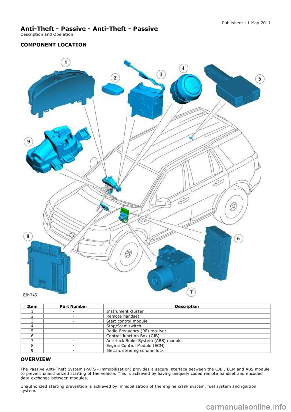
COMPONENT LOCATION
ItemPart NumberDescription1-Ins trument cl us t er
2-Remot e handset
3-St art control modul e4-St op/St art s wit ch
5-Radio Frequency (RF) recei ver
6-Cent ral Juncti on Box (CJB)7-Ant i-lock Brake Sys tem (ABS) module
8-Engine Cont rol Module (ECM)
9-El ect ri c s teeri ng col umn l ock
OVERVIEW
The Pass i ve Ant i-Theft Syst em (PATS - i mmobil izati on) provi des a s ecure int erface bet ween the CJB , ECM and ABS modulet o prevent unauthorized s tarti ng of the vehicle. This i s achi eved by havi ng uni quel y coded remote hands et and encodeddata exchange bet ween modules .
Unaut hori zed st art ing prevent ion i s achi eved by i mmobil izati on of the engine crank sys t em, fuel sys t em and i gni ti ons ys t em.
Page 2059 of 3229
The pass i ve ant i-theft sys t em us es the foll owing component s:
Remote hands et trans ponderCJBECMStart cont rol moduleIns t rument clus terABS moduleElectric s t eering column lock (if enabl ed).
• NOTE: On North Ameri can Specificat ion (NAS) vehi cles , a running change was int roduced during 2008 Model Y ear (MY ) t odis able t he electric st eering col umn lock. Under t he change, the i nternal elect ronics (print ed circuit board (PCB), motor,etc.) of t he l ock have been removed and t he lock has been dis abled i n t he car configurat ion fi le. The change i sincorporat ed on VIN (vehi cl e identi fi cat ion number) 082896, 085531, 085622, 085685, 085832, 085891, 085942, 085987,086049, 086081, 086123, 086178, 086276, 086287, 086309, 086363, 086383, 086389, 086398, 086403 and 091770onwards .
The s ys t em i s automat ic and requi res no input from t he dri ver. The engi ne management s yst em wil l onl y allow engi necrank when an aut horizati on data mess age is received from t he CJB. The engi ne st art s ys tem is init iat ed when thes tart/s top s wi tch and t he brake pedal (automat ic t rans mis s ion) or t he cl utch pedal (manual trans mi ss i on) are pres s eds imul taneous l y.
The engi ne management s ys tem (ECM) wi ll only al low engi ne crank, s park (petrol models only) and inject or funct ions whent he foll owing condit ions are met:
A hardwi red Park/Neutral si gnal i s received from the Trans mi ss i on Cont rol Module (TCM) (aut omati c t ransmis s iononly)A hardwi red ignit ion s ignal is recei ved from t he CJBA hardwi red crank reques t s ignal is recei ved from t he CJBEncrypt ed data exchange bet ween t he ins trument cl ust er and the ECM is verifi ed.
Before the CJB will s end t he hardwired igni ti on si gnal , it mus t s ati s factori ly complet e t he fol lowi ng:
Exchanged encrypt ed data wit h the st art control modul e t o validat e t he remot e hands et .
Addit ional ly, before the CJB will s end t he hardwired crank reques t s ignal i t mus t receive t he fol lowing si gnal s:
Brake s ignal from t he brake s wi tch (automat ic t rans mis s ion) or clutch s i gnal from the clut ch s wit ch (manualt ransmis s ion)Hardwi red t rans mis s ion in Park (P) s ignal from t he s elector lever ass embl y (aut omatic trans mi s si on only).
CONTROL DIAGRAM
• NOTE: A = Hardwi red; D = High speed CAN bus ; N = Medium s peed CAN bus ; O = LIN bus ; W = LF t rans mis s ion
Page 2061 of 3229
opened. The remot e handset i s removed from the st art control modul e by gentl y pushi ng the remote hands et int o t he st artcont rol module and releas ing. The s tart cont rol module mot or wil l then drive t he remot e hands et out from t he s lot as l ongas t he ignit ion i s off.
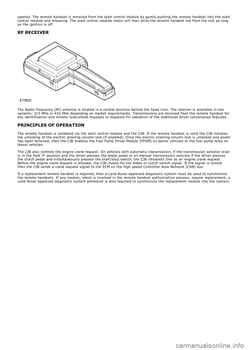
RF RECEIVER
The Radio Frequency (RF) antenna is locat ed i n a central pos it ion behind the head l iner. The receiver is avail able i n t wovariant s; 315 MHz or 433 MHz depending on market requirements . Trans mis s ions are received from the remote hands et forkey identi fi cat ion and remote lock/unlock request s or reques ts for operati on of the addit ional driver convenience feat ures.
PRINCIPLES OF OPERATION
The remot e handset i s validat ed via t he s tart cont rol module and t he CJB. If t he remot e handset i s valid the CJB i nit iatest he unl ocking of t he elect ric st eeri ng col umn lock (if enabled). Once t he electric st eering column lock is unl ocked and powerhas been removed, then t he CJB enabl es the Fuel Pump Dri ver Module (FPDM) on pet rol vehi cl es or the fuel pump relay ondies el vehicles .
The CJB als o control s t he engi ne crank reques t. On vehicl es wit h automat ic t rans mi ssion, i f the t rans mis s ion sel ect or l everis in t he Park 'P' pos it ion and the driver pres ses t he brake pedal or on manual t rans mis s ion vehicles i f the driver pres s est he cl utch pedal and s i mult aneous ly pres s es t he s tart /st op s wit ch, t he CJB i nt erprets t his as an engi ne crank request .Before the engi ne crank request i s all owed, t he CJB checks for t he brake or clut ch swit ch si gnal . If t he s ignal is correctt hen the CJB s ends a crank reques t s ignal t o t he ECM on the hi gh speed Controll er Area Network (CAN) bus .
If a replacement remot e hands et i s required, t hen a Land Rover approved diagnost ic sys tem mus t be us ed to s ynchronizet he remot e hands et s. If any module, which i s involved in the remote hands et aut hori zat ion proces s , require replacement, aLand Rover approved diagnos t ic s ys tem procedure is al s o required t o s ynchronize t he repl acement module into the s ys tem.
Page 2062 of 3229
Publi s hed: 11-May-2011
Anti-Theft - Passive - Anti-Theft - Passive
Diagnosi s and Tes ti ng
Principles of Operation
For a detail ed descripti on of the Pas s ive Ant i-Theft Sys t em (PATS), refer t o t he relevant Des cript ion and Operat ion secti onin the workshop manual.REFER to: Ant i-Theft - Pas s ive (419-01B Anti -Theft - Pas s ive, Descripti on and Operat ion).
Inspection and Verification
The best method t o confirm the correct operat ion of t he Pass i ve Ant i-Theft Syst em (PATS) is t o check t he LED (located i nt he cent er of t he ins t rument panel ). The LED s hould i ll uminate sol id for 3 s econds , when the i gnit ion s tat us is set t o ON,and t hen ext inguis h. Thi s validat es all PATS functi ons (i .e. the key t rans ponder matches a st ored key code, thechal lenge/res ponse sequence bet ween t he res pect ive modules was succes s ful res ult ing in t he EMS being enabled).
Ignition Fails to Operate
Check t hat the key i s correct ly i nserted i nto the s t art cont rol unit (SCU) and that i t is t he correct key for t he vehi cle (Keywil l be ejected from t he SCU i f it is not programmed or from anot her vehicl e). If the vehicle is an aut omati c, ens ure t hatt he Park pos it ion i s s el ect ed and if manual, ens ure it is in t he Neutral pos i ti on.
Check t hat the st art but ton circui t to the Cent ral Juncti on Box (CJB) i s not open circui t or s hort to ground.
Check t hat the CAN network is not mal functi oni ng, i .e. open circuit or s hort circui t. This woul d mean t hat the CJB, ECM andIns t rument Clus t er woul d be unabl e t o communicate. Check thes e modules for relat ed DTCs and refer t o relevant DTCIndex.
Engine Fails to Crank
The immobili zer s t atus i ndi cat ion LED i s dis played i n the bot tom left of the i nst rument pack. W hen the key i s i ns ert ed i nt ot he SCU, t he LED wi ll be t urned on for 3 s econds and t hen turned off. The LED will flas h s lowl y (once every 2 seconds ) i ft he vehi cl e is immobi lis ed (t ransponder not approved). Addit ionall y the di agnos ti c syst em s hould be us ed t o check forDiagnost ic Troubl e Codes (DTCs ) from the CJB, ins trument cl ust er, ECM and the ABS modul e.
One potent ial occurrence for the vehicl e fai ling to crank on an Automat ic Trans mi s sion coul d be due t o t he Locked in parks wit ch.
Check t he Crank reques t circui t from t he CJB t o ECM for short ci rcuit or open circuit .
Check t he St art er Rel ay Circuit .
Check t hat the St eeri ng Col umn Lock (SCL) is operat ing correctl y. Ins erti ng t he key should drive t he SCL t o un-l ock ands teeri ng wheel should move freel y.
Check t he CAN net work i s not malfunct ioning, i.e. the CAN ci rcuit i s open or short ci rcuit . Thi s would mean that t he CJB,ins t rument clus ter, ECM or ABS module would not be abl e t o communicate res ul ti ng in no chal lenge being made from t hemodules for the Immobil is ati on data.
Als o on an Aut omat ic, check the CAN network between t he CJB and the Transmis s ion Control Modul e (TCM). The CJB usest he "LockedInP" s ignal transmit ted by t he TCM to det ermi ne if t he t rans mis s ion i s in Park before all owing crank, the CJBus es a value of 0x01, i f the CJB s ees a value l ess than t his i t wil l not al low crank, and key wil l not be ejected from SCU.
For a manual gearbox t he clut ch pedal has to be de-pres s ed, hence check t he CAN network between t he CJB and t he ECMt o ensure t he cl utch i s depress ed, Clut chPedal Swit ch75pct = TRUE and Cl ut chPedalPress ed2 = True. The Vehicl e wil l notcrank unti l thes e s ignals are s et.
On an Aut omati c vehi cl e, check t he CAN network between t he ABS module and the CJB. The CJB uses a s ignal"BrakePedalActi ve" t o det ermi ne if t he brake pedal has been depres sed in order t o allow t he engine t o crank. The CJB us esa value = TRUE i f the CJB does not receive t hi s s ignal, i t wil l not al low t he crank reques t output.
Engine Cranks But Will Not Start
If the engine i s cranking i t means that t he EMS has pass ed t he authori s at ion required wit h t he CJB. If thi s authori s at ionfai led, the ECM would not engage the s t art er relay. Thi s coul d be confi rmed by verifyi ng t he LED in the l eft of t heIns t rument pack bei ng il lumi nat ed for 3 seconds on Key ins ert ion, or by reading DTCs from t he CJB or t he ECM.
In all cases of s us pected non-st art i s sues , the most l ogical fail ure modes s houl d be el imi nat ed first . i.e.
1. Check al l relevant suppli es and grounds to the relevant modul es are ok.2. Note any unus ual behavi our from other s yst ems /funct ionali ty.3. Note any funct ions t hat are not operati ng as expect ed.
Fault Codes/DTCs
For the vari ous PATS modes of operat ion/fail ures l is ted i n t he t abl e, t he CJB wi ll store a DTC whi ch wil l not be shown t ot he cus t omer.
W hen t he Key i s ins ert ed and ignit ion st atus ON is achieved, if t he s tart aut horis ation pas ses , the LED in t he bott om leftof the ins trument cl us t er will i ll uminate for 3 s econds t hen go off. If st art aut horis ati on fai ls , the LED wil l conti nue to fl as hevery 2 s econds . Pleas e s ee tabl e below for a li s t of fault codes that wil l be s tored under cert ain condi ti ons. For addi ti onalinformat ion.REFER to: St art ing Syst em (303-06A St art ing Sys tem - I6 3.2L Petrol, Di agnos is and Tes ti ng) /
Page 2069 of 3229
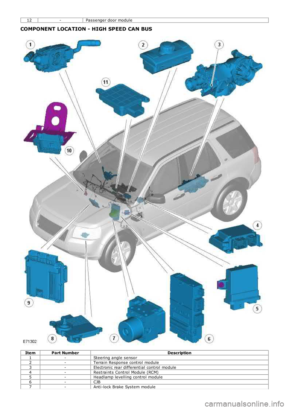
12-Pas s enger door modul e
COMPONENT LOCATION - HIGH SPEED CAN BUS
ItemPart NumberDescription
1-Steeri ng angl e s ensor2-Terrai n Respons e cont rol module
3-Elect roni c rear different ial cont rol module
4-Res t rai nt s Control Modul e (RCM)5-Headl amp levell ing control modul e
6-CJB
7-Ant i-lock Brake Sys tem module
Page 2299 of 3229
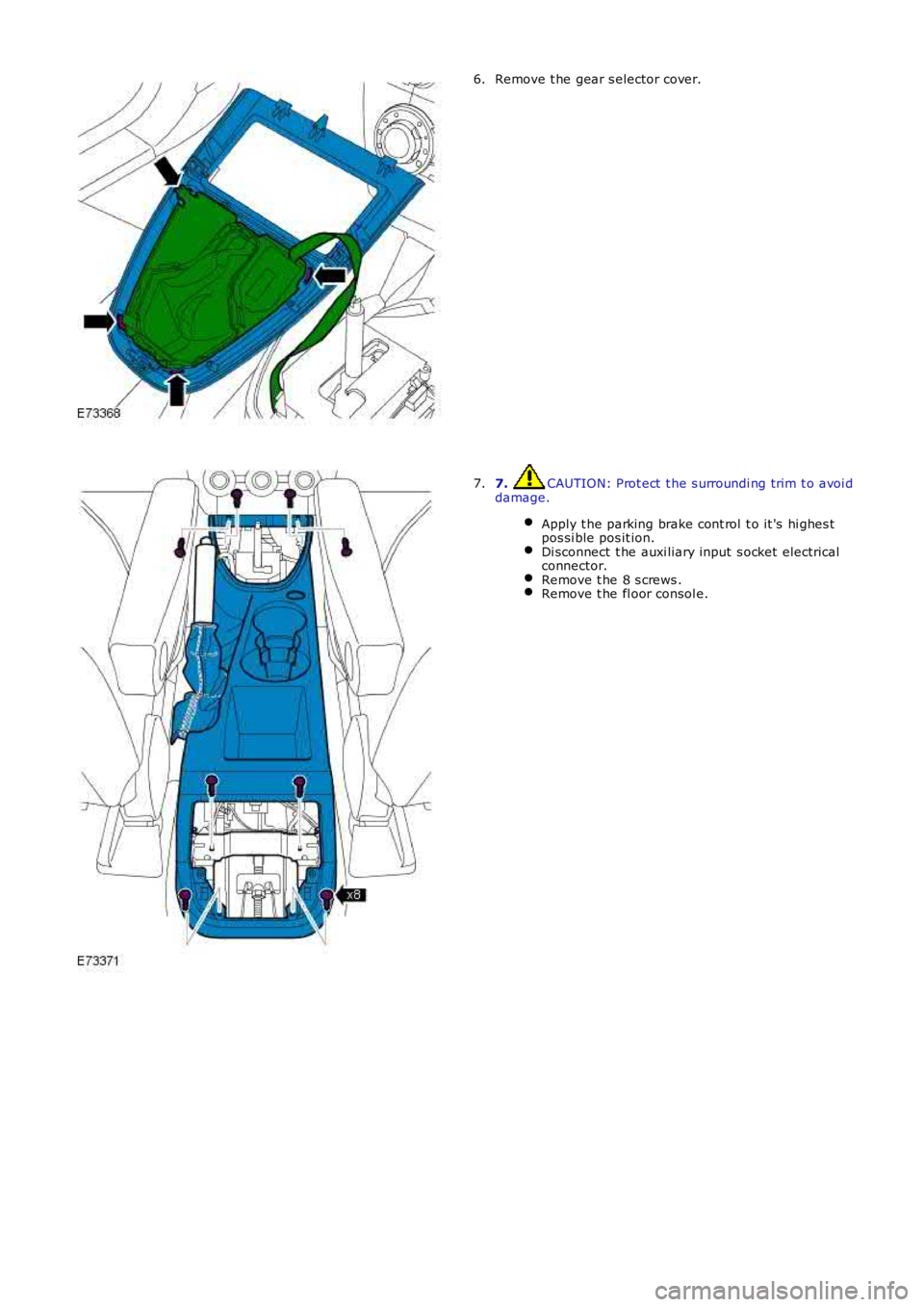
Remove t he gear s elector cover.6.
7. CAUTION: Prot ect t he s urroundi ng trim t o avoi ddamage.
Apply t he parking brake cont rol t o it 's hi ghes tpos si ble pos it ion.Di sconnect t he auxi liary input s ocket electricalconnector.Remove t he 8 s crews .Remove t he fl oor consol e.
7.