2006 LAND ROVER FRELANDER 2 brake
[x] Cancel search: brakePage 1768 of 3229
and t ransmit s t he engi ne s peed s i gnal t o the ins trument cl us t er on the medi um s peed CAN bus . The s ignal i s received byt he ins trument cl ust er microproces s or and t he output from the microproces sor dri ves the t achomet er.
Engine Temperature Gage
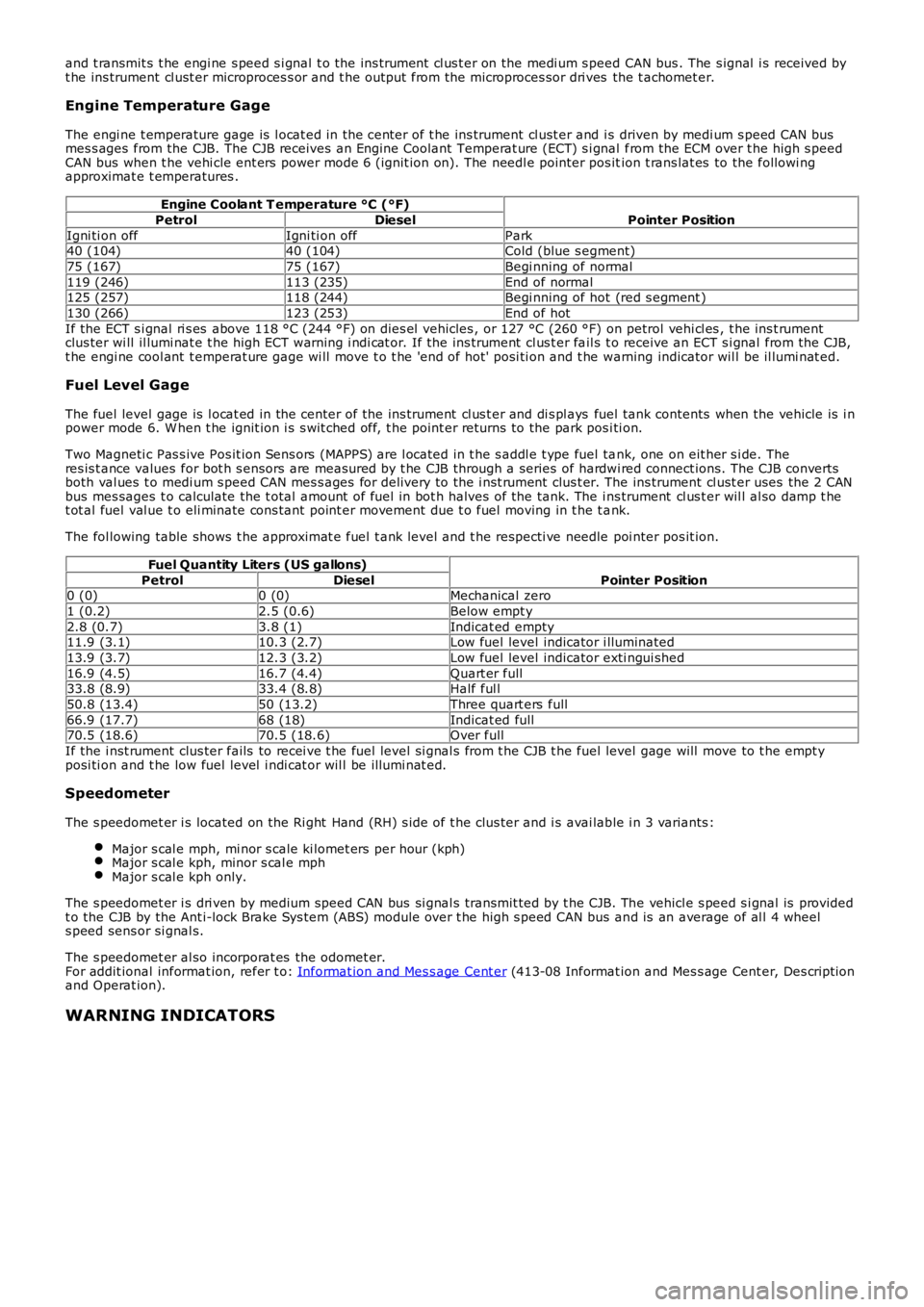
The engi ne t emperature gage is l ocat ed in the center of t he ins trument cl ust er and is driven by medi um s peed CAN busmes s ages from the CJB. The CJB receives an Engine Coolant Temperat ure (ECT) s i gnal from the ECM over t he high s peedCAN bus when t he vehi cle ent ers power mode 6 (ignit ion on). The needl e pointer pos ition t rans lat es to the followi ngapproximat e t emperatures .
Engine Coolant T emperature °C (°F)
Pointer PositionPetrolDiesel
Igni ti on offIgni ti on offPark40 (104)40 (104)Cold (blue s egment)
75 (167)75 (167)Begi nning of normal
119 (246)113 (235)End of normal125 (257)118 (244)Begi nning of hot (red s egment )
130 (266)123 (253)End of hot
If the ECT s i gnal ri s es above 118 °C (244 °F) on dies el vehicles , or 127 °C (260 °F) on petrol vehi cl es , t he ins t rumentclus ter wi ll il lumi nat e t he high ECT warning i ndi cat or. If the ins trument cl us t er fail s t o receive an ECT s i gnal from the CJB,t he engi ne cool ant t emperat ure gage wi ll move t o t he 'end of hot' posi ti on and t he warning indicator wil l be il lumi nat ed.
Fuel Level Gage
The fuel level gage is l ocat ed in the center of the ins trument cl us t er and di s pl ays fuel tank contents when the vehicle is i npower mode 6. W hen t he ignit ion i s s wit ched off, t he point er returns to the park posi ti on.
Two Magneti c Pas s ive Pos it ion Sens ors (MAPPS) are l ocated in t he s addl e t ype fuel tank, one on eit her s i de. Theres is t ance values for bot h s ensors are measured by t he CJB through a series of hardwi red connect ions. The CJB convertsboth val ues t o medi um s peed CAN mes s ages for delivery to the i nst rument clus t er. The ins trument cl ust er uses the 2 CANbus mes sages t o calculate the t otal amount of fuel in bot h halves of the tank. The ins trument cl us t er wil l al so damp t het ot al fuel val ue t o eli minate cons tant point er movement due t o fuel moving in t he t ank.
The fol lowing table shows t he approximat e fuel t ank level and t he respecti ve needle poi nter pos it ion.
Fuel Quantity Liters (US gallons)
Pointer PositionPetrolDiesel0 (0)0 (0)Mechanical zero
1 (0.2)2.5 (0.6)Below empt y
2.8 (0.7)3.8 (1)Indicat ed empty11.9 (3.1)10.3 (2.7)Low fuel level indicator i lluminated
13.9 (3.7)12.3 (3.2)Low fuel level indicator exti ngui shed
16.9 (4.5)16.7 (4.4)Quart er full33.8 (8.9)33.4 (8.8)Half ful l
50.8 (13.4)50 (13.2)Three quart ers full
66.9 (17.7)68 (18)Indicat ed full70.5 (18.6)70.5 (18.6)Over full
If the i nst rument clus ter fails to recei ve t he fuel level si gnal s from t he CJB t he fuel level gage will move to t he empt yposi ti on and t he low fuel level i ndi cat or wil l be il lumi nat ed.
Speedometer
The s peedomet er i s located on the Ri ght Hand (RH) s ide of t he clus ter and i s avai lable i n 3 variants :
Major s cal e mph, mi nor s cale ki lomet ers per hour (kph)Major s cal e kph, minor s cal e mphMajor s cal e kph only.
The s peedomet er i s dri ven by medium speed CAN bus si gnal s transmit ted by t he CJB. The vehicl e s peed s i gnal is providedt o the CJB by the Ant i-lock Brake Sys tem (ABS) module over t he high s peed CAN bus and is an average of al l 4 wheels peed sens or si gnal s.
The s peedomet er al so incorporat es the odomet er.For addit ional informat ion, refer t o: Informat ion and Mes s age Cent er (413-08 Informat ion and Mes s age Cent er, Des cript ionand Operat ion).
WARNING INDICATORS
Page 1769 of 3229
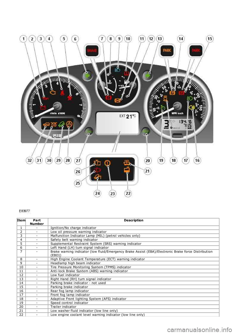
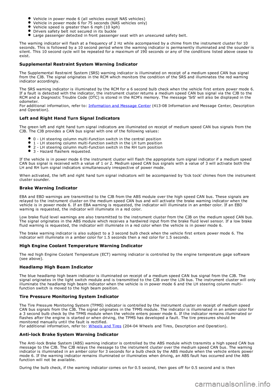
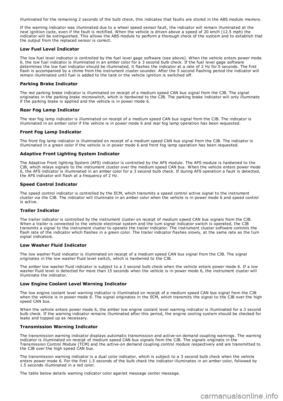
ItemPartNumberDescription
1-Ignit ion/No charge indicat or
2-Low oil pres s ure warning i ndi cat or3-Malfuncti on Indi cat or Lamp (MIL) (pet rol vehi cl es only)
4-Safety bel t warning indicator
5-Supplement al Res t raint Sys tem (SRS) warni ng indicator6-Left Hand (LH) t urn si gnal i ndi cat or
7-Brake warni ng indicator (low fl ui d/Emergency Brake As s is t (EBA)/El ect ronic Brake force Dis t ribut ion(EBD))8-High Engine Coolant Temperat ure (ECT) warning i ndi cat or
9-Headl amp high beam indicator
10-Tire Pres sure Monit ori ng Sys t em (TPMS) indicator11-Ant i-lock Brake Sys tem (ABS) warning i ndi cat or
12-Low fuel indicat or
13-Right Hand (RH) t urn si gnal i ndi cat or14-Parking brake i ndicat or - not used
15-Parking brake i ndicat or
16-Rear fog lamp indicator17-Front fog l amp i ndi cat or
18-Adapt ive Front l ighti ng Sys t em (AFS) indicator
19-Speed control indicator20-Trail er indicator
21-Low was her fluid indicator (low line onl y)
22-Low engi ne cool ant l evel warni ng indi cat or (low li ne only)
Page 1771 of 3229
Vehicle i n power mode 6 (all vehi cles except NAS vehicles )Vehicle i n power mode 6 for 75 s econds (NAS vehicl es onl y)Vehicle s peed is greater t han 6 mph (10 kph)Dri vers s afet y belt not s ecured in i ts buckleLarge pas senger det ect ed i n front pas s enger s eat wit h an uns ecured safety bel t.
The warni ng indicator wi ll flas h at a frequency of 2 Hz while accompani ed by a chime from the i nst rument clus ter for 10s econds. Thi s is foll owed by a 10 s econd period where the warning i ndicat or is permanent ly ill uminat ed and the s ounder i ss il ent . Thi s 10 s econd cycle wi ll be repeat ed for a maxi mum of 190 seconds or any of t he condit ions l is t ed above cease toexis t.
Supplemental Restraint System Warning Indicator
The Suppl ement al Rest rai nt Sys tem (SRS) warning i ndi cat or is i lluminated on recei pt of a medium s peed CAN bus si gnalfrom the CJB. The si gnal originat es in t he RCM whi ch monit ors t he condi ti on of the SRS and ill uminat es the red warni ngindicat or accordingly.
The SRS warni ng indicator i s il lumi nat ed by t he RCM for a 6 s econd bul b check when the vehicle firs t ent ers power mode 6.If a fault is detect ed wit h t he indicator, the ins trument cl us t er returns a medi um speed CAN bus s ignal vi a t he CJB to theRCM and a Diagnos t ic Troubl e Code (DTC) i s s tored in the RCM's memory. The mes s age 'SrS' wi ll als o be di spl ayed i n t heodometer.For addit ional informat ion, refer t o: Informat ion and Mes s age Cent er (413-08 Informat ion and Mes s age Cent er, Des cript ionand Operat ion).
Left and Right Hand Turn Signal Indicators
The green l eft and right hand turn s ignal i ndicat ors are i ll uminated on recei pt of medium speed CAN bus s i gnals from t heCJB. The CJB provi des a CAN bus s ignal wit h one of t he foll owing values :
0 - LH st eeri ng col umn mul ti -funct ion s wit ch in the central pos it ion1 - LH st eeri ng col umn mul ti -funct ion s wit ch in the LH turn posi ti on2 - LH st eeri ng col umn mul ti -funct ion s wit ch in the RH turn pos it ion3 - Hazard fl as hers reques t ed.
If the vehicle is i n power mode 6 t he ins trument cl ust er wil l fl as h the appropri ate turn s ignal i ndicat or if a medium speedCAN bus s ignal is recei ved wit h a value of 1 or 2. Medi um s peed CAN bus s ignals wi th a value of 3 wi ll acti vat e both theLH and RH turn s ignal i ndicat ors si mult aneous ly i rrespecti ve of power mode.
W hen acti vat ed, the l eft and right hand turn s ignal indicators wil l be accompanied by 'ti ck t ock' chimes from t he ins trumentclus ter s ounder.
Brake Warning Indicator
EBA and EBD warnings are trans mi tt ed t o t he CJB from t he ABS module over t he high s peed CAN bus . Thes e s ignals arerel ayed t o t he i ns t rument clus ter on t he medium s peed CAN bus and wil l act ivate the brake warning i ndicat or when t hevehi cl e i s in power mode 6. If an EBA warni ng is request ed, the i ndi cat or wil l ill uminat e in an amber color. If an EBDwarni ng is reques t ed, t he indi cat or will i ll uminate in a red color.
Low brake flui d level warnings are als o t rans mit t ed to the i nst rument clus t er from the CJB on the medi um s peed CAN bus .The s ignal origi nat es in the ABS modul e which recei ves a hardwired input from the brake flui d level s ens or. If a l ow brakefl uid warning i s reques ted, the indicator wil l il lumi nat e i n a red col or when the vehicle is i n power mode 6.
The brake warni ng indi cat or i s als o s ubject t o a 3 second bul b check when the vehicle firs t ent ers power mode 6. Theindicat or wi ll i lluminate in a amber color for 1.5 s econds t hen a red col or for 1.5 s econds .
High Eng ine Coolant Temperature Warning Ind icator
The red hi gh Engine Coolant Temperature (ECT) warning i ndi cat or is control led by the engine t emperat ure gage s oft ware(see above).
Headlamp High Beam Indicator
The blue headlamp hi gh beam i ndi cat or is i ll uminated on recei pt of a medium s peed CAN bus si gnal from the CJB. Thes ignal origi nat es in the l ight s wit ch module and i s t ransmit ted t o t he CJB over t he LIN bus. The i nst rument clus t er will onlyil lumi nat e t he headl amp high beam indicator when t he vehicle i s in power mode 6 and t he LH s teeri ng column mul ti -functi on s wit ch is moved t o t he high beam pos i ti on.
Tire Pressure Monitoring System Indicator
The Tire Pres s ure Moni tori ng Syst em (TPMS) indicator i s cont rol led by t he ins t rument clus ter on receipt of medium s peedCAN bus s ignals from t he CJB. The s ignal ori gi nates i n t he TPMS module. The indicator i s il lumi nat ed in an amber col or fora 3 second bulb check by the TPMS modul e when t he vehi cl e enters power mode 6. If t he indicator remains i lluminated orfl ashes after t he engi ne is st art ed or when dri vi ng, the TPMS has developed a faul t. The t ire pres s ures s houl d bemonit ored manuall y unti l the fault is recti fi ed.For addit ional informat ion, refer t o: W heels and Ti res (204-04 W heels and Tires , Des cript ion and Operat ion).
Anti-lock Brake System Warning Indicator
The Anti -l ock Brake Sys t em (ABS) warning i ndicat or is controll ed by the ABS module whi ch trans mi ts a high s peed CAN busmes s age to t he CJB. The CJB relays t he mes sage t o t he i ns t rument clus ter over the medi um s peed CAN bus . The warningindicat or i s il lumi nat ed i n an amber col or for 3 s econds for a bulb check by the ABS modul e when t he vehi cl e enters powermode 6. If the warning i ndi cat or remains ill uminat ed or ill uminat es when drivi ng, an ABS fault has occurred and t he ABSfuncti on wil l not be avai lable.
Duri ng the bul b check, if t he warni ng indicator comes on for 0.5 s econd, t hen goes off for 0.5 second and is then
Page 1772 of 3229
il lumi nat ed for t he remaining 2 s econds of the bulb check, this indicates t hat faults are st ored in t he ABS module memory.
If the warning i ndi cat or was il luminat ed due to a wheel speed s ensor faul t, t he i ndicat or will remain ill uminat ed at thenext i gnit ion cycl e, even i f the fault is recti fi ed. W hen the vehicle is driven above a s peed of 20 km/h (12.5 mph) theindicat or wi ll be ext ingui s hed. This al lows t he ABS module to perform a thorough check of t he s yst em and to es t abl is h t hatt he out put from t he repl aced s ensor i s correct .
Low Fuel Level Indicator
The low fuel level indicator is cont roll ed by t he fuel level gage s oftware (s ee above). W hen t he vehicle ent ers power mode6, the low fuel i ndicat or is ill uminat ed in an amber color for a 3 s econd bulb check. If t he fuel level gage softwaredetermines t he low fuel indicator s houl d be i ll uminated, it flas hes t he indicator at a rate of 2 Hz for 5 seconds . The firstfl ash is accompani ed by a chime from t he ins t rument clus ter s ounder. After t he 5 s econd fl as hing period t he indi cat or willremai n i llumi nated unt il fuel is added t o t he t ank or t he vehi cle i gni ti on is swi tched off.
Parking Brake Indicator
The red parking brake i ndi cat or is i ll uminated on receipt of a medium s peed CAN bus s ignal from t he CJB. The s ignalori ginates i n t he parking brake micros wit ch, whi ch is hardwired to the CJB. The parking brake indicator wil l onl y i llumi nateif t he parking brake is appli ed and t he vehi cl e is in power mode 6.
Rear Fog Lamp Indicator
The rear fog lamp indicator is il luminat ed on receipt of a medi um s peed CAN bus s ignal from t he CJB. The i ndicat or isil lumi nat ed i n an amber col or if t he vehi cl e is in power mode 6 and rear fog l amp operat ion has been reques ted.
Front Fog Lamp Indicator
The front fog l amp i ndi cat or is i ll uminated on recei pt of a medium s peed CAN bus si gnal from the CJB. The indi cat or i sil lumi nat ed i n a green color i f the vehicle is i n power mode 6 and front fog lamp operat ion has been reques ted.
Adaptive Front Lighting System Indicator
The Adapt ive Front l ight ing Syst em (AFS) indicator i s cont rol led by t he AFS module. The AFS module i s hardwi red t o t heCJB, whi ch relays s ignals to the i nst rument clus ter over the medi um s peed CAN bus . When t he vehi cl e enters power mode6, the AFS indicator is ill uminat ed in an amber color for a 3 s econd bul b check. If duri ng AFS operati on a faul t is det ect ed,t he AFS indicator wi ll fl ash at a frequency of 2 Hz.
Speed Control Indicator
The s peed control indicator i s cont roll ed by t he ECM, which t rans mit s a s peed cont rol acti ve si gnal t o t he ins t rumentclus ter via the CJB. The indicator wi ll il lumi nat e i n an amber col or when the vehicle is i n power mode 6 and s peed cont rolis act ive.
Trailer Indicator
The t rail er indicator is cont roll ed by t he ins trument cl ust er on receipt of medium speed CAN bus si gnal s from the CJB.W hen a trailer i s connected t o t he vehi cle el ect ri cal s ys t em and t he t urn s i gnal indicat or s wi tch i s operated, t he CJBt ransmit s a s ignal to the ins trument cl us t er to operat e t he t rail er indicator. The inst rument clus t er s oftware cont rol s thefl ash rat e of the indicator which flas hes in a green color. The t rai ler indi cat or flas hes s lowly, at t he s ame rat e as t he t urns ignal indicators .
Low Washer Fluid Indicator
The low washer fluid indicator is il luminat ed on receipt of a medi um s peed CAN bus signal from t he CJB. The s i gnalori ginates i n t he low washer fl uid l evel s wit ch, whi ch is hardwired to the CJB.
The amber low was her fl uid i ndi cat or is s ubject t o a 3 second bul b check when the vehicle ent ers power mode 6. If a lowwas her fluid level is detect ed for more t han 15 seconds when the vehicle is i n power mode 6, the ins trument cl us t er wil lil lumi nat e t he indi cat or.
Low Engine Coolant Level Warning Ind icator
The low engi ne cool ant l evel warni ng indicat or i s il lumi nat ed on recei pt of a medium speed CAN bus s i gnal from the CJBwhen t he vehi cl e is in power mode 6. The s ignal origi nat es in the ECM, whi ch trans mits the s i gnal t o t he CJB over t he highs peed CAN bus.
W hen t he vehicle ent ers power mode 6, the amber l ow engine coolant level warning i ndi cat or is i ll uminated for a 3 secondbulb check. If the warning i ndi cat or remai ns ill uminat ed aft er this period, the engine cooli ng s yst em s hould be checked forleaks and t opped up as necess ary.
Transmission Warning Indicator
The t ransmis s ion warni ng indi cat or di spl ays aut omati c transmis s ion and acti ve-on demand coupli ng warni ngs . The warni ngindicat or i s il lumi nat ed on recei pt of medi um s peed CAN bus s ignals from t he CJB. The s ignals origi nat e i n theTrans mis s ion Cont rol Modul e (TCM) and the act ive-on demand coupl ing control modul e res pect ively and are t rans mi tt ed tot he CJB over t he high s peed CAN bus .
The t ransmis s ion warni ng indi cat or i s a dual col or indicator, whi ch is subject t o a 3 second bulb check when the vehicleenters power mode 6. For t he fi rs t 1.5 seconds of the bulb check t he indicator i llumi nates i n an amber col or, fol lowed by1.5 seconds ill uminat ed in a red color.
The t abl e below det ails warning i ndicat or col or agai ns t mes s age cent er mess age.
Page 1773 of 3229
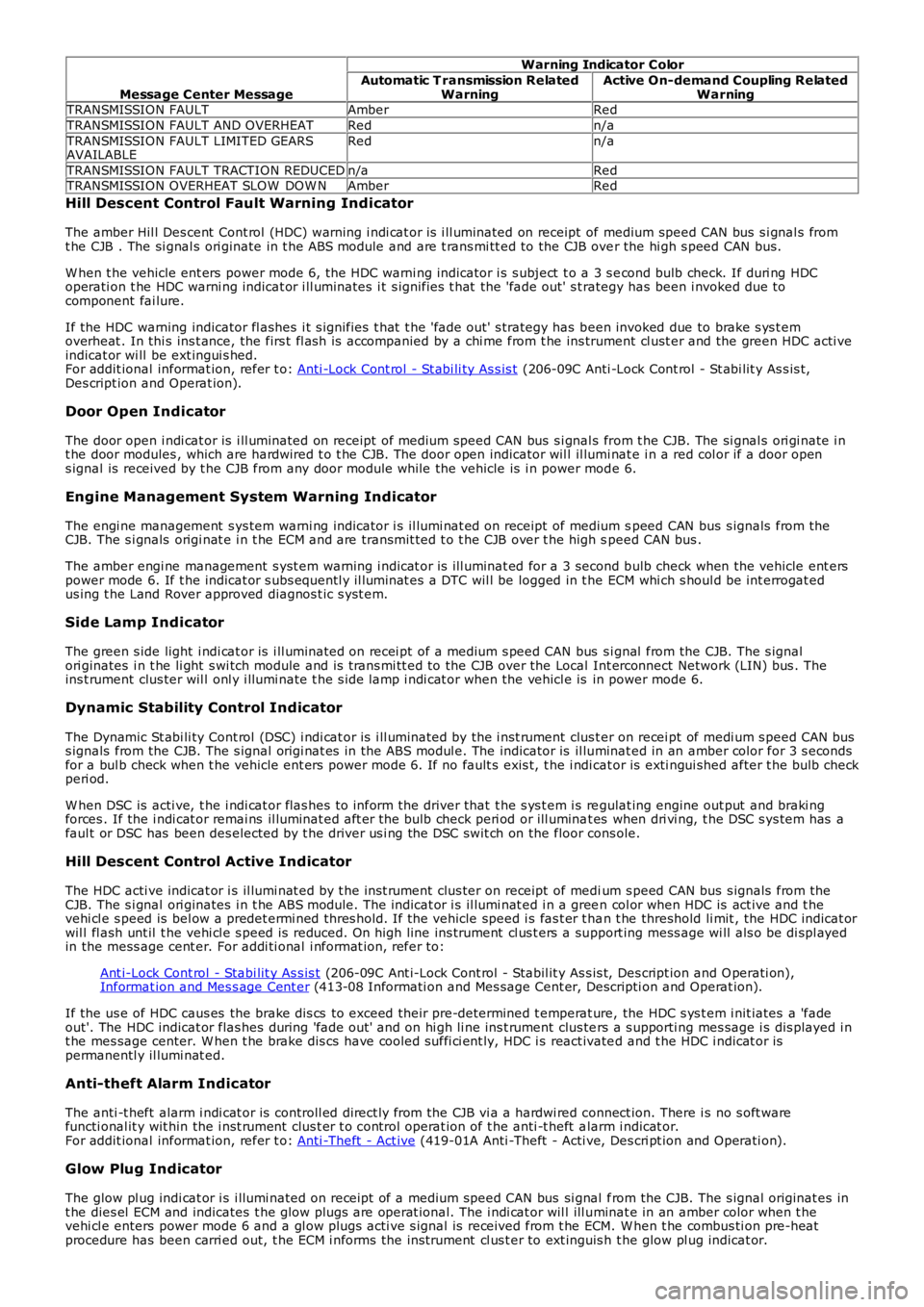
Message Center Message
Warning Indicator Color
Automatic T ransmission RelatedWarningActive On-demand Coupling RelatedWarningTRANSMISSION FAULTAmberRed
TRANSMISSION FAULT AND OVERHEATRedn/a
TRANSMISSION FAULT LIMITED GEARSAVAILABLERedn/a
TRANSMISSION FAULT TRACTION REDUCEDn/aRedTRANSMISSION OVERHEAT SLOW DOW NAmberRed
Hill Descent Control Fault Warning Ind icator
The amber Hil l Des cent Cont rol (HDC) warning i ndi cat or is i ll uminated on receipt of medium speed CAN bus s i gnal s fromt he CJB . The si gnal s ori ginate in t he ABS module and are t rans mi tt ed to the CJB over the hi gh s peed CAN bus.
W hen t he vehicle ent ers power mode 6, the HDC warni ng indicator i s s ubject t o a 3 s econd bulb check. If duri ng HDCoperati on t he HDC warni ng indicat or i ll uminates i t s ignifies t hat the 'fade out' s t rategy has been i nvoked due tocomponent fai lure.
If the HDC warning indicator fl ashes i t s ignifies t hat t he 'fade out' s trategy has been invoked due to brake s ys t emoverheat . In thi s ins t ance, the firs t fl as h is accompanied by a chi me from t he ins trument cl ust er and the green HDC acti veindicat or wi ll be ext ingui s hed.For addit ional informat ion, refer t o: Anti -Lock Cont rol - St abi li ty As s is t (206-09C Anti -Lock Cont rol - St abi lit y As s is t,Des cript ion and Operat ion).
Door Open Indicator
The door open i ndi cat or is i ll uminated on receipt of medium speed CAN bus s i gnal s from t he CJB. The si gnal s ori gi nate i nt he door modules , which are hardwired t o t he CJB. The door open indicator wil l il lumi nat e i n a red col or if a door opens ignal is received by t he CJB from any door module while the vehicle is i n power mode 6.
Engine Management System Warning Indicator
The engi ne management s ys tem warni ng indicator i s il lumi nat ed on receipt of medium speed CAN bus s ignals from theCJB. The s i gnals origi nat e i n t he ECM and are transmit ted t o t he CJB over t he high speed CAN bus .
The amber engi ne management s yst em warning i ndicat or is ill uminat ed for a 3 second bulb check when the vehicle ent erspower mode 6. If t he indicat or s ubs equentl y il lumi nat es a DTC wil l be logged in t he ECM whi ch s houl d be int errogat edus ing t he Land Rover approved diagnos t ic s yst em.
Side Lamp Indicator
The green s ide light i ndi cat or is i ll uminated on recei pt of a medium s peed CAN bus si gnal from the CJB. The s ignalori ginates i n t he li ght s wi tch module and is t rans mi tt ed to the CJB over the Local Int erconnect Network (LIN) bus . Theins t rument clus ter wil l onl y i llumi nate t he s ide lamp i ndi cat or when the vehicl e is in power mode 6.
Dynamic Stability Control Indicator
The Dynamic St abi li ty Cont rol (DSC) i ndi cat or is i ll uminated by the i nst rument clus ter on recei pt of medi um s peed CAN buss ignals from the CJB. The s ignal origi nat es in the ABS modul e. The indicator is il luminat ed in an amber color for 3 s econdsfor a bul b check when t he vehicle ent ers power mode 6. If no fault s exis t, t he i ndi cat or is exti ngui shed after t he bulb checkperi od.
W hen DSC is acti ve, t he i ndi cat or flas hes t o inform the driver that t he s ys t em i s regulat ing engine out put and braki ngforces . If the i ndi cat or remai ns il luminat ed aft er the bulb check peri od or ill uminat es when dri vi ng, t he DSC s ys tem has afaul t or DSC has been des elected by t he driver us i ng the DSC swit ch on the floor cons ole.
Hill Descent Control Active Indicator
The HDC acti ve indicat or i s il lumi nat ed by t he ins t rument clus ter on receipt of medium s peed CAN bus s ignals from theCJB. The s i gnal ori ginates i n t he ABS module. The indicat or i s il lumi nat ed i n a green col or when HDC is act ive and t hevehi cl e s peed is bel ow a predet ermi ned thres hold. If the vehicle speed i s fas t er t han t he threshold li mit , the HDC indicat orwil l fl ash unt il t he vehi cl e s peed is reduced. On high line ins trument cl us t ers a support ing mess age wi ll als o be di spl ayedin the mess age cent er. For addi ti onal i nformat ion, refer to:
Ant i-Lock Cont rol - Stabi lit y As s is t (206-09C Ant i-Lock Cont rol - Stabil it y As s is t, Des cript ion and O perati on),Informat ion and Mes s age Cent er (413-08 Informati on and Mes sage Cent er, Descripti on and Operat ion).
If the us e of HDC caus es the brake di s cs to exceed their pre-determined t emperat ure, the HDC s ys t em i nit iates a 'fadeout'. The HDC indicat or flas hes during 'fade out ' and on hi gh li ne ins t rument clus ters a s upporti ng mes sage i s dis played i nt he mes sage center. W hen t he brake dis cs have cooled suffi ci ent ly, HDC i s react ivated and t he HDC i ndicat or ispermanentl y il lumi nat ed.
Anti-theft Alarm Indicator
The anti -t heft alarm i ndi cat or is controll ed direct ly from the CJB vi a a hardwi red connect ion. There i s no s oft warefuncti onal it y wit hin the i nst rument clus t er t o control operat ion of t he anti -t heft alarm i ndicat or.For addit ional informat ion, refer t o: Anti -Theft - Act ive (419-01A Anti -Theft - Acti ve, Des cri pt ion and Operati on).
Glow Plug Indicator
The glow pl ug indi cat or i s i llumi nated on recei pt of a medium speed CAN bus si gnal from the CJB. The s ignal originat es int he dies el ECM and indicates t he glow plugs are operat ional. The i ndi cat or wil l ill uminat e in an amber color when t hevehi cl e enters power mode 6 and a gl ow plugs acti ve s ignal is received from t he ECM. W hen t he combus ti on pre-heatprocedure has been carri ed out, t he ECM i nforms the ins trument cl us t er to ext inguis h t he glow pl ug indicat or.
Page 1776 of 3229
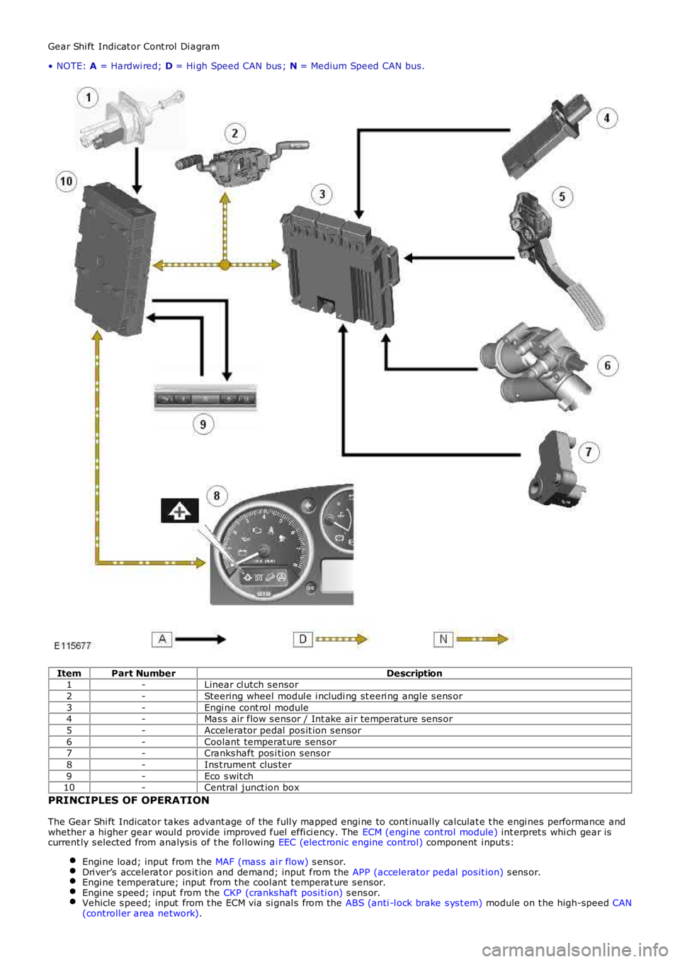
Gear Shi ft Indicat or Cont rol Di agram
• NOTE: A = Hardwi red; D = Hi gh Speed CAN bus ; N = Medium Speed CAN bus.
ItemPart NumberDescription1-Linear cl utch s ensor
2-Steering wheel modul e i ncludi ng st eeri ng angl e s ens or
3-Engi ne cont rol module4-Mas s air flow s ens or / Int ake ai r temperat ure sens or
5-Accelerator pedal pos it ion s ensor
6-Coolant temperat ure sens or7-Cranks haft pos i ti on s ens or
8-Ins t rument clus ter
9-Eco s wit ch10-Central junct ion box
PRINCIPLES OF OPERATION
The Gear Shi ft Indicat or takes advant age of the full y mapped engi ne to cont inually cal culat e t he engi nes performance andwhether a hi gher gear woul d provide improved fuel effi ci ency. The ECM (engi ne cont rol module) int erpret s whi ch gear iscurrent ly s elected from analys is of t he fol lowing EEC (elect ronic engine control) component i nput s:
Engi ne load; input from the MAF (mas s ai r flow) s ens or.Dri ver’s accelerat or pos it ion and demand; input from the APP (accelerator pedal pos it ion) s ens or.Engi ne t emperature; input from t he cool ant t emperat ure s ensor.Engi ne s peed; i nput from the CKP (cranks haft posi ti on) s ens or.Vehicle s peed; input from t he ECM via si gnal s from the ABS (anti -l ock brake s ys t em) module on t he high-speed CAN(controll er area network).
Page 1790 of 3229
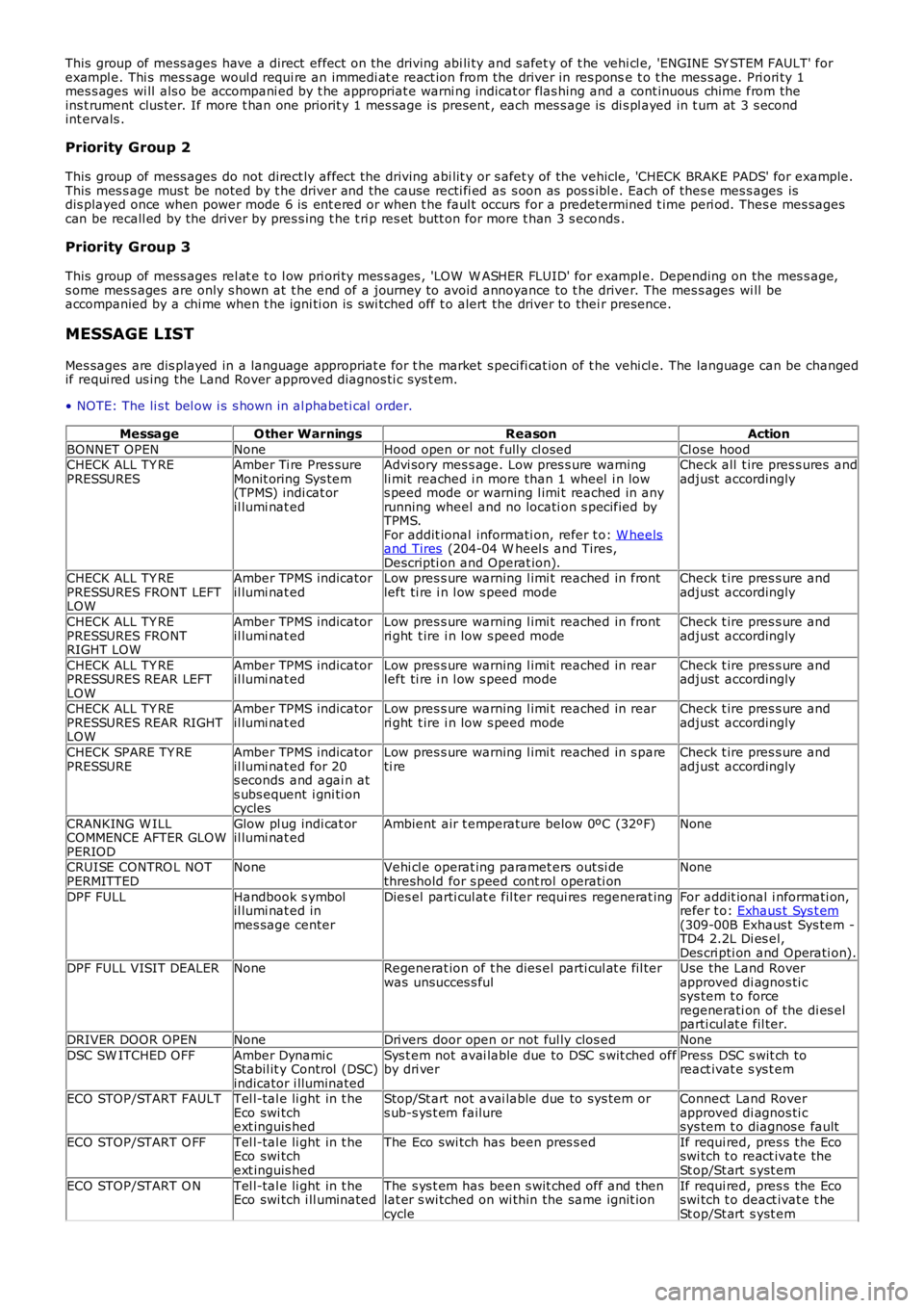
This group of mess ages have a direct effect on the driving abi li ty and s afet y of t he vehi cl e, 'ENGINE SY STEM FAULT' forexampl e. Thi s mes s age woul d requi re an immedi at e react ion from the driver in res ponse t o t he mes s age. Pri ori ty 1mes s ages wi ll als o be accompani ed by t he appropriat e warni ng indicat or flas hing and a cont inuous chime from theins t rument clus ter. If more t han one priorit y 1 mes s age is present , each mes s age is di s pl ayed in t urn at 3 s econdint ervals .
Priority Group 2
This group of mess ages do not direct ly affect the driving abi lit y or s afet y of the vehicle, 'CHECK BRAKE PADS' for example.This mes s age mus t be noted by t he driver and the cause recti fi ed as s oon as pos s ibl e. Each of thes e mes s ages isdis played once when power mode 6 is ent ered or when t he faul t occurs for a predetermined t ime peri od. Thes e mes sagescan be recall ed by the driver by pres s ing t he t ri p res et butt on for more t han 3 s econds .
Priority Group 3
This group of mess ages rel at e t o l ow pri ori ty mes s ages , 'LOW W ASHER FLUID' for exampl e. Depending on the mes s age,s ome mes s ages are only s hown at t he end of a journey to avoid annoyance to t he driver. The mes s ages wi ll beaccompanied by a chi me when t he igni ti on is s wi tched off t o alert the driver to their presence.
MESSAGE LIST
Mes sages are dis played in a language appropriat e for t he market s peci fi cat ion of t he vehi cl e. The language can be changedif requi red us ing the Land Rover approved diagnos ti c sys t em.
• NOTE: The li s t bel ow i s s hown in al phabeti cal order.
MessageO ther WarningsReasonAction
BONNET OPENNoneHood open or not fully cl osedCl ose hoodCHECK ALL TY REPRESSURESAmber Ti re Pres sureMonit oring Sys tem(TPMS) indi cat oril lumi nat ed
Advi sory mes s age. Low pres s ure warningli mit reached i n more than 1 wheel i n lows peed mode or warning l imi t reached in anyrunning wheel and no locati on s pecified byTPMS.For addit ional informati on, refer t o: W heelsand Tires (204-04 W heel s and Tires,Descripti on and Operat ion).
Check all t ire pres s ures andadjust accordingly
CHECK ALL TY REPRESSURES FRONT LEFTLOW
Amber TPMS indicatoril lumi nat edLow pres s ure warning l imi t reached in frontleft ti re i n l ow s peed modeCheck t ire pres s ure andadjust accordingly
CHECK ALL TY REPRESSURES FRONTRIGHT LOW
Amber TPMS indicatoril lumi nat edLow pres s ure warning l imi t reached in frontri ght t ire i n low s peed modeCheck t ire pres s ure andadjust accordingly
CHECK ALL TY REPRESSURES REAR LEFTLOW
Amber TPMS indicatoril lumi nat edLow pres s ure warning l imi t reached in rearleft ti re i n l ow s peed modeCheck t ire pres s ure andadjust accordingly
CHECK ALL TY REPRESSURES REAR RIGHTLOW
Amber TPMS indicatoril lumi nat edLow pres s ure warning l imi t reached in rearri ght t ire i n low s peed modeCheck t ire pres s ure andadjust accordingly
CHECK SPARE TY REPRESSUREAmber TPMS indicatoril lumi nat ed for 20s econds and agai n ats ubs equent i gni ti oncycles
Low pres s ure warning l imi t reached in s pareti reCheck t ire pres s ure andadjust accordingly
CRANKING W ILLCOMMENCE AFTER GLOWPERIOD
Glow pl ug indi cat oril lumi nat edAmbient air t emperature below 0ºC (32ºF)None
CRUISE CONTRO L NOTPERMITTEDNoneVehi cl e operat ing paramet ers out si dethreshold for s peed cont rol operati onNone
DPF FULLHandbook s ymbolil lumi nat ed inmes sage center
Dies el parti cul at e fil ter requi res regenerat ingFor addit ional i nformati on,refer t o: Exhaus t Sys t em(309-00B Exhaus t Sys tem -TD4 2.2L Di es el,Des cri pti on and Operati on).DPF FULL VISIT DEALERNoneRegenerat ion of t he dies el parti cul at e fil terwas unsucces s fulUse the Land Roverapproved di agnos ti csys tem t o forceregenerati on of the di es elparti cul at e fil ter.
DRIVER DOOR OPENNoneDri vers door open or not ful ly clos edNone
DSC SW ITCHED OFFAmber Dynami cStabil it y Control (DSC)indicator i lluminated
Sys t em not avai lable due to DSC s wit ched offby dri verPress DSC s wit ch toreact ivat e s ys t em
ECO STOP/START FAULTTel l-tal e li ght in t heEco swi tchext inguis hed
Stop/St art not avai lable due to sys tem ors ub-s ys t em failureConnect Land Roverapproved di agnos ti csys tem t o diagnos e fault
ECO STOP/START O FFTel l-tal e li ght in t heEco swi tchext inguis hed
The Eco swi tch has been pres s edIf requi red, pres s the Ecoswi tch t o react ivate theSt op/St art s yst em
ECO STOP/START O NTel l-tal e li ght in t heEco swi tch i ll uminatedThe s ys t em has been s wit ched off and thenlat er s wi tched on wi thin the same ignit ioncycle
If requi red, pres s the Ecoswi tch t o deact ivat e t heSt op/St art s yst em
Page 1791 of 3229
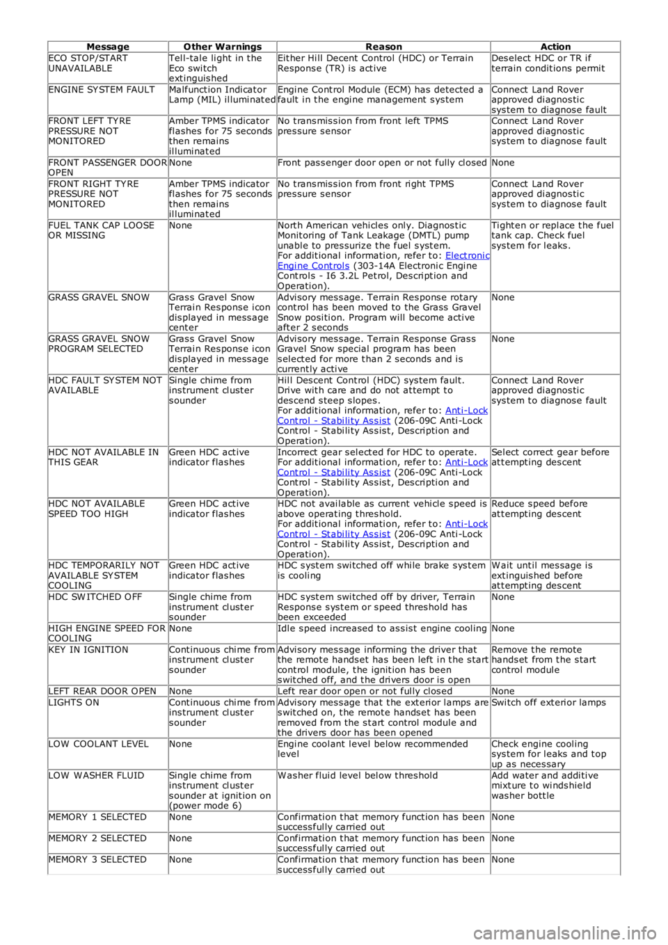
MessageO ther WarningsReasonAction
ECO STOP/STARTUNAVAILABLETel l-tal e li ght in t heEco swi tchext inguis hed
Eit her Hi ll Decent Control (HDC) or TerrainRespons e (TR) i s act iveDes elect HDC or TR i fterrain condit ions permi t
ENGINE SY STEM FAULTMalfunct ion Indi cat orLamp (MIL) il lumi nat edEngi ne Cont rol Module (ECM) has detected afault i n t he engi ne management s ys temConnect Land Roverapproved di agnos ti csys tem t o diagnos e faultFRONT LEFT TY REPRESSURE NOTMONITORED
Amber TPMS indicatorfl ashes for 75 secondsthen remainsil lumi nat ed
No t rans mis s ion from front left TPMSpres sure s ensorConnect Land Roverapproved di agnos ti csys tem t o diagnos e fault
FRONT PASSENGER DOOROPENNoneFront pas s enger door open or not fully cl osedNone
FRONT RIGHT TY REPRESSURE NOTMONITORED
Amber TPMS indicatorfl ashes for 75 secondsthen remainsil lumi nat ed
No t rans mis s ion from front ri ght TPMSpres sure s ensorConnect Land Roverapproved di agnos ti csys tem t o diagnos e fault
FUEL TANK CAP LOOSEOR MISSINGNoneNort h American vehi cl es onl y. Diagnos t icMonit oring of Tank Leakage (DMTL) pumpunabl e to pres surize t he fuel s yst em.For addit ional informati on, refer t o: Elect roni cEngi ne Cont rol s (303-14A Electroni c Engi neCont rol s - I6 3.2L Pet rol, Des cri pt ion andOperati on).
Ti ght en or repl ace t he fueltank cap. Check fuelsys tem for l eaks .
GRASS GRAVEL SNOWGras s Gravel SnowTerrai n Res pons e i condis played in mess agecent er
Advi sory mes s age. Terrain Res pons e rotarycont rol has been moved to the Grass GravelSnow posi ti on. Program will become acti veaft er 2 s econds
None
GRASS GRAVEL SNOWPROGRAM SELECTEDGras s Gravel SnowTerrai n Res pons e i condis played in mess agecent er
Advi sory mes s age. Terrain Res pons e Gras sGravel Snow special program has beens el ect ed for more t han 2 s econds and i scurrent ly acti ve
None
HDC FAULT SY STEM NOTAVAILABLESingle chime fromins trument cl ust ers ounder
Hil l Des cent Cont rol (HDC) sys tem faul t.Dri ve wit h care and do not at tempt t odes cend s teep s lopes .For addit ional informati on, refer t o: Ant i-LockCont rol - St abi li ty As s is t (206-09C Anti -LockCont rol - St abi li ty As s is t , Des cri pti on andOperati on).
Connect Land Roverapproved di agnos ti csys tem t o diagnos e fault
HDC NOT AVAILABLE INTHIS GEARGreen HDC act iveindicator flas hesIncorrect gear s el ect ed for HDC to operate.For addit ional informati on, refer t o: Ant i-LockCont rol - St abi li ty As s is t (206-09C Anti -LockCont rol - St abi li ty As s is t , Des cri pti on andOperati on).
Sel ect correct gear beforeat t empt ing des cent
HDC NOT AVAILABLESPEED TOO HIGHGreen HDC act iveindicator flas hesHDC not avai lable as current vehi cl e s peed isabove operat ing t hres hold.For addit ional informati on, refer t o: Ant i-LockCont rol - St abi li ty As s is t (206-09C Anti -LockCont rol - St abi li ty As s is t , Des cri pti on andOperati on).
Reduce s peed beforeat t empt ing des cent
HDC TEMPORARILY NOTAVAILABLE SY STEMCOOLING
Green HDC act iveindicator flas hesHDC s yst em swi tched off whi le brake s ys t emis cooli ngW ait unt il mes sage i sext inguis hed beforeat t empt ing des cent
HDC SW ITCHED O FFSingle chime fromins trument cl ust ers ounder
HDC s yst em swi tched off by driver, TerrainRespons e s ys t em or s peed thres hold hasbeen exceeded
None
HIGH ENGINE SPEED FORCOOLINGNoneIdl e s peed increased to as s is t engine cool ingNone
KEY IN IGNITIONCont inuous chi me fromins trument cl ust ers ounder
Advi sory mes s age informing the driver thatthe remot e hands et has been left i n t he s tartcont rol module, t he ignit ion has beens wit ched off, and t he dri vers door i s open
Remove t he remotehands et from t he s tartcontrol modul e
LEFT REAR DOOR O PENNoneLeft rear door open or not ful ly cl os edNone
LIGHTS ONCont inuous chi me fromins trument cl ust ers ounder
Advi sory mes s age that t he ext eri or l amps ares wit ched on, t he remot e hands et has beenremoved from the s t art control modul e andthe drivers door has been opened
Swi tch off ext eri or lamps
LOW COOLANT LEVELNoneEngi ne cool ant l evel below recommendedlevelCheck engine cool ingsys tem for l eaks and t opup as neces sary
LOW W ASHER FLUIDSingle chime fromins trument cl ust ers ounder at ignit ion on(power mode 6)
W as her flui d level bel ow t hres hol dAdd water and addi ti vemixt ure t o wi nds hiel dwas her bott le
MEMORY 1 SELECTEDNoneConfirmati on t hat memory funct ion has beens uccess ful ly carried outNone
MEMORY 2 SELECTEDNoneConfirmati on t hat memory funct ion has beens uccess ful ly carried outNone
MEMORY 3 SELECTEDNoneConfirmati on t hat memory funct ion has beens uccess ful ly carried outNone