2006 LAND ROVER FRELANDER 2 brake
[x] Cancel search: brakePage 1300 of 3229
Publi s hed: 11-May-2011
Automatic Transmission/Transaxle - Transmission Fluid Drain and RefillI6
3.2L Petrol
General Procedures W ARNING: Observe due care when drai ning, as the flui d can be very hot .
Ens ure t hat the aut omat ic trans mi s si on is in 'P' and t he handbrake is
ful ly appli ed.
1.
Remove t he air cleaner hous ing.
Refer t o: Air Cleaner (303-12B Intake Ai r Dis tribut ion and Fil tering -
TD4 2.2L Dies el, Removal and Inst all ati on).
2.
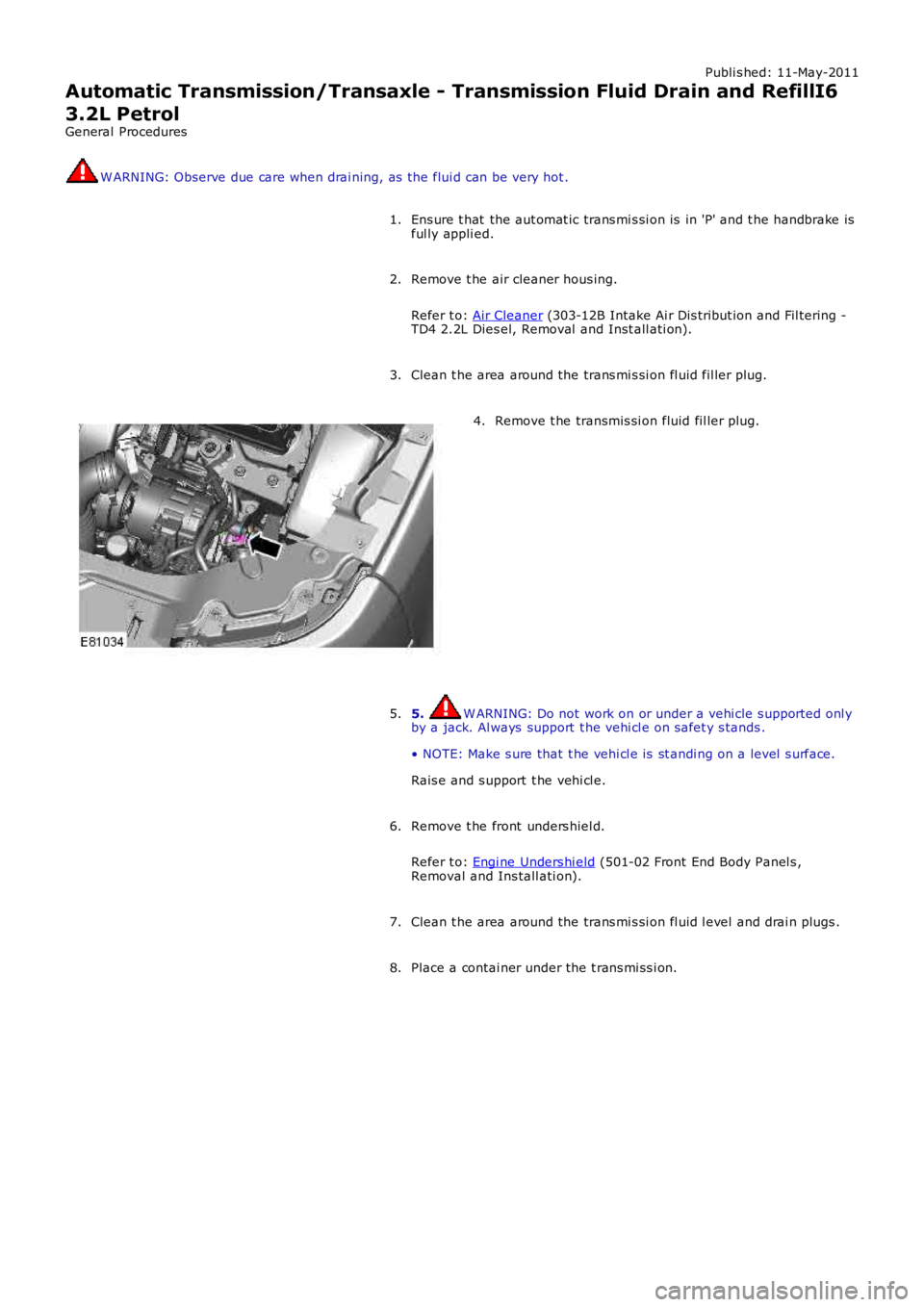
Clean t he area around the trans mi s si on fl uid fil ler plug.
3. Remove t he transmis si on fluid fil ler plug.
4.
5. W ARNING: Do not work on or under a vehi cle s upported onl y
by a jack. Al ways support t he vehi cl e on s afet y s tands .
• NOTE: Make s ure that t he vehi cl e is st andi ng on a level s urface.
Rais e and s upport t he vehi cl e.
5.
Remove t he front unders hiel d.
Refer t o: Engi ne Unders hi eld (501-02 Front End Body Panel s ,
Removal and Ins tall ati on).
6.
Clean t he area around the trans mi s si on fl uid l evel and drai n plugs .
7.
Place a contai ner under the t rans mi ss i on.
8.
Page 1303 of 3229
Publi s hed: 11-May-2011
Automatic Transmission/Transaxle - Transmission Fluid Level CheckTD4
2.2L Diesel
General Procedures W ARNING: Observe due care when drai ning, as the flui d can be very hot .
Ens ure t hat the aut omat ic trans mi s si on is in 'P' and t he handbrake is
ful ly appli ed.
1.
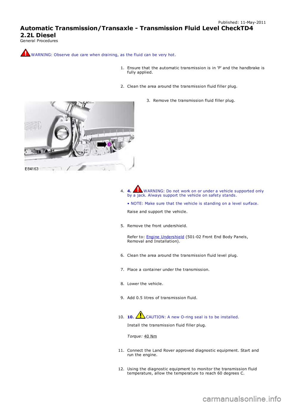
Clean t he area around the trans mi s si on fl uid fil ler plug.
2. Remove t he transmis si on fluid fil ler plug.
3.
4. W ARNING: Do not work on or under a vehi cle s upported onl y
by a jack. Al ways support t he vehi cl e on s afet y s tands .
• NOTE: Make s ure that t he vehi cl e is st andi ng on a level s urface.
Rais e and s upport t he vehi cl e.
4.
Remove t he front unders hiel d.
Refer t o: Engi ne Unders hi eld (501-02 Front End Body Panel s ,
Removal and Ins tall ati on).
5.
Clean t he area around the trans mi s si on fl uid l evel plug.
6.
Place a contai ner under the t rans mi ss i on.
7.
Lower the vehicle.
8.
Add 0.5 li tres of trans mi s si on fl uid.
9.
10. CAUTION: A new O-ring s eal is t o be ins tall ed.
Inst all t he transmis si on fluid fil ler plug.
T orque: 40 Nm 10.
Connect t he Land Rover approved diagnos t ic equipment. St art and
run the engine.
11.
Us ing t he diagnos ti c equi pment t o moni tor t he transmis s ion fluid
t emperature, al low the t emperat ure t o reach 60 degrees C.
12.
Page 1305 of 3229
Publi s hed: 11-May-2011
Automatic Transmission/Transaxle - Transmission Fluid Drain and RefillTD4
2.2L Diesel
General Procedures W ARNING: Observe due care when drai ning, as the flui d can be very hot .
Ens ure t hat the aut omat ic trans mi s si on is in 'P' and t he handbrake is
ful ly appli ed.
1.
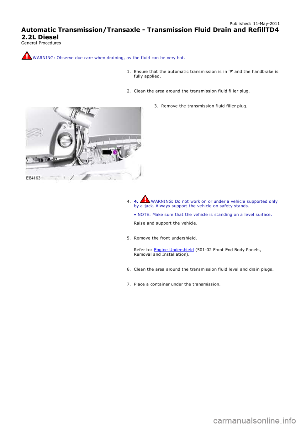
Clean t he area around the trans mi s si on fl uid fil ler plug.
2. Remove t he transmis si on fluid fil ler plug.
3.
4. W ARNING: Do not work on or under a vehi cle s upported onl y
by a jack. Al ways support t he vehi cl e on s afet y s tands .
• NOTE: Make s ure that t he vehi cl e is st andi ng on a level s urface.
Rais e and s upport t he vehi cl e.
4.
Remove t he front unders hiel d.
Refer t o: Engi ne Unders hi eld (501-02 Front End Body Panel s ,
Removal and Ins tall ati on).
5.
Clean t he area around the trans mi s si on fl uid l evel and drai n plugs .
6.
Place a contai ner under the t rans mi ss i on.
7.
Page 1371 of 3229
Circui t Board (PCB) and Hal l effect s ensors which detect t he s el ect ed posi ti on of the sel ect or lever (M/S and +/-) via amagnet locat ed on t he lever mechani sm. The si gnal s from t he Hall s ens ors are pas s ed from a connector on t he s ens ormodule t o t he TCM on a Local Int erconnect Network (LIN) bus .
The s ens or module main connect or us es four pins for LIN bus , ground, power and neutral inputs and out put s . A s econdconnector all ows for t he connecti on of a ri bbon cable from t he s elector posi ti on LED for ni ght i ll uminati on and posi ti onil lumi nat ion. A t hird connector s uppl ies power and ground connecti ons to the s hift int erl ock s olenoid.
The s ens or module al so includes an opti cal s ensor which det ermi nes that t he sel ect or lever i s i n the Park (P) pos it ion. Thes ens or is locat ed behind t he module hous ing and i s not vi s ible. Ali gnment marks on the s ens or housi ng and the sens orarm mus t be ali gned when the s elect or l ever i s in the Park (P) pos it ion. W hen t hes e 2 marks are ali gned the opt icals ens or/park pos it ion i s correct ly adjus t ed. This adjust ment is set at t he point of manufacture and does not requi rere-s et t ing under normal operati ng condit ions .
Sport/Manual +/- CommandShift™
The s ens or module contai ns the hal l effect s ens ors to act ivate the s port /manual mode and als o t he s ensors which provi det he +/- s i gnal s. W hen the s elect or l ever i s moved to the manual /s port pos it ion, the magnet located in t he s elector levermechani sm i s moved wit hin proxi mit y of t he M/S hall effect s ensor on t he PCB. This provi des t he s ignal which i s receivedby t he TCM, which in turn ini ti at es s port mode.
W hen t he l ever is moved to the + or - pos i ti on, t he magnet is moved wi thi n proximit y of one of the hall effect sens orsposi ti oned ei ther s ide of t he M/S hall effect s ens or. W hen an input from eit her the + or - s ens ors is recei ved, manualCommandShi ft ™ mode wil l be ini ti at ed. In this pos i ti on a s pri ng wil l move the s elector l ever back to the centre pos it ionwhen rel eas ed. To leave t he CommandShi ft ™ mode, return t he lever to the 'D' pos it ion.
Shift Interlock
The s hift interlock s ol enoi d i s located on t he LH s i de of the s elector l ever as sembly. The sol enoid operates t wo l ockinglevers whi ch engage wi th the lever mechanis m and lock it i n t he Park (P) and Neut ral (N) pos i ti ons . W hen t he i gni ti on isoff, the sol enoid is de-energized, l ocking the s elector l ever i n the Park (P) pos it ion. If the s elector l ever i s in any pos it ionother t han Park (P), t he remot e hands et cannot be removed from t he s tart cont rol module unt il t he lever is moved t o t hePark (P) posi ti on.
The s hift interlock s ol enoi d has a mechanical connect ion t o t he s ens or module us ing a s ens or arm. Movement of thes olenoi d i s transferred via t he s ensor arm t o t he s ens or module whi ch det ect s t he movement usi ng an opti cal s ensor. Thes ens or arm movement provides a confi rmat ion t o t he s ens or module t hat the sol enoid is i n i ts i nterlocked pos it ion. Thes ens or arm has a ratchet adjust ment for al ignment of t he opti cal s ensor and i s fact ory s et and mus t not be adjust ed.
The s hift interlock s ol enoi d l ocks t he s el ect or lever in t he park pos it ion or t he neutral pos it ion t o prevent inadvert ents elect ions on the s elector l ever. The interlock is releas ed when t he ignit ion i s on and t he dri ver pres s es t he brake pedal . As ignal from t he brake s wit ch is pas s ed on t he high s peed Cont rol ler Area Net work (CAN) bus t o t he TCM and i s thenpass ed on t he LIN bus t o the sens or modul e. On receipt of t hi s s ignal the s ens or modul e logic energi zes the s olenoid if i nt he Park (P) pos it ion or de-energizes the sol enoid if i n t he Neut ral (N) posi ti on, releas ing t he int erlock mechani s m.
If the s elector l ever is left in t he 'N' pos it ion for more t han 3 s econds , the sol enoi d wil l be energized and t he s el ect or leverwil l become locked i n t he 'N' posi ti on. To move the sel ect or lever from t he 'N' positi on in this condit ion, t he footbrake mus tbe applied. This prevent s the sel ect or lever from being moved t o t he 'D' or 'R' positi on unintent ionally and the appli cat ionof the brakes al s o prevent s t he vehi cle 'creepi ng' when t he gear is engaged. Movement of t he s elector lever from t he 'P' or'N' pos it ions is al s o prevent ed i f the TCM sens es t he engi ne s peed i s above 2500 rev/mi n, even i f the brake pedal isdepres sed.
If a fault occurs wi th the s hift int erl ock s olenoid, t he s ens or module, the brake s wit ch or as s oci ated wi ri ng, an emergencyrel eas e l ever i s provided t o dis connect t he int erlock mechani sm. The emergency releas e lever can be acces sed by us i ng at ool t o remove the s elector l ever t ri m finis her from t he floor cons ole. The fi nis her can be lifted to gai n acces s t o therel eas e l ever whi ch is l ocat ed at the front t he s elect or lever ass embly and is colored yel low for identi fi cat ion.
• NOTE: The s elector lever cannot be moved from the 'Park' pos it ion i f the ignit ion i s s wit ched off unl ess the emergencyrel eas e l ever i s us ed.
TRANSMISSION CABLE
Page 1372 of 3229
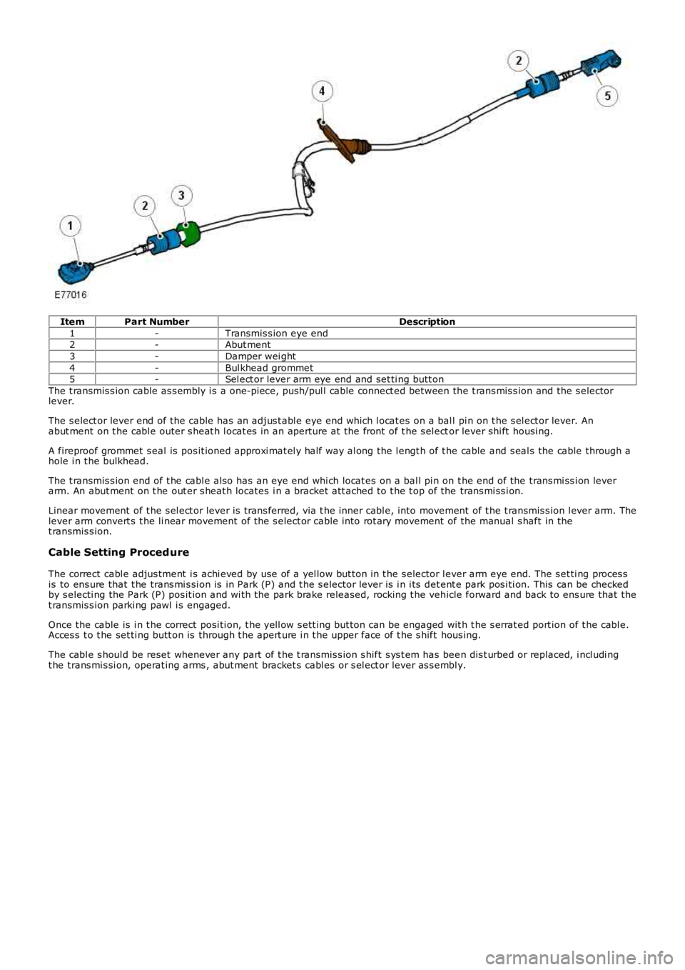
ItemPart NumberDescription
1-Transmis s ion eye end2-Abut ment
3-Damper wei ght
4-Bul khead grommet5-Sel ect or lever arm eye end and set ti ng butt on
The t ransmis s ion cable as s embly i s a one-pi ece, push/pul l cable connect ed between the t rans mis s ion and the s electorlever.
The s elect or lever end of the cable has an adjus t abl e eye end which l ocat es on a ball pi n on t he s el ect or lever. Anabut ment on t he cabl e outer s heat h l ocat es in an aperture at the front of t he s el ector lever shi ft housi ng.
A fireproof grommet s eal is pos it ioned approxi mat el y half way al ong the l engt h of t he cable and s eal s the cable through ahole i n t he bulkhead.
The t ransmis s ion end of t he cabl e als o has an eye end whi ch locat es on a bal l pi n on t he end of the trans mi ss i on leverarm. An abut ment on t he out er s heat h locates i n a bracket att ached to t he t op of the trans mi ss i on.
Linear movement of t he s el ect or lever is t rans ferred, via t he inner cabl e, into movement of t he t ransmis s ion l ever arm. Thelever arm convert s t he li near movement of the s elect or cable i nto rot ary movement of the manual s haft in thet ransmis s ion.
Cable Setting Proced ure
The correct cabl e adjus tment i s achi eved by use of a yel low but ton in t he s elector lever arm eye end. The s et ti ng proces sis to ens ure that t he trans mi s si on is in Park (P) and t he s elector lever is i n i ts det ent e park pos i ti on. This can be checkedby s electi ng the Park (P) pos it ion and wi th the park brake released, rocking t he vehicle forward and back to ens ure that thet ransmis s ion parki ng pawl i s engaged.
Once the cable is i n t he correct posi ti on, t he yell ow s ett ing but ton can be engaged wit h t he s errat ed port ion of t he cabl e.Acces s t o t he set ti ng butt on is through t he apert ure i n t he upper face of t he s hift hous ing.
The cabl e s houl d be reset whenever any part of t he t ransmis s ion s hift s ys t em has been dis t urbed or replaced, i ncl udi ngt he trans mi s si on, operat ing arms , abut ment bracket s cabl es or s el ect or lever as s embly.
Page 1400 of 3229
s ynchronizi ng hub towards the revers e gear i dler gear.
The coupl ing s leeve and s ynchronizi ng hub lock t he revers e gear idler gear at the revers e s haft.
The t orque of the engine is t rans ferred via the cl ut ch t o the input shaft. The 1s t gear on t he i nput s haft t rans fers power t ot he 1st gear idl er gear. The power is then t rans ferred t o t he revers e gear idl er gear and then t o t he reverse gear coupl ings leeve. From t here power is trans ferred to t he i nt ermedi ate s haft 1s t - 2nd and 5t h - 6th and to the final dri ve which i nt urn t rans fers power t o t he ring gear. The ring gear is connect ed to the drive s hafts t hrough the di fferenti al.
Differential
The different ial dis t ribut es dri ve from t he t ransmis s ion equally bet ween t he LH and RH front half s haft s and als o provi desdri ve torque to the rear di fferenti al vi a t he power t rans fer unit .
The different ial is locat ed at t he rear of the trans mi ss i on hous ing. Both s ides of the di fferenti al are connected to t he LHand RH drive s haft s, s upplying t orque t o t he front wheel s The different ial is als o connected t o t he Power Transfer Unit viaa s pli ned shaft to the RH s ide of t he trans mi s si on, s upplying t orque t o t he rear driveline.
Reverse Switch
The revers e s wi tch i s located i n t he front of the t rans mis s ion cas ing, above t he 1s t gear det ect ion s wi tch. The swi tch i sus ed by the Ant i-lock Brake Sys tem (ABS) module for Hil l Descent Cont rol (HDC) and als o for revers ing l amp operati on.
1st Gear Position Switch
The 1s t gear s wit ch is locat ed on t he front of the t rans mi ss ion cas ing, below t he reverse swit ch. The s wit ch is us ed by t heABS module for HDC.
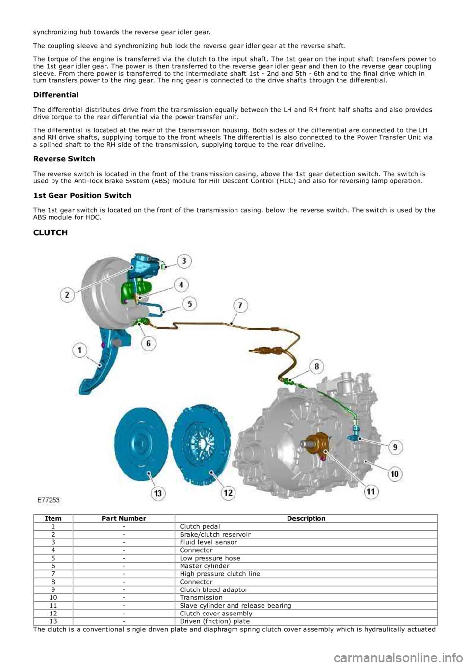
CLUTCH
ItemPart NumberDescription1-Clutch pedal
2-Brake/clut ch res ervoir
3-Fl uid l evel s ensor4-Connector
5-Low pres s ure hos e
6-Mast er cyl inder7-High pres s ure cl utch l ine
8-Connector
9-Clutch bl eed adapt or10-Transmis s ion
11-Slave cyl inder and releas e beari ng
12-Clutch cover as s embly13-Dri ven (fri ct ion) plat e
The clutch i s a convent ional si ngl e driven plat e and diaphragm spring clut ch cover ass embly which is hydraul ically act uat ed
Page 1404 of 3229
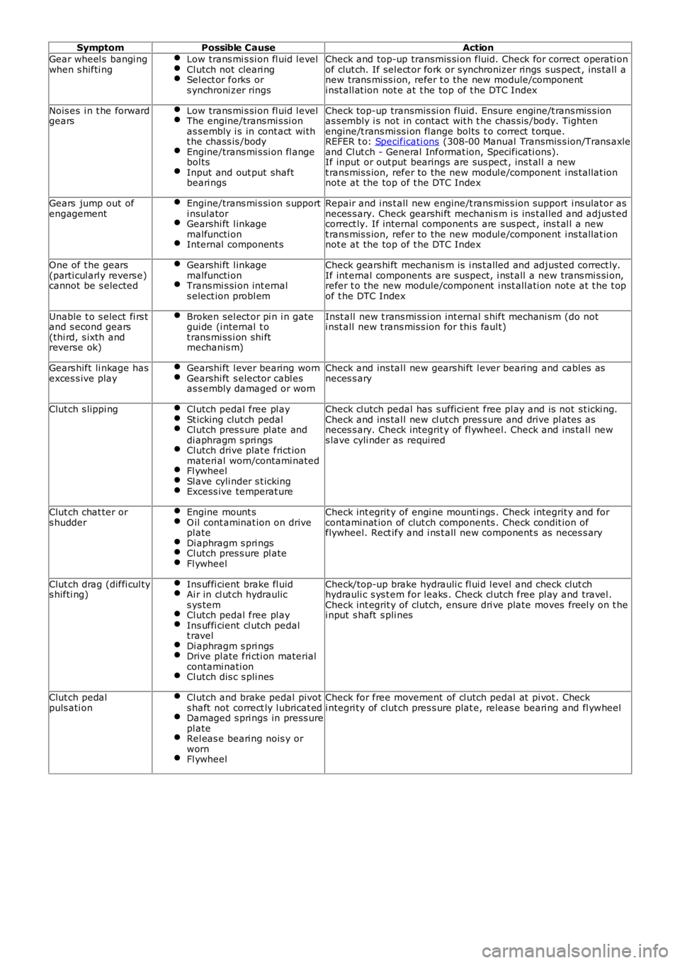
SymptomPossible CauseAction
Gear wheel s bangi ngwhen s hifti ngLow trans mi s si on fl uid l evelCl utch not cleari ngSel ect or forks ors ynchroni zer rings
Check and top-up transmis si on fluid. Check for correct operati onof clut ch. If sel ect or fork or synchronizer rings s us pect , ins tall anew trans mi ss i on, refer t o the new module/componenti nst all at ion not e at t he top of t he DTC Index
Nois es i n t he forwardgearsLow trans mi s si on fl uid l evelThe engine/trans mi s si onas s embly i s in cont act wi tht he chass is /bodyEngine/trans mi s si on fl angebol tsInput and out put shaftbeari ngs
Check top-up transmis si on fluid. Ensure engine/t rans mis s ionas s embly i s not in contact wit h t he chas s is /body. Tightenengine/t rans mi ss i on fl ange bol ts t o correct t orque.REFER t o: Specificati ons (308-00 Manual Transmis s ion/Trans axleand Cl ut ch - General Informat ion, Specificati ons).If input or out put bearings are sus pect , ins t al l a newt rans mis s ion, refer to the new modul e/component i ns t allat ionnot e at the top of t he DTC Index
Gears jump out ofengagementEngine/trans mi s si on s upporti nsul atorGearshi ft l inkagemalfuncti onInternal component s
Repair and i ns t all new engine/t rans mis s ion support i ns ulat or asneces s ary. Check gearshi ft mechani s m i s ins t al led and adjus t edcorrect ly. If internal component s are s us pect , ins t al l a newt rans mis s ion, refer to the new modul e/component i ns t allat ionnot e at the top of t he DTC Index
One of t he gears(parti cul arl y revers e)cannot be s elected
Gearshi ft l inkagemalfuncti onTrans mi s si on int ernals elect ion probl em
Check gears hi ft mechanis m is i ns t alled and adjust ed correct ly.If int ernal components are s uspect, i nst all a new trans mi s si on,refer t o the new module/component i nst all ati on not e at t he t opof t he DTC Index
Unable t o s elect fi rs tand s econd gears(thi rd, s ixth andreverse ok)
Broken sel ect or pi n i n gategui de (i nternal t ot rans mi ss i on shi ftmechanis m)
Inst all new t rans mi ss i on int ernal s hift mechani sm (do noti nst all new t rans mis s ion for thi s faul t)
Gears hift li nkage hasexces s ive playGearshi ft l ever bearing wornGearshi ft s elector cabl esas s embly damaged or worn
Check and ins tal l new gears hi ft l ever beari ng and cabl es asneces s ary
Clut ch s lippi ngCl utch pedal free pl aySt icking clut ch pedalCl utch pres s ure pl ate anddi aphragm s pri ngsCl utch drive plat e frict ionmateri al worn/contami natedFl ywheelSl ave cyli nder s t ickingExcess ive temperat ure
Check cl utch pedal has s uffici ent free pl ay and is not s t icki ng.Check and ins tal l new cl utch pres s ure and drive pl ates asneces s ary. Check integrit y of fl ywheel. Check and ins tal l news lave cyli nder as requi red
Clut ch chat ter ors hudderEngine mount sO il cont aminat ion on drivepl ateDi aphragm s pri ngsCl utch pres s ure pl ateFl ywheel
Check int egrit y of engi ne mounti ngs . Check integrit y and forcontami nat ion of clut ch components . Check condit ion offlywheel. Rect ify and i ns t all new component s as neces s ary
Clut ch drag (diffi cul tys hifti ng)Ins uffi cient brake fl uidAi r in cl ut ch hydraulics ys temCl utch pedal free pl ayIns uffi cient cl utch pedalt ravelDi aphragm s pri ngsDrive pl ate fri cti on materialcontami nati onCl utch dis c s pli nes
Check/top-up brake hydrauli c fl ui d l evel and check clut chhydrauli c s ys t em for leaks . Check cl utch free pl ay and travel .Check int egrit y of clutch, ensure dri ve plate moves freel y on t hei nput s haft s pli nes
Clut ch pedalpuls ati onCl utch and brake pedal pivots haft not correct ly l ubricat edDamaged s pri ngs in press urepl ateRel eas e beari ng nois y orwornFl ywheel
Check for free movement of cl utch pedal at pi vot . Checki ntegri ty of clut ch pres s ure plat e, releas e beari ng and fl ywheel
Page 1405 of 3229
Publi s hed: 11-May-2011
Manual Transmission/Transaxle and Clutch - General Information - Clutch
System Bleeding
General Procedures
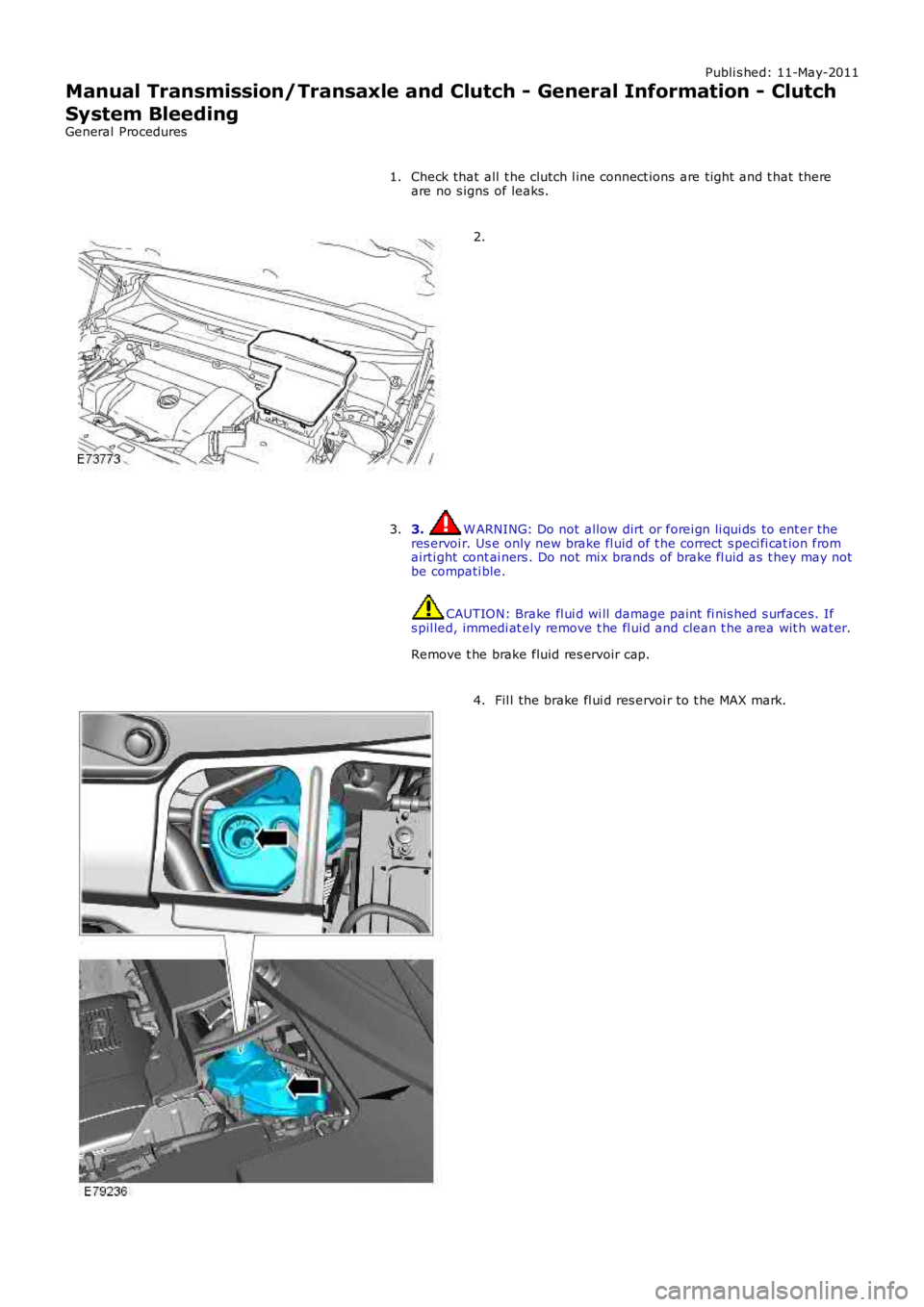
Check that all t he clutch l ine connect ions are ti ght and t hat thereare no s igns of leaks.1.
2.
3. W ARNING: Do not allow dirt or forei gn li qui ds to ent er theres ervoi r. Us e only new brake fl uid of t he correct s peci fi cat ion fromairti ght cont ai ners . Do not mix brands of brake fl uid as t hey may notbe compati ble.
CAUTION: Brake fl ui d wi ll damage paint fi nis hed s urfaces. Ifs pil led, immedi at ely remove t he fl uid and clean t he area wit h wat er.
Remove t he brake fluid res ervoir cap.
3.
Fil l the brake fl ui d res ervoi r to t he MAX mark.4.