2006 LAND ROVER FRELANDER 2 brake
[x] Cancel search: brakePage 1245 of 3229
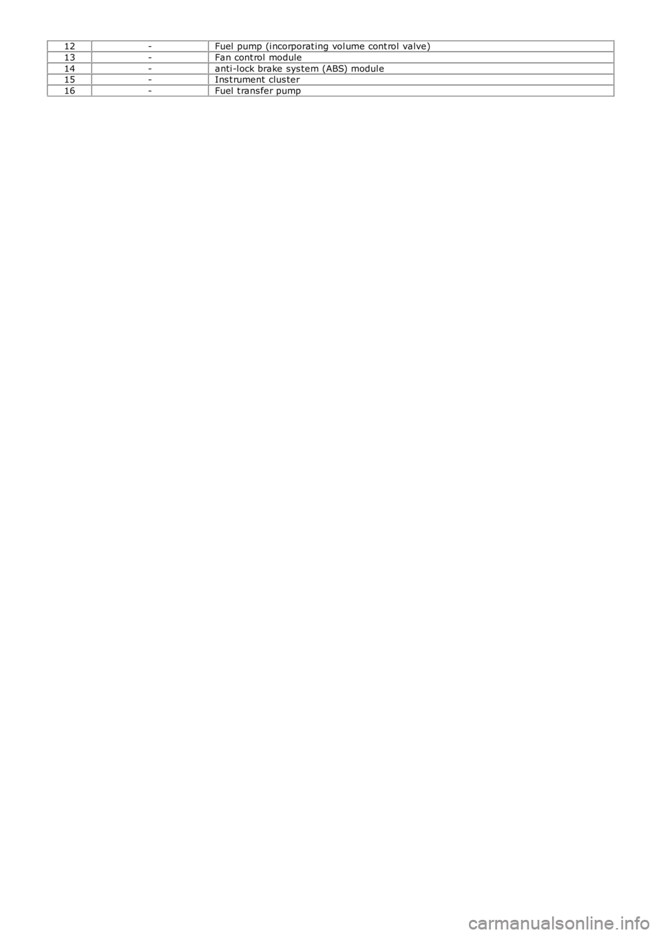
12-Fuel pump (i ncorporat ing vol ume cont rol valve)
13-Fan cont rol module
14-anti -l ock brake sys tem (ABS) modul e15-Ins t rument clus ter
16-Fuel t rans fer pump
Page 1246 of 3229
Publi shed: 12-Jul-2011
Electronic Engine Controls - TD4 2.2L Diesel - Electronic Engine Controls
Diagnosi s and Tes ti ng
Principles of Operation
For a detail ed descripti on of the el ect ronic engi ne cont rols , refer to the relevant Des cri pti on and Operati on s ect ion i n t heworks hop manual .REFER to: Elect ronic Engine Cont rols (303-14 El ect ronic Engine Cont rols - TD4 2.2L Di esel , Des cri pti on and Operati on).
Inspection and Verification
CAUTION: Di agnos is by s ubs ti tut ion from a donor vehicle is NO T acceptabl e. Subs ti tut ion of cont rol modules doesnot guarant ee confirmat ion of a faul t, and may als o caus e addit ional fault s i n t he vehi cl e being t est ed and/or t he donorvehi cl e.
1. Verify t he cus t omer concern.1.
2. Vis ually ins pect for obvious s igns of mechani cal or electrical damage and sys tem integrit y.2.
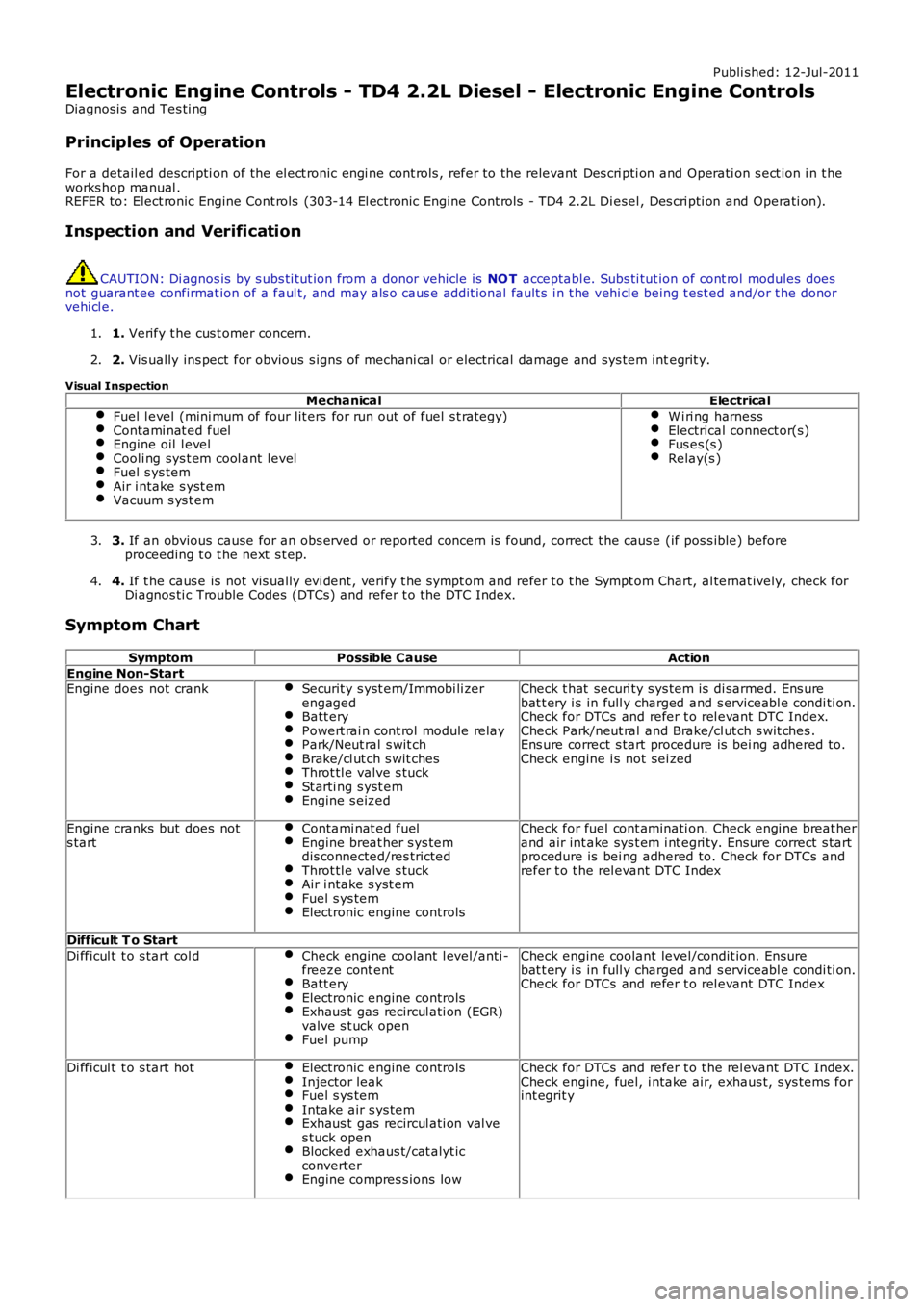
Visual InspectionMechanicalElectrical
Fuel l evel (mini mum of four lit ers for run out of fuel s t rategy)Contami nat ed fuelEngine oil l evelCooli ng sys t em cool ant levelFuel s ys temAir i ntake s yst emVacuum s ys t em
W i ri ng harnessElectrical connect or(s)Fus es (s )Relay(s )
3. If an obvious cause for an obs erved or report ed concern is found, correct t he caus e (if pos s ible) beforeproceeding t o t he next s t ep.3.
4. If t he caus e is not vis ually evi dent , verify t he sympt om and refer t o t he Sympt om Chart, al ternat ively, check forDi agnos ti c Trouble Codes (DTCs) and refer t o t he DTC Index.4.
Symptom Chart
SymptomPossible CauseAction
Engine Non-StartEngine does not crankSecurit y s yst em/Immobi li zerengagedBatt eryPowert rai n cont rol module relayPark/Neut ral s wit chBrake/cl ut ch s wit chesThrot tl e valve s tuckSt arti ng s yst emEngine s eized
Check t hat securi ty s ys tem is di sarmed. Ens urebat t ery i s in full y charged and s erviceabl e condi ti on.Check for DTCs and refer t o rel evant DTC Index.Check Park/neut ral and Brake/cl ut ch s wit ches .Ens ure correct s tart procedure is bei ng adhered to.Check engine i s not sei zed
Engine cranks but does nots tartContami nat ed fuelEngine breat her s ys temdis connected/res trictedThrot tl e valve s tuckAir i ntake s yst emFuel s ys temElectronic engine controls
Check for fuel cont aminati on. Check engi ne breat herand air int ake sys t em i nt egri ty. Ensure correct s tartprocedure is bei ng adhered to. Check for DTCs andrefer t o t he rel evant DTC Index
Difficult T o Start
Di fficul t t o s tart col dCheck engi ne coolant l evel/anti -freeze cont entBatt eryElectronic engine controlsExhaus t gas recircul ati on (EGR)valve s t uck openFuel pump
Check engine coolant level/condit ion. Ensurebat t ery i s in full y charged and s erviceabl e condi ti on.Check for DTCs and refer t o rel evant DTC Index
Di fficul t t o s tart hotElectronic engine controlsInjector leakFuel s ys temIntake air s ys temExhaus t gas recircul ati on val ves tuck openBlocked exhaus t/cat alyt icconverterEngine compres s ions low
Check for DTCs and refer t o t he rel evant DTC Index.Check engine, fuel, i ntake air, exhaus t, s ys tems forint egrit y
Page 1279 of 3229
puts t he t rans mis s ion i nto el ect roni c manual 'CommandShift™ ' mode.For addit ional informat ion, refer t o: Ext ernal Control s (307-05 Automat ic Trans mi s si on/Trans axl e External Controls ,Des cript ion and Operat ion).
The AW F21 trans mi s si on has the foll owing feat ures :
Des igned to be maint enance freeTorque capacit y of 450 NmTrans mis s ion flui d is fi ll for l ifeThe t orque convert er features a control led s l ip feature wit h elect ronically regulat ed lock-up cont rol on gears 2 t o 6Shift programs controll ed by the TCMTCM has an adapti ve capabil it y to ens ure efficient gear s hift qualit y t hroughout t he s ervice l ife of the t rans mi ss i onDiagnost ics avail abl e from the TCM vi a t he high s peed Control ler Area Network (CAN) bus .
TRANSMISSION
The t ransmis s ion compri ses the mai n casi ng which hous es al l of the t rans mi ss ion components . The torque convert er islocated i n a separat e convert er hous i ng.
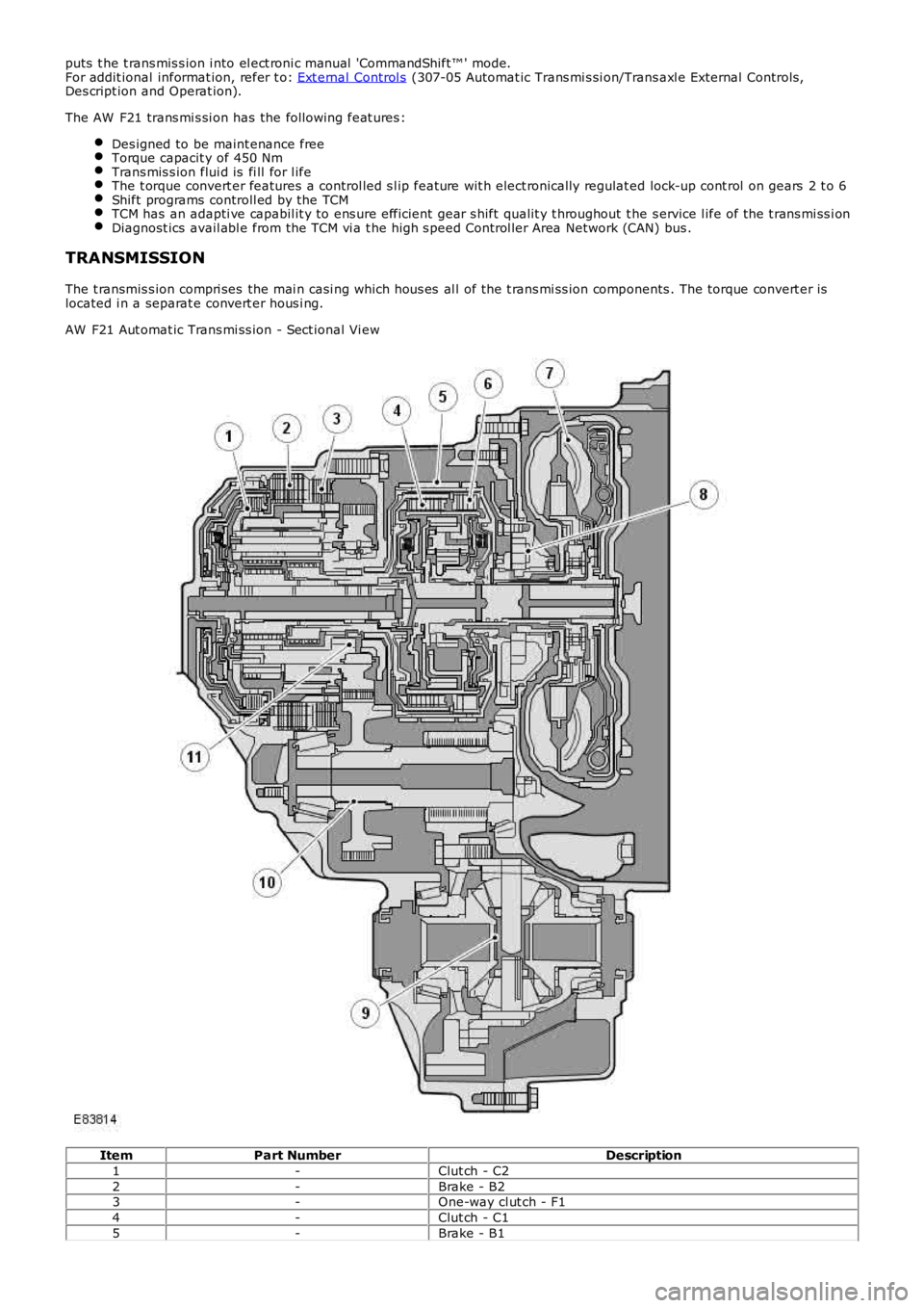
AW F21 Aut omat ic Trans mi ss ion - Sect ional Vi ew
ItemPart NumberDescription
1-Clut ch - C2
2-Brake - B23-One-way cl ut ch - F1
4-Clut ch - C1
5-Brake - B1
Page 1281 of 3229
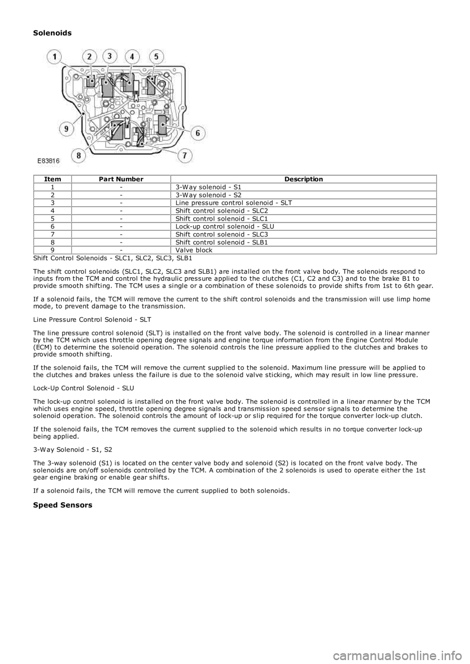
Solenoids
ItemPart NumberDescription
1-3-W ay s olenoi d - S1
2-3-W ay s olenoi d - S23-Line press ure cont rol s ol enoi d - SLT
4-Shift cont rol s ol enoi d - SLC2
5-Shift cont rol s ol enoi d - SLC16-Lock-up cont rol s olenoi d - SLU
7-Shift cont rol s ol enoi d - SLC3
8-Shift cont rol s ol enoi d - SLB19-Valve bl ock
Shift Cont rol Solenoids - SLC1, SLC2, SLC3, SLB1
The s hift control sol enoi ds (SLC1, SLC2, SLC3 and SLB1) are ins tal led on t he front valve body. The s olenoids respond t oinputs from t he TCM and control the hydrauli c pres s ure appli ed to the clut ches (C1, C2 and C3) and to the brake B1 t oprovide s moot h s hifti ng. The TCM us es a si ngl e or a combinat ion of t hes e s olenoids to provi de shi ft s from 1s t t o 6t h gear.
If a s ol enoi d fai ls , t he TCM wi ll remove t he current t o t he s hift cont rol s ol enoi ds and the trans mi s si on wil l use limp homemode, to prevent damage t o t he transmis s ion.
Line Pres s ure Cont rol Solenoid - SLT
The li ne pres s ure control s olenoid (SLT) is i nst all ed on t he front val ve body. The sol enoi d i s cont roll ed in a l inear mannerby t he TCM which us es t hrott le openi ng degree s ignals and engine t orque i nformat ion from t he Engi ne Control Module(ECM) t o det ermi ne the sol enoid operati on. The s olenoid controls t he l ine pres s ure appli ed t o t he cl utches and brakes toprovide s moot h s hifti ng.
If the s olenoid fail s, t he TCM will remove the current s uppl ied t o t he s ol enoi d. Maxi mum l ine press ure wil l be appl ied t ot he cl utches and brakes unl ess the fail ure i s due t o the sol enoi d val ve s ti cki ng, whi ch may res ult i n low li ne pres s ure.
Lock-Up Cont rol Solenoid - SLU
The lock-up control sol enoid is i nst all ed on t he front val ve body. The s ol enoi d i s cont roll ed in a l inear manner by t he TCMwhich us es engi ne s peed, t hrott le openi ng degree s ignals and t rans mis s ion s peed s ensor s ignals t o det ermi ne thes olenoi d operat ion. The sol enoi d cont rol s the amount of l ock-up or s l ip requi red for the t orque converter l ock-up cl utch.
If the s olenoid fail s, t he TCM removes the current s uppli ed t o t he sol enoi d which resul ts i n no t orque converter l ock-upbeing appli ed.
3-W ay Solenoi d - S1, S2
The 3-way sol enoid (S1) i s located on t he center valve body and s ol enoi d (S2) i s located on the front valve body. Thes olenoi ds are on/off s olenoids control led by the TCM. A combi nat ion of t he 2 s olenoids i s us ed to operat e ei ther the 1s tgear engine braki ng or enabl e gear s hift s.
If a s ol enoi d fai ls , t he TCM wi ll remove t he current s uppli ed to bot h s olenoids .
Speed Sensors
Page 1282 of 3229
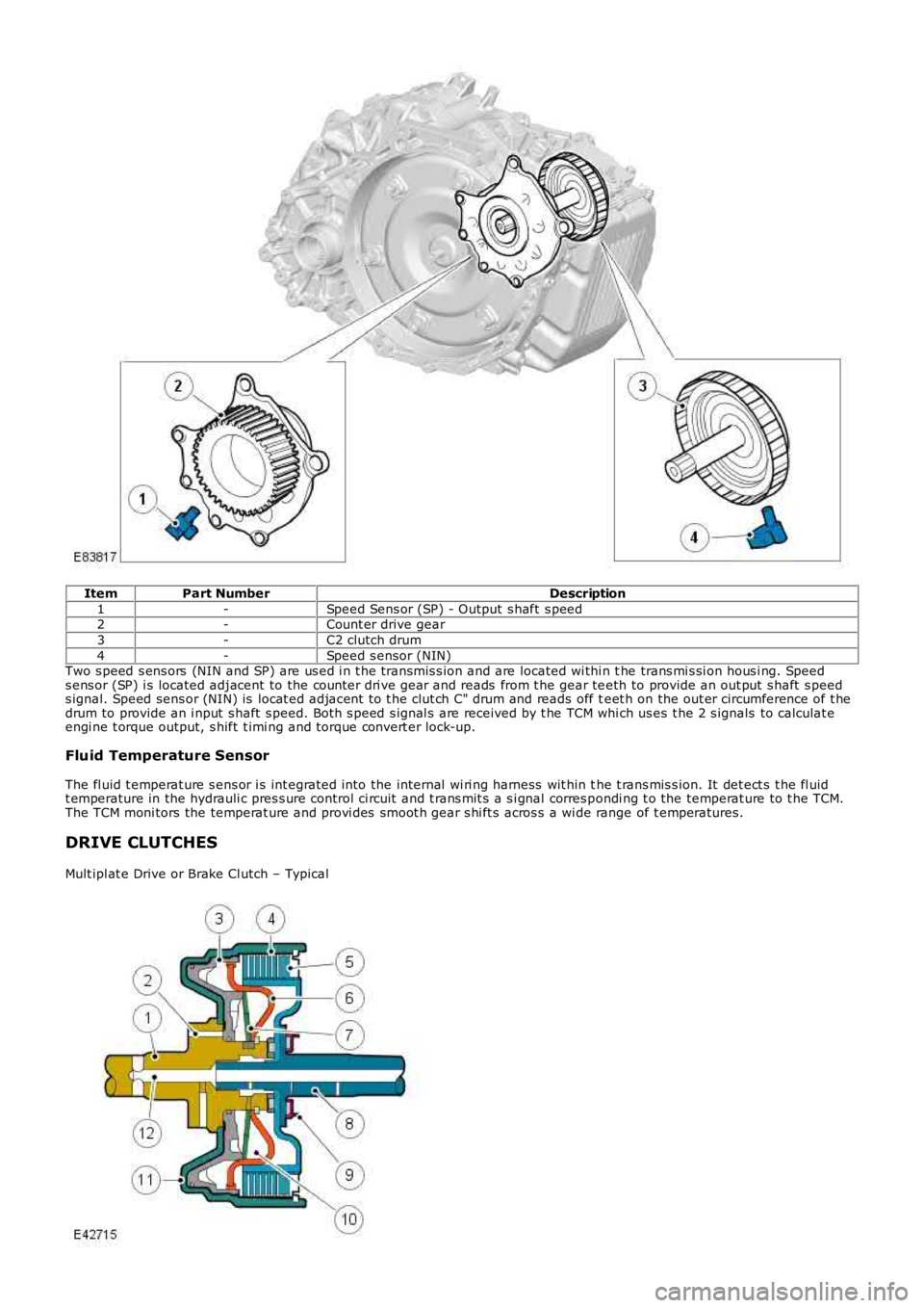
ItemPart NumberDescription
1-Speed Sens or (SP) - Output s haft s peed2-Count er drive gear
3-C2 clutch drum
4-Speed s ensor (NIN)Two s peed s ens ors (NIN and SP) are us ed i n t he transmis s ion and are located wi thi n the trans mi s si on hous i ng. Speeds ens or (SP) i s located adjacent to the counter dri ve gear and reads from t he gear teeth to provide an out put s haft s peeds ignal. Speed sens or (NIN) is locat ed adjacent to t he clut ch C" drum and reads off teet h on the out er circumference of t hedrum to provide an i nput s haft s peed. Bot h s peed s ignal s are received by t he TCM which us es t he 2 s ignals to calculat eengi ne t orque output, s hift t imi ng and torque convert er lock-up.
Fluid Temperature Sensor
The fl uid t emperat ure s ens or i s int egrated into the internal wi ri ng harness wit hin the t rans mis s ion. It det ect s t he fl uidt emperature in the hydrauli c pres s ure control ci rcuit and t rans mit s a s i gnal corres pondi ng t o the temperat ure to t he TCM.The TCM moni tors the temperat ure and provi des smoot h gear s hi ft s acros s a wi de range of t emperatures.
DRIVE CLUTCHES
Mult ipl at e Drive or Brake Cl utch – Typical
Page 1283 of 3229
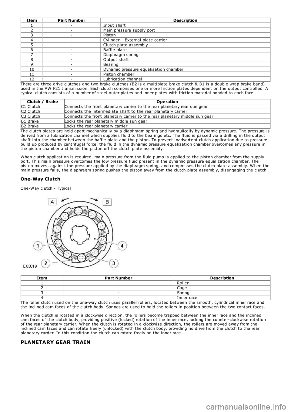
ItemPart NumberDescription
1-Input s haft
2-Main press ure supply port3-Pis ton
4-Cyl inder – External plat e carrier
5-Clutch pl ate as s embly6-Baffl e plat e
7-Diaphragm spring
8-Output s haft9-Bearing
10-Dynami c pres s ure equalis at ion chamber
11-Pis ton chamber12-Lubricati on channel
There are t hree dri ve clutches and t wo brake clut ches (B2 i s a mul ti pl ate brake clutch & B1 i s a doubl e wrap brake band)us ed in t he AW F21 t ransmis s ion. Each clut ch compris es one or more frict ion plat es dependent on the out put cont roll ed. At ypi cal clutch cons is ts of a number of s teel outer plat es and inner plates wit h frict ion mat eri al bonded to each face.
Clutch / BrakeOperation
C1 Cl utchConnect s t he front pl anet ary carrier t o t he rear planetary rear s un gearC2 Cl utchConnect s t he int ermediat e s haft t o t he rear planetary carri er
C3 Cl utchConnect s t he front pl anet ary carrier t o t he rear planetary mi ddl e s un gear
B1 BrakeLocks the rear pl anet ary middle s un gearB2 BrakeLocks the rear pl anet ary carrier
The clutch pl ates are held apart mechanically by a diaphragm spring and hydrauli cal ly by dynamic press ure. The press ure isderi ved from a l ubricati on channel which s uppl ies fluid to the beari ngs etc. The fl uid i s pass ed vi a a drill ing i n t he outputs haft int o t he chamber between t he baffle pl ate and the pi st on. To prevent i nadvert ent cl utch appli cat ion due t o pres s urebuild up produced by cent ri fugal force, the flui d in the dynamic pres sure equal ization chamber overcomes any pres sure i nt he pis ton chamber and hol ds the pi s ton off the cl ut ch plat e as sembl y.
W hen clut ch appl icati on is required, mai n pres s ure from the fl ui d pump i s applied to t he pis t on chamber from the supplyport . Thi s mai n pres s ure overcomes t he low press ure fl uid present in the dynamic pres sure equal izati on chamber. Thepis t on moves , agains t the press ure appl ied by t he diaphragm s pring, and compres ses the clut ch plate ass embly. W hen themain pres sure fal ls , t he diaphragm s pring pus hes t he pis t on away from the clut ch plate ass embly, dis engagi ng t he cl utch.
One-Way Clutch
One-W ay cl utch - Typical
ItemPart NumberDescription
1-Roller2-Cage
3-Spring
4-Inner raceThe rol ler clutch us ed on t he one-way clut ch uses parallel rol lers, l ocat ed between t he s mooth, cyl indri cal i nner race andt he inclined cam faces of the clut ch body. Spri ngs are us ed t o hold t he rol lers in pos it ion bet ween t he two cont act faces .
W hen t he clut ch is rotat ed in a clockwi se direct ion, the roll ers become t rapped bet ween t he inner race and t he incli nedcam faces of t he clutch body, providing pos it ive (locked) rotat ion of t he inner race, locki ng the counter-clockwis e rot ati onof the rear planet ary carri er. W hen t he clut ch is rotat ed in a cl ockwi se direct ion, the roll ers are moved away from t heincli ned cam faces and can rot ate freel y (unl ocked) wit h t he cl utch body, provi ding no drive from the cl ut ch t o t he rearplanetary carri er. In t hi s condi ti on the cl utch can rot ate freel y on t he inner race.
PLANETARY GEAR TRAIN
Page 1284 of 3229
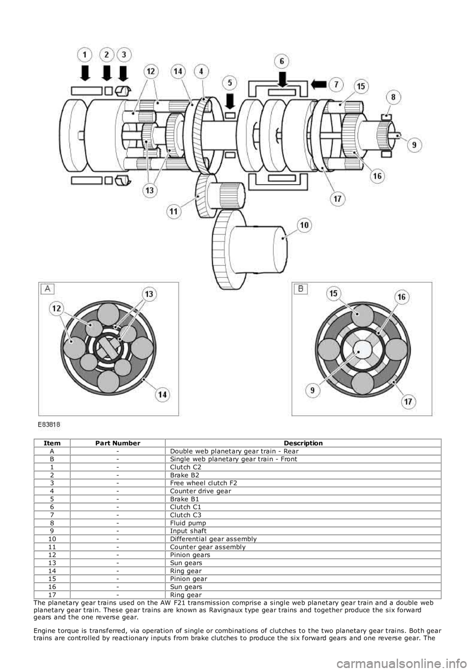
ItemPart NumberDescription
A-Doubl e web pl anet ary gear train - RearB-Single web planetary gear t rai n - Front
1-Clut ch C2
2-Brake B23-Free wheel cl utch F2
4-Count er drive gear
5-Brake B16-Clut ch C1
7-Clut ch C3
8-Fluid pump9-Input s haft
10-Different ial gear as s embly
11-Count er gear as s embl y12-Pinion gears
13-Sun gears
14-Ring gear15-Pinion gear
16-Sun gears
17-Ring gearThe planetary gear t rai ns used on the AW F21 t rans mis s ion compris e a s i ngl e web planet ary gear train and a double webplanetary gear t rai n. Thes e gear trains are known as Ravi gnaux t ype gear t rains and together produce the s i x forwardgears and t he one revers e gear.
Engi ne t orque is trans ferred, via operat ion of s i ngl e or combi nati ons of clut ches t o t he t wo planetary gear t rai ns. Bot h geart rains are cont rol led by react ionary i nput s from brake clut ches t o produce the si x forward gears and one revers e gear. The
Page 1285 of 3229
rat ios are as fol lows :
Gear1st2nd3rd4th5th6thReverse
Ratio4.1482.3701.5561.1550.8590.6863.394
POWER FLOWS
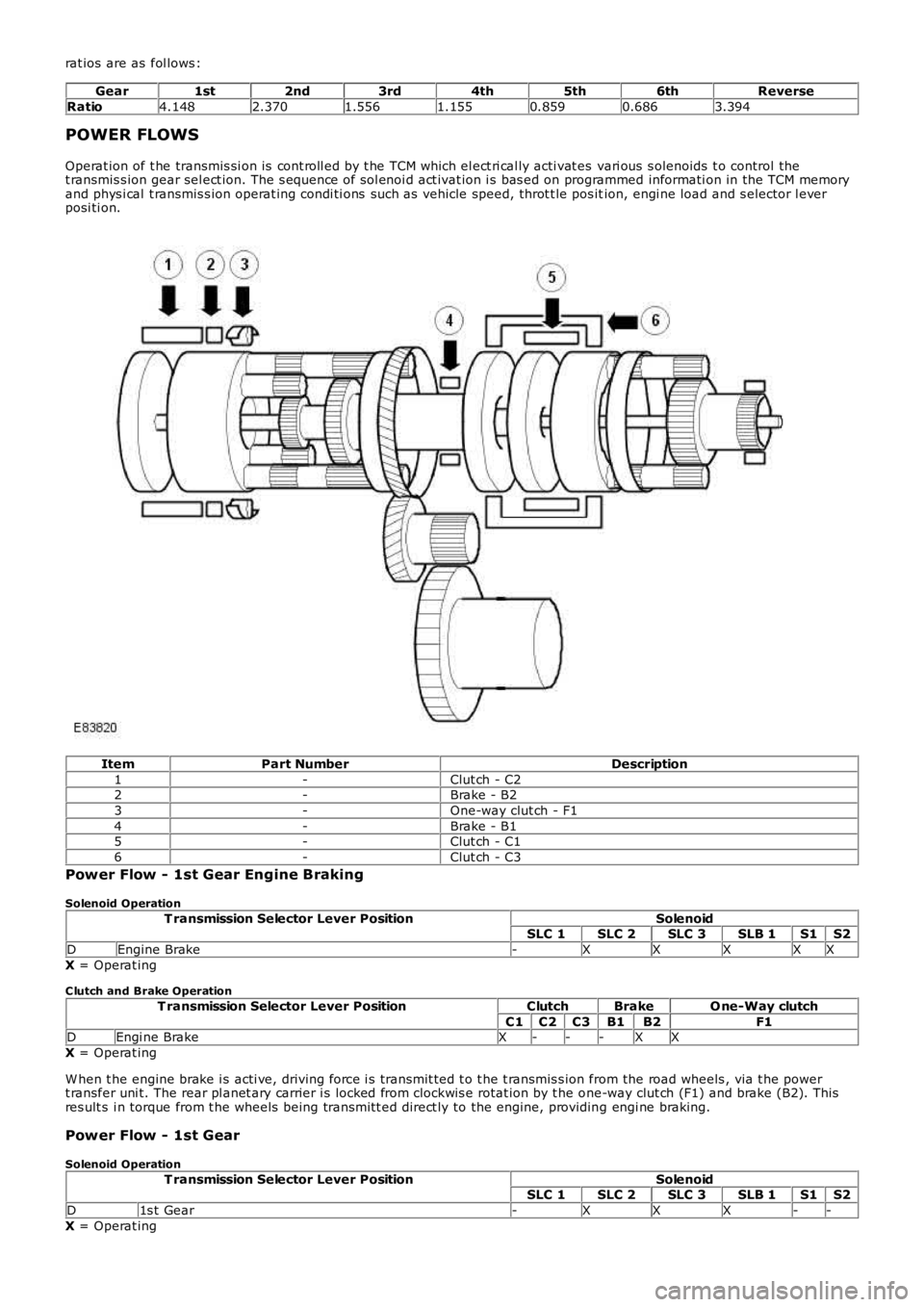
Operat ion of t he transmis si on is cont roll ed by t he TCM which el ect ri cal ly acti vat es vari ous s olenoids t o control thet ransmis s ion gear sel ect ion. The s equence of sol enoi d act ivat ion i s bas ed on programmed informati on in the TCM memoryand phys i cal t ransmis s ion operat ing condi ti ons such as vehicle speed, throt t le pos ition, engi ne load and s elector l everposi ti on.
ItemPart NumberDescription
1-Clut ch - C22-Brake - B2
3-One-way clut ch - F1
4-Brake - B15-Clut ch - C1
6-Clut ch - C3
Power Flow - 1st Gear Engine Braking
Solenoid Operation
T ransmission Selector Lever PositionSolenoidSLC 1SLC 2SLC 3SLB 1S1S2
DEngine Brake-XXXXX
X = Operat ing
C lutch and Brake Operation
T ransmission Selector Lever PositionClutchBrakeO ne-Way clutch
C1C2C3B1B2F1DEngi ne BrakeX---XX
X = Operat ing
W hen t he engine brake i s acti ve, driving force i s transmit ted t o t he t ransmis s ion from the road wheels , via t he powert ransfer uni t. The rear pl anet ary carrier i s locked from clockwis e rotat ion by t he one-way clut ch (F1) and brake (B2). Thisres ult s i n torque from t he wheels being trans mi tt ed direct ly to the engine, providing engi ne braking.
Power Flow - 1st Gear
Solenoid Operation
T ransmission Selector Lever PositionSolenoidSLC 1SLC 2SLC 3SLB 1S1S2
D1s t Gear-XXX--
X = Operat ing