2006 LAND ROVER FRELANDER 2 brake
[x] Cancel search: brakePage 791 of 3229
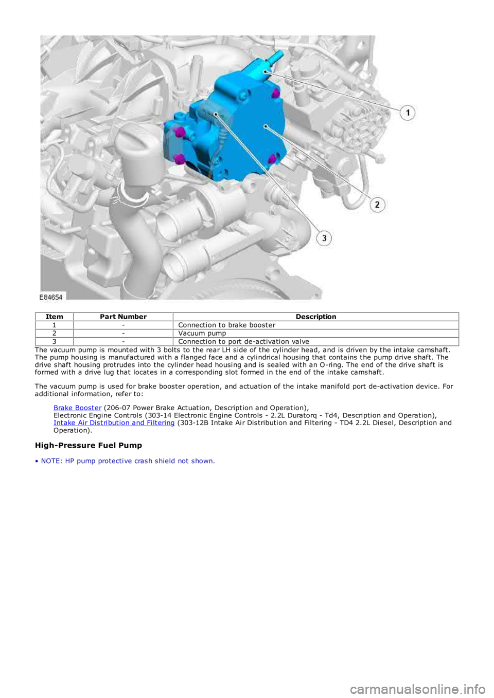
ItemPart NumberDescription
1-Connecti on t o brake boost er2-Vacuum pump
3-Connecti on t o port de-act ivati on val ve
The vacuum pump is mount ed wi th 3 bol ts to the rear LH s ide of t he cyl inder head, and is driven by t he int ake cams haft .The pump housi ng is manufact ured wit h a flanged face and a cyli ndrical hous ing that cont ains t he pump drive s haft . Thedri ve s haft hous ing protrudes into the cyli nder head housi ng and is sealed wit h an O-ri ng. The end of t he dri ve s haft isformed wi th a dri ve lug t hat locat es i n a corresponding s lot formed in t he end of the intake cams haft .
The vacuum pump is us ed for brake boos t er operat ion, and actuati on of the intake mani fold port de-acti vat ion device. Foraddi ti onal i nformat ion, refer to:
Brake Boost er (206-07 Power Brake Act uat ion, Des cript ion and Operat ion),Elect roni c Engi ne Cont rol s (303-14 Electroni c Engi ne Controls - 2.2L Duratorq - Td4, Descri pti on and Operat ion),Int ake Air Dis t ri but ion and Fi lt ering (303-12B Intake Ai r Dis tributi on and Fil tering - TD4 2.2L Dies el, Des cript ion andOperati on).
High-Pressure Fuel Pump
• NOTE: HP pump protecti ve cras h s hield not s hown.
Page 804 of 3229
1
2
3
4
5
6
7
8
9
10
11
12
1
2
3
1
2
3
4
5
6
7
8
9
• NOTE: W here pos si ble, compress i on tes t ing s houl d be carried out on an engine at normal operat ing temperat ure.
T ESTCONDIT IONSDET AILS/RESULT S/ACT IONS
A1: CARRY OUT A DRY CYLINDER COMPRESSION T EST
Make s ure t he parki ng brake is appl ied and t hat t he s elector l ever is in neutral (or park for vehi cl eswi th aut omati c transmis si on).
Set the ignit ion s t at us t o OFF.
Remove t he st art er rel ay.
Dis connect t he st art er motor s olenoid connect or.
Connect a s uit able remote st art er devi ce to the s t art er mot or s ol enoi d.
Remove t he glow pl ugs .REFER to: Gl ow Plugs (303-07B Glow Plug Sys tem, Removal and Ins tal lati on).
Ins t all s uit abl e adapt or in pl ace of t he glow plug i n t he fi rs t cyl inder to be tes t ed.
Connect a s uit able compres s ion t es ter t o the adapt or. See warni ng above.
Us ing t he remote s t art er device, crank t he engi ne a mi nimum of fi ve revoluti ons.
Record t he compres si on fi gure and t he number of revol uti ons taken to reach it .
Repeat s t eps 7 - 10 above for t he remai ning cylinders , cranking t he engine for a s imi lar number ofrevolut ions each ti me.
Compare the compres s ion figures acros s al l t he cylinders .
Are the compres s ion figures wit hi n 10% of each ot her?YesUnles s t he compres si on fi gures are uni vers al ly very low (experience wi ll indicat e thi s), check forother caus es for the cus tomer complaint .NoGO to A2.
A2: CARRY OUT A WET CYLINDER COMPRESSIO N T EST
CAUTION: If engi ne oil i s int roduced i nto the cyli nders, run t he engi ne at 2,000 rpm for a mi ni mum of t en mi nutesaft er compl eti ng tes t ing t o prevent damage to the catal yt ic convert ers . Fai lure to foll ow t his i nst ruct ion may res ul t indamage t o t he vehi cl e.
• NOTE: There is a combus ti on chamber i n the top of each pis ton. Make s ure that the oi l is not all owed t o run into thi schamber.Us ing a sui table oil can wit h a flexibl e s pout , int roduce a s mall amount of cl ean engi ne oil int o t hecyl inder jus t before tes t ing, such t hat the oi l i s able to run between t he pis t on and t he cyl inder bore.Repeat s t eps 7 - 10 from the tes t above, int roduci ng oil i nt o each cyl inder jus t before tes ti ng.
Compare the compres s ion figures acros s al l t he cylinders .
Is the compres s ion figure higher than t he dry tes t?YesA hi gher figure foll owing t he int roducti on of oi l may indi cat e a worn or damaged cyli nder bore, pi st onand/or pis t on ri ngs . Dis as s embl y would be required to confirm t his .NoIf the compres s ion figure is unaffect ed by t he int roducti on of oi l, but t he fi gure is s ti ll les s t han 90%of the ot her cyl inders , thi s may i ndi cat e a burnt and/or s t icking valve, leaking head gasket , et c.Dis as s embl y would be required to confirm t his .Clear any DTCs which may have been i nduced by t he tes t .
PINPOINT TEST B : OIL CONSUMPTION TEST
• NOTE: Oi l cons umpti on wil l vary, dependi ng on a number of fact ors . New engines will normall y us e more oil t han 'run-in'engines, once a cons umpt ion fi gure has been det ermined cont act Deal er Techni cal Support for furt her as s is t ance.T ESTCO NDIT IONSDET AILS/RESULT S/ACT IONS
B1: CHECK FOR EXCESSIVE OIL CONSUMPT IONStart the engine and al low it t o run unt il i t reaches normal operat ing temperat ure.
Make s ure t he vehi cl e i s parked on a l evel s urface and swi tch off.
All ow t o s et t le for at least five minutes .
Check t he oil l evel.
Correct t he level, i f necess ary, and record t he reading and mileage i n t he vehi cl e his t ory.
Make s ure t hat the owner/dri ver i s aware that a t est i s being carried out , and that t hey should nottop-up their oi l level for the durat ion of t he t est , but should check t he level every 160-240 Km(100-150 mil es ).
W hen t he oil l evel reaches the ADD mark, t he cust omer s houl d bri ng the vehicle in to be checked.
Top-up t he oil t o the level at t he beginning of t he tes t and record the amount of oil needed to dos o, and t he mi leage covered in the cours e of t he tes t .
From this , t he cons umpt ion can be calculated, and a decis ion made as to whet her or not t hecons umpti on is cons idered excess ive.Is the consumpt ion excess ive for the mil eage and/or us e? Contact Dealer Technical Support for furtherass is t ance.YesDis as sembl y wil l be required t o check t he components indicated i n t he s ympt om chart .NoNo furt her acti on is necess ary.
PINPOINT TEST C : CHECK THE ENGINE OIL PRESSU RE
• NOTE: The vehicle must be driven a minimum of 6 mil es (10 ki lometers ) prior t o t est ing t he oil press ure. Do not at temptt o att ain normal engi ne operati ng temperature by all owi ng t he engi ne to idle.
• NOTE: Check and, i f neces sary, t op-up t he engine oil l evel before begi nning t his test .
T EST CO NDIT IONSDET AILS/RESULT S/ACT IONSC1: CHECK FOR LOW ENGINE OIL PRESSURE
Page 902 of 3229
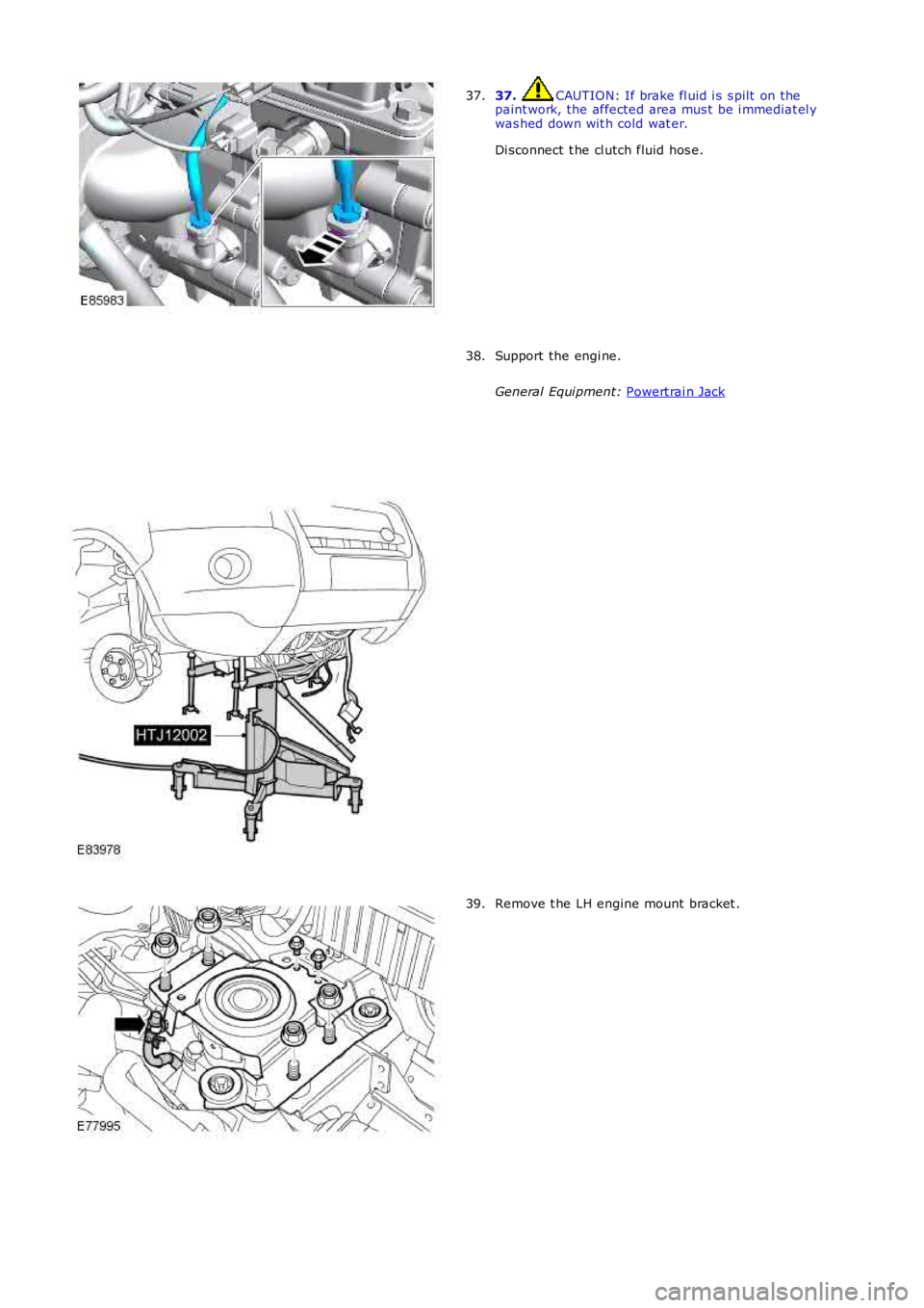
37. CAUTION: If brake fl uid i s s pilt on the
paint work, the affected area mus t be i mmediat el y
was hed down wit h cold wat er.
Di sconnect t he cl utch fluid hos e.
37. Support the engi ne.
General Equi pment: Powert rai n Jack 38.
Remove t he LH engine mount bracket .
39.
Page 906 of 3229
22. CAUTION: A new O-ring s eal is t o be ins tall ed.
Connect t he high-press ure power s t eering l ine t o t he power st eeri ng
pump.
T orque: 24 Nm 22.
Secure t he power s t eering hi gh-pres s ure l ine.
T orque: 10 Nm 23.
Inst all t he gear s elector cables .
24.
Connect t he brake boost er vacuum hos e.
25.
Connect t he ECM elect rical connectors .
26.
Inst all t he int ake ai r duct .
27.
Inst all t he charge air cool er inlet pipe.
T orque: 10 Nm 28.
Inst all t he front subframe.
Refer t o: Front Subframe (502-00 Uni -Body, Subframe and Mount ing
Syst em, Removal and Ins tall ati on).
29.
Inst all t he lower engi ne s tabil izer bar.
Refer t o: Engi ne Lower Support Ins ulat or (303-01A Engine - I6 3.2L
Petrol, Removal and Ins tall ati on).
30.
Inst all t he cat alyti c convert er.
Refer t o: Cat alyt ic Converter - Vehicles W it hout : Di es el Part iculate Fil ter (DPF) (309-00B Exhaus t Syst em - TD4 2.2L Di es el, Removal
and Inst all at ion).
31.
Refi ll and bleed t he cool ing s ys tem.
Refer t o: Cool ing Sys tem Drai ni ng, Fi lli ng and Bleeding (303-03B
Engine Cooli ng - TD4 2.2L Di esel , General Procedures ).
32.
Inst all t he air cleaner as s embly.
Refer t o: Air Cleaner (303-12A Intake Ai r Dis tribut ion and Fil tering -
I6 3.2L Pet rol, Removal and Ins t al lat ion).
33.
Inst all t he bat t ery t ray.
Refer t o: Bat t ery Tray (414-01 Bat tery, Mount ing and Cables ,
Removal and Ins tall ati on).
34.
Inst all t he plenum chamber access panel.
Refer t o: Plenum Chamber (412-01 Cl imat e Control, Removal and
Inst all at ion).
35.
Page 946 of 3229
Entrained gases i n t he cool ing s ys tem escape t hrough the t hermal control modul e degas l ine t o t he cool ant res ervoir.
The increas ing coolant temperature is felt at t he t hermos tat , and is regi s tered on the ins trument cl us t er coolantt emperature gage vi a t he ECM and ECT s ens or s i gnal.For addit ional informat ion, refer t o: Ins t rument Clus ter (413-01 Inst rument Cl us t er, Des cript ion and Operat ion).
Engine Normal Operating Temperature
W i th the coolant t emperature increas ing, at 83°C (181°F) t he t hermos tat reacts and commences openi ng. The by-pas svalve is progres s ively clos ed. Hot coolant ret urning from t he engi ne t o t he thermal control modul e i s now all owed to pas st hrough the t op hos e connecti on to the radiator. The fl ow of hot coolant t o t he radiat or now forces cold cool ant wi thi n t heradi at or and bot t om hos e t o fl ow t o t he thermal cont rol module.
Duri ng the thermos t at opening period t here i s an i nit ial temperat ure di fferenti al of t he coolant at bot h s ides of t het hermos tat . The thermos t at react s t o t he t emperature different ial and part iall y closes , whi le t he by-pas s val ve opensfurther. The thermos t at and by-pas s valve conti nue to oscil lat e whil e t he cool ant t emperat ure i ncreas es .
At a coolant temperat ure of 91°C (196°F) t he thermost at is full y opened and t he by-pas s valve i s ful ly clos ed. The returncool ant from t he engi ne is now ful ly circul ated t hrough t he radiat or and bot tom hose. Coolant flows t hrough the radiat orfrom the RH tank t o t he LH t ank, and i s cool ed by air pass i ng through the mat ri x. Ent rai ned gas es i n the radiat or es capet hrough the connect ed degas l ine t o t he cool ant res ervoir.
The increas ed cool ant volume created by heat expans ion caus es the coolant level to ri se through t he connecti ng res ervoirhose, and i nt o t he res ervoi r.
The t emperature of the cooli ng s ys t em i s cons t ant ly moni tored by t he ECM via the ECT s ens or s i gnal. The ECM uses t heECT s ignal to control operati on of the cooling fans , and to adjus t engine fueling. The ECM al so operates t he fans i nres ponse to input s from the aut omati c t ransmis s ion oil t emperat ure s ensor, Air Condit ioning (A/C) s ys tem cont rol s wit ch,and t he A/C pres sure s ens or. For addit ional i nformati on, refer to: El ect ronic Engine Cont rols - 2.2L Di es el (303-14Electroni c Engine Controls - 2.2L Dies el, Des cript ion and Operat ion).For addit ional informat ion, refer t o: Air Condit ioning (412-01 Cli mat e Cont rol , Descripti on and Operat ion).
The cool ing fan s peed is als o infl uenced by vehicle road s peed. The ECM adjus t s the speed of t he cool ing fans tocompens ate for t he ram air effect , us ing t he CAN bus road speed s ignal received from the Ant i-Lock Brake Sys tem (ABS)module.
W hen t he engine i s s hut down, t he coolant t emperature and volume decreas e. The thermos t at st art s t o clos e as t hecool ant t emperat ure decreas es to 89°C (192°F), and is fully cl osed at 81°C (178°F). The coolant level wit hin t he res ervoi rdecreas es as coolant is drawn from the res ervoi r to replenis h the s ys tem.
Followi ng engi ne s hut down when the coolant pump i s s tat ionary, the ECM may cont inue t o operat e t he cool ing fans for apre-det ermined peri od to maint ai n engine cooling.
Page 1019 of 3229
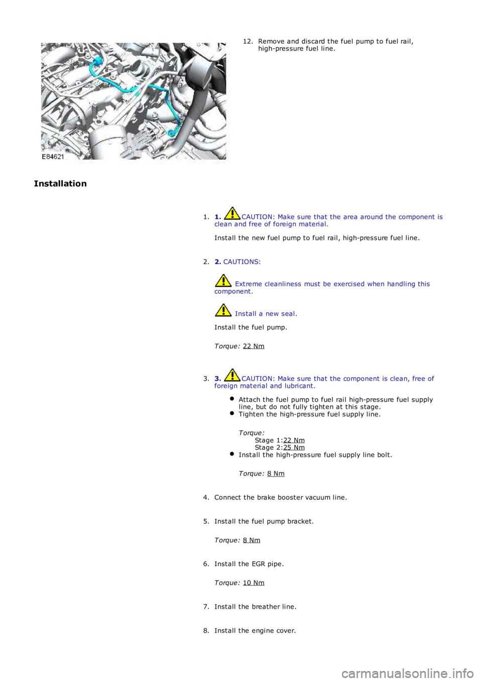
Stage 1:
Stage 2: Remove and dis card t he fuel pump t o fuel rail ,
high-pres sure fuel li ne.
12.
Installation 1. CAUTION: Make s ure that the area around t he component is
clean and free of foreign materi al.
Inst all t he new fuel pump t o fuel rail , hi gh-pres s ure fuel l ine.
1.
2. CAUTIONS: Ext reme cl eanli ness must be exerci sed when handli ng t hi s
component . Ins tall a new s eal .
Inst all t he fuel pump.
T orque: 22 Nm 2.
3. CAUTION: Make s ure that the component is clean, free of
foreign mat eri al and lubri cant.
At tach t he fuel pump t o fuel rai l high-pres s ure fuel supply
l ine, but do not fully ti ght en at t hi s s tage. Tight en the hi gh-pres s ure fuel s upply l ine.
T orque: 22 Nm 25 Nm
Inst all t he high-pres s ure fuel supply line bol t.
T orque: 8 Nm 3.
Connect t he brake boost er vacuum l ine.
4.
Inst all t he fuel pump bracket.
T orque: 8 Nm 5.
Inst all t he EGR pipe.
T orque: 10 Nm 6.
Inst all t he breather li ne.
7.
Inst all t he engi ne cover.
8.
Page 1098 of 3229
Publi s hed: 11-May-2011
Starting System - TD4 2.2L Diesel, Vehicles Built From: 01-03-2009 -
Starting System
Des cript ion and Operat ion
STOP/START SYSTEM
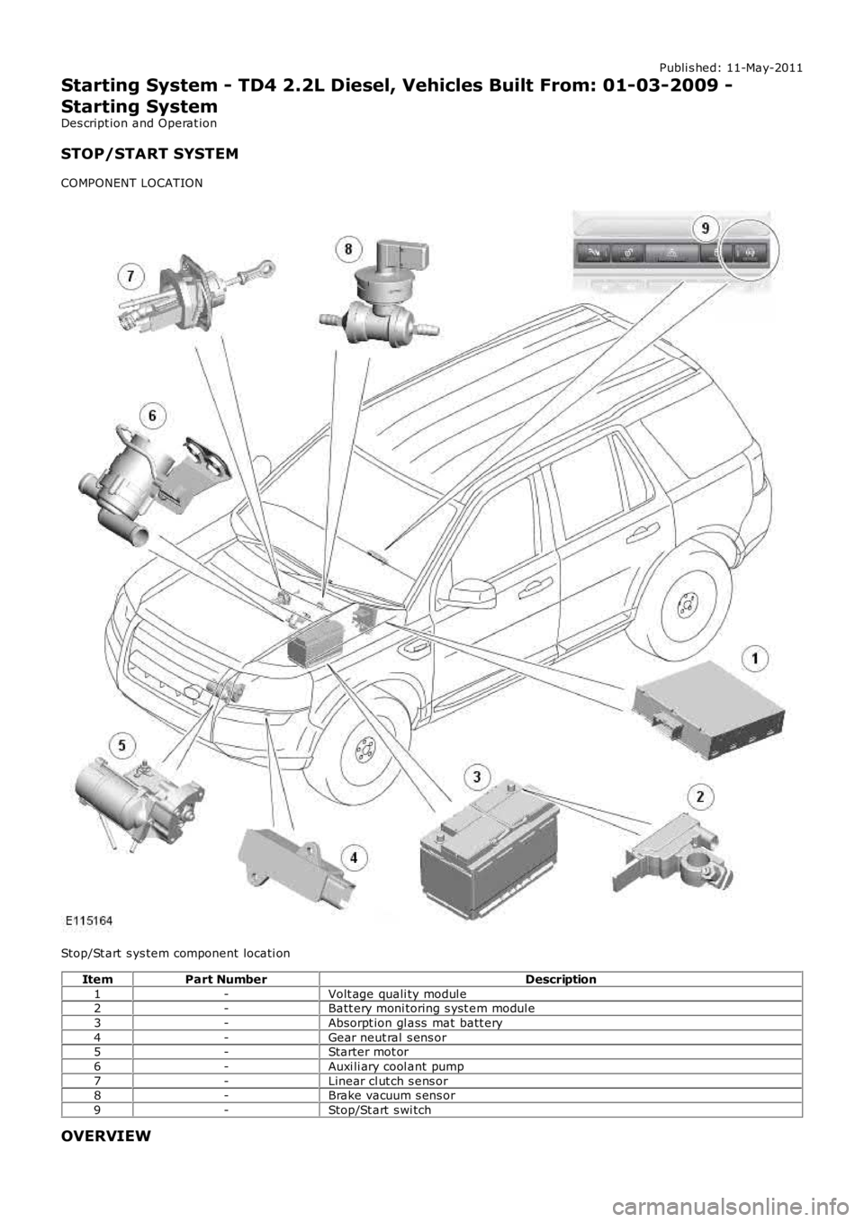
COMPONENT LOCATION
Stop/St art s ys tem component locati on
ItemPart NumberDescription
1-Volt age quali ty modul e2-Batt ery moni toring s yst em modul e
3-Absorpt ion gl ass mat batt ery
4-Gear neut ral s ens or5-Starter mot or
6-Auxi li ary cool ant pump
7-Linear cl ut ch s ens or8-Brake vacuum s ens or
9-Stop/St art s wi tch
OVERVIEW
Page 1103 of 3229
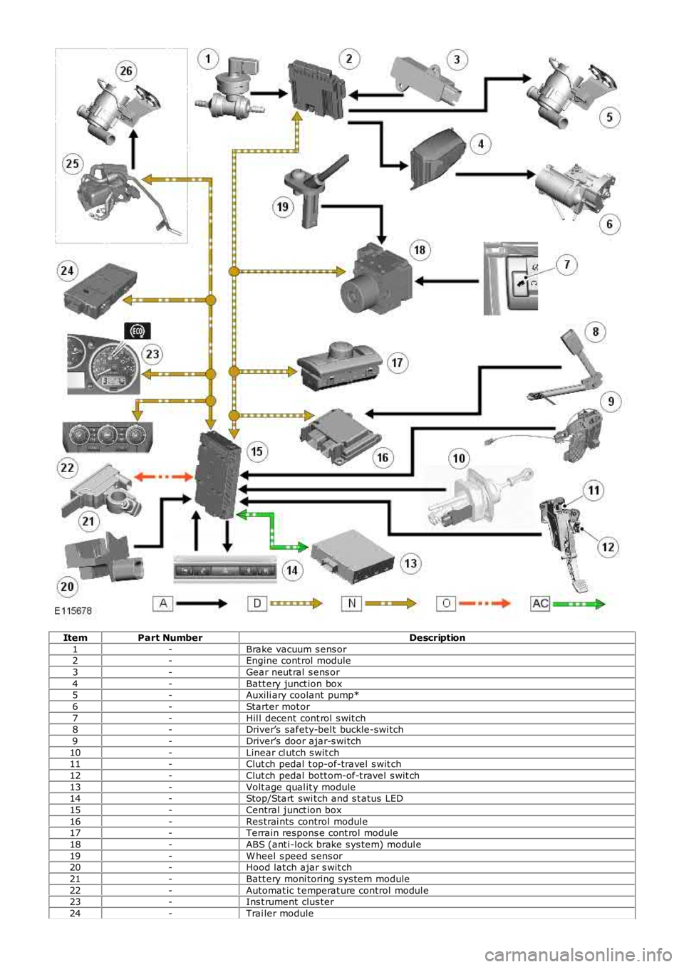
ItemPart NumberDescription
1-Brake vacuum s ens or2-Engine cont rol module
3-Gear neut ral s ens or
4-Batt ery junct ion box5-Auxili ary coolant pump*
6-Starter mot or
7-Hil l decent cont rol s wit ch8-Driver’s safety-bel t buckle-swi tch
9-Driver’s door ajar-s wi tch
10-Linear cl utch s wit ch11-Clut ch pedal t op-of-travel s wit ch
12-Clut ch pedal bott om-of-t ravel s wit ch
13-Volt age qual it y module14-Stop/Start swi tch and s t atus LED
15-Central junct ion box
16-Res trai nts control modul e17-Terrain respons e cont rol module
18-ABS (ant i-lock brake s ys tem) modul e
19-W heel s peed s ens or20-Hood lat ch ajar s wit ch
21-Batt ery moni toring s ys tem module
22-Automat ic t emperat ure control modul e23-Ins t rument clus ter
24-Trai ler module