2006 LAND ROVER FRELANDER 2 brake
[x] Cancel search: brakePage 1106 of 3229
CAUTION: To avoid damage/malfuncti oni ng of the BMS module, always us e a s uit able body ground point rather thant he bat t ery negat ive terminal when connect ing a s lave power supply.
For addit ional informat ion, refer t o: Batt ery (414-01 Bat tery, Mounti ng and Cables , Diagnos is and Tes t ing).
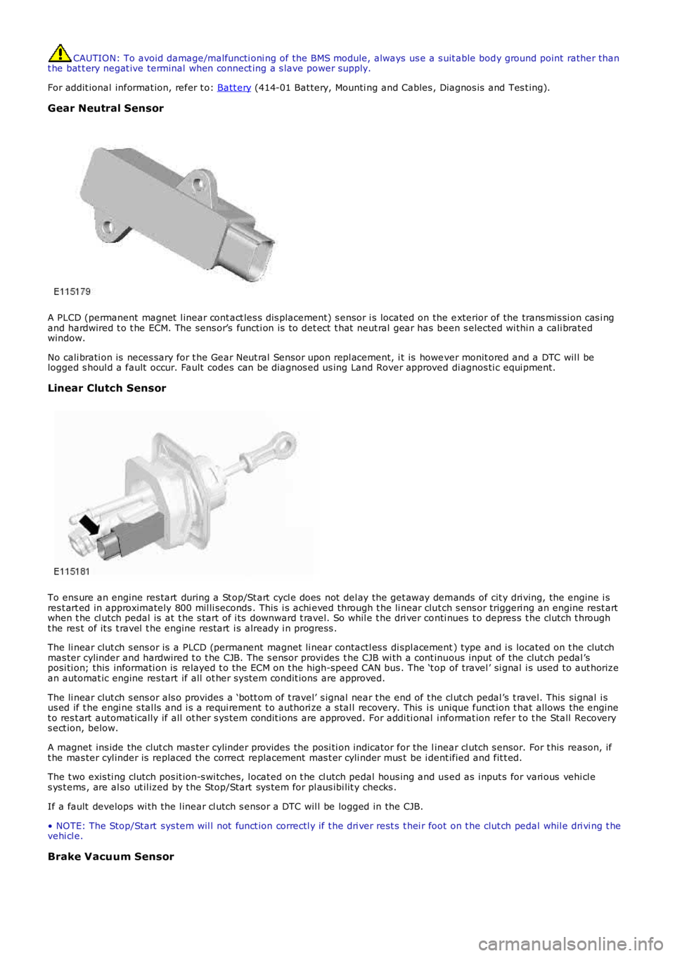
Gear Neutral Sensor
A PLCD (permanent magnet l inear cont act les s dis placement) s ensor i s located on the exterior of the trans mi s si on cas i ngand hardwired t o t he ECM. The sens or’s functi on is t o det ect t hat neut ral gear has been s elected wi thi n a cali bratedwindow.
No cali brati on is neces sary for t he Gear Neut ral Sensor upon repl acement, i t is however monit ored and a DTC wil l belogged s houl d a fault occur. Fault codes can be diagnos ed us ing Land Rover approved di agnos ti c equi pment.
Linear Clutch Sensor
To ens ure an engine res tart during a St op/St art cycl e does not del ay the get away demands of cit y dri ving, the engine i sres t art ed in approximately 800 mil li seconds . This i s achi eved through t he li near clut ch s ens or triggeri ng an engine rest artwhen t he cl utch pedal is at t he s tart of i ts downward t ravel. So whil e t he dri ver conti nues t o depres s t he clutch t hrought he res t of it s t ravel t he engine rest art i s already i n progress .
The li near clut ch s ens or is a PLCD (permanent magnet li near contactl es s di spl acement) type and i s located on t he clut chmas ter cylinder and hardwired t o t he CJB. The s ensor provi des t he CJB wi th a cont inuous input of the clut ch pedal ’sposi ti on; this informati on is relayed t o t he ECM on t he high-speed CAN bus . The ‘t op of travel ’ si gnal i s used to aut horizean automat ic engine res tart if all ot her s ys tem condit ions are approved.
The li near clut ch s ens or als o provides a ‘bott om of t ravel’ s ignal near t he end of the cl ut ch pedal ’s t ravel. This si gnal i sus ed if t he engi ne s tal ls and i s a requi rement t o authori ze a s tal l recovery. This is unique funct ion t hat allows the enginet o res t art automat ically if all ot her s ys tem condit ions are approved. For addi ti onal i nformat ion refer t o t he Stall Recoverys ect ion, below.
A magnet ins ide the clut ch mas ter cylinder provides t he posi ti on indicator for the linear cl utch s ensor. For t his reason, ift he mas ter cyl inder is replaced the correct replacement mas t er cyli nder mus t be i dent ified and fit t ed.
The t wo exis ti ng clutch pos it ion-s wi tches, l ocat ed on t he cl utch pedal hous ing and us ed as i nput s for vari ous vehi cl es ys t ems , are al so ut il ized by t he Stop/Start sys tem for pl aus ibi lit y checks .
If a fault develops wi th the l inear cl utch s ensor a DTC wil l be logged in the CJB.
• NOTE: The Stop/Start sys tem wil l not funct ion correctl y if t he dri ver rest s t hei r foot on t he clut ch pedal whil e dri vi ng t hevehi cl e.
Brake Vacuum Sensor
Page 1107 of 3229
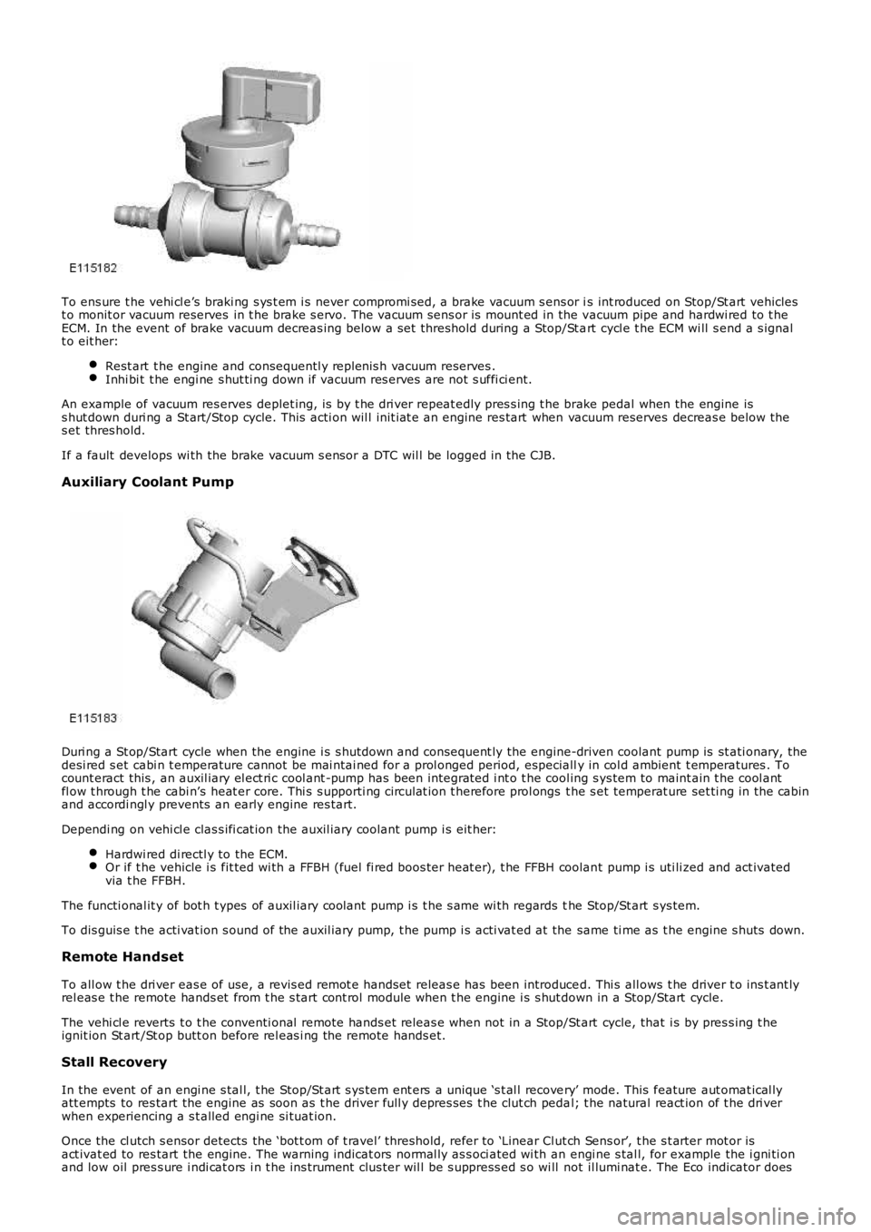
To ens ure t he vehi cl e’s braki ng s ys t em i s never compromi sed, a brake vacuum s ens or is int roduced on Stop/St art vehiclest o monit or vacuum reserves in t he brake s ervo. The vacuum sens or is mount ed in the vacuum pipe and hardwi red to t heECM. In the event of brake vacuum decreas ing below a s et threshold during a Stop/St art cycl e t he ECM wi ll s end a s ignalt o eit her:
Rest art t he engine and consequentl y replenis h vacuum reserves .Inhi bi t t he engi ne s hut ti ng down if vacuum res erves are not s uffi ci ent.
An example of vacuum res erves deplet ing, is by t he dri ver repeat edly pres s ing t he brake pedal when the engine iss hut down duri ng a St art/Stop cycle. This acti on wil l init iat e an engine res tart when vacuum reserves decreas e below thes et thres hold.
If a fault develops wi th the brake vacuum s ensor a DTC wil l be logged in the CJB.
Auxiliary Coolant Pump
Duri ng a St op/Start cycle when the engine i s s hutdown and consequent ly the engine-driven coolant pump is st ati onary, thedesi red s et cabi n t emperature cannot be mai ntai ned for a prol onged period, especially in col d ambient t emperatures . Tocount eract this , an auxil iary el ect ri c cool ant -pump has been integrat ed i nt o t he cool ing s ys tem to maint ain t he cool antfl ow t hrough t he cabi n’s heat er core. Thi s s upporti ng ci rculat ion t herefore prol ongs t he s et temperat ure set ti ng in the cabinand accordi ngl y prevents an early engine res tart.
Dependi ng on vehi cl e clas s ifi cat ion the auxil iary coolant pump i s eit her:
Hardwi red di rectl y to the ECM.Or if t he vehicle i s fit ted wi th a FFBH (fuel fi red boos ter heat er), t he FFBH coolant pump i s uti li zed and act ivatedvia t he FFBH.
The functi onal it y of bot h t ypes of auxil iary coolant pump i s t he s ame wi th regards the Stop/St art s ys tem.
To dis guis e t he acti vat ion s ound of the auxil iary pump, t he pump i s acti vat ed at the same ti me as t he engine s huts down.
Remote Handset
To all ow t he dri ver eas e of use, a revis ed remot e handset releas e has been introduced. Thi s all ows t he driver t o ins t ant lyrel eas e t he remote hands et from t he s tart cont rol module when t he engine i s s hut down in a Stop/Start cycle.
The vehi cl e reverts t o t he conventi onal remote hands et releas e when not in a Stop/Start cycle, that i s by pres s ing t heignit ion St art /St op butt on before rel eas i ng the remote hands et.
Stall Recovery
In the event of an engi ne s tal l, t he Stop/St art s ys tem ent ers a unique ‘s t al l recovery’ mode. This feature aut omat ical lyatt empts to res tart the engine as soon as t he driver full y depres ses t he clut ch pedal; t he natural react ion of t he dri verwhen experiencing a s t alled engi ne si tuat ion.
Once the cl utch s ensor detects the ‘bot t om of t ravel’ threshold, refer to ‘Linear Clut ch Sens or’, t he s t arter mot or isact ivat ed to res tart the engine. The warni ng indicat ors normal ly as s oci ated wi th an engi ne s tal l, for example the i gni ti onand low oil pres s ure i ndi cat ors i n t he ins t rument clus ter wil l be s uppress ed s o wi ll not il lumi nat e. The Eco indicator does
Page 1109 of 3229
Fuel fired heat er
The FFBH (fuel fired boost er heat er) and St op/Start s ys t em wi ll not operate si mult aneous ly, due to low ambientt emperatures bei ng a fact or in t he funct ion of both sys tems .
Hood Latch Ajar-Switch
W ARNING: To avoi d injury when performing repai r work on t he vehicle al ways di s abl e the Stop/St art s ys tem bypres s ing t he ‘ECO’ butt on, ens ure that ‘ECO STOP/START OFF’ is di s pl ayed in t he mes sage Cent er and the ECO tel l-taleli ght in t he s wit ch is ext inguis hed.
The hood lat ch ajar-s wit ch hardwired to the CJB, has two functi ons :
Acts as a s top i nhi bit or, all owing t he engi ne t o remai n running if t he hood latch i s rel eased.Deact ivates the St op/Start s ys t em i f an engi ne s top i s t aki ng place, t his res ul ts in an engine st all ed condit ion. Theengi ne can be res t art ed usi ng t he ignit ion but ton. Stal l recovery wil l not funct ion i n t hi s condi ti on; refer t o t he StallRecovery secti on.
Aft er the hood i s clos ed reacti vat ion of t he Stop/Start sys tem is achieved by manuall y s tarti ng the engine.
System Fault
The Stop/St art s ys tem is aut omati cal ly acti vat ed each ti me an ignit ion cycl e occurs; t he dri ver will be i nformed t he sys t emis operat ing by the t ell -t ale l ight in the Eco s wi tch i lluminati ng. If the tell -t ale light does not il luminat e t hi s wi ll indicat et hat t here i s eit her a s ys t em faul t or the sys tem is not avail abl e. Onl y when t he dri ver at tempt s t o act ivat e t he sys t em bypres s ing t he ‘Eco’ but ton will t hey be informed of a fault by ‘ECO STOP/START FAULT’ being di spl ayed i n t he mes sageCenter.
Owi ng to the St op/Start s ys t em’s complexit y due t o many ot her vehicle modul es and communicat ion net works i nvol ved i nit s funct ion. It i s recommended t hat al l ot her sys tem faul ts be init ial ly diagnos ed and eliminated when inves t igati ngStop/St art fault s as t hes e could affect the operat ion of t he St op/Start sys tem.
Syst em DTC (di agnos ti c troubl e code)can be diagnos ed us ing Land Rover approved di agnos ti c equi pment.
STOP INHIBITORS, START INITIATORS AND START INHIBITORS
A number of s el ect able feat ures or vehicle si tuat ions can infl uence t he operat ion of t he Stop/St art s yst em’s operati on.Thes e can, depending on the parti cular circumst ances :
prevent the engine s hutt ing down (s t op inhibi tor),ini ti at e an aut onomous res tart (s tart ini ti at or),prevent an engi ne res t art (st art i nhi bit or).
Stop Inhibitors
Under normal ci rcums tances the St op/St art s ys t em wi ll automat icall y s hut down t he engi ne if:
t he vehi cl e is st ati onary,t he trans mi s si on is in neutral,t he cl utch pedal i s ful ly releas ed.
The fol lowing condit ions wi ll inhibi t the engine from s hutt ing down:
Dri ver effected st op inhi bi tor
The fol lowing driver effect ed condi ti ons will i nhi bit t he engi ne from shut ti ng down:
Dri ver s wi tches off t he Stop/St art s ys temTrans mis s ion not i n neut ral((no te that the d rive r re sting their ha nd o n the g ea r le ve r ca n move the tra ns mis sion o ut o f the ne utra l w ind o w w itho ut e nga g ing a ge a r))
Clut ch pedal not full y rel easedAccelerator pedal depres s edHood is openDri ver’s door is openDri ver’s safet y belt i s dis engagedHDC (hil l decent cont rol) i s acti veTR (terrain res pons e) mode i s act iveCli mate cont rol s ys t em us ed above cal ibrat ed thresholdW i nds hiel d demis t i s operati ngTrai ler electrical connect ion det ect ed
Vehicle s ys tem effect ed s top i nhi bit or
The fol lowing vehicl e s ys t em condi ti ons wil l inhibit t he engine from s hut ti ng down:
Dri ver s wi tches off t he Stop/St art s ys temBrake s ervo vacuum below thres holdBatt ery cold cranki ng capabil it y below t hres holdBatt ery s t ate of charge i s lowCatal yt ic converter out si de eit her pre or post cali brati on rangeDPF (di esel part iculat e filt er) i s regenerat ingEngi ne cool ant temperat ure bel ow t hreshol dEngi ne oil t emperature below thres hold
Page 1110 of 3229
Envi ronmental effected s t op inhibi tor
The fol lowing environmental condit ions wi ll i nhi bit t he engi ne from s hutt ing down:
External t emperature above 35°CExternal t emperature below 4°C
Start Initiators
W hen t he engine has s hutdown wi thi n a St op/Start cycle the followi ng condi ti ons will i nit iate an early res tart wit hin t hes ame St op/Start cycle:
Dri ver effected st art i nit iator
The fol lowing driver effect ed condi ti ons will i nit iate an earl y engi ne res t art:
Dri ver s wi tches off t he Stop/St art s ys temVehicle s peed above cali brat ed threshold 3 Km/hour (2 mi le/hour)- A res tart will only occur if t he transmis s ion i s in neut ral and the driver’s pres ence is det ect ed for example, thedri ver’s s afet y belt remains s ecured and t he driver’s door remains latchedBrake s ervo vacuum below thres hold (dri ver operat ing brake pedal)HDC (hil l decent cont rol) i s acti vat edTR (terrain res pons e) mode i s act ivat edA hi gher heater fan speed i s s elect edW i nds hiel d demis t i s act ivat ed
Vehicle s ys tem effect ed s tart init iat or
The fol lowing vehicl e s ys t em condi ti ons wil l init iat e an earl y engine res t art :
Batt ery cranking capabili ty is near it s l ower t hres hol dBatt ery s t ate of charge i s near it s lower t hreshol dW i nds hiel d demis t acti vat esThe int eri or cabin t emperat ure decreas es bel ow or increas es above the occupant’s s et thres holds
Envi ronmental effected s t art ini ti ator
The fol lowing environmental condit ions wi ll i ni ti ate an early engi ne res tart:
External t emperature ri s es above 35°CExternal t emperature reduces bel ow 4°C
Start Inhibitors
W hen t he engine has s hutdown wi thi n a St op/Start cycle the followi ng condi ti ons will prevent an automat ic res tart :
Dri ver effected st art i nhi bit or
The fol lowing driver effect ed condi ti ons will i nhi bit an aut omati c engi ne res tart:
Hood has been openedThe accelerator pedal i s depress edGear sel ect or moved out of neutral; mes s age Cent er wil l di spl ay: ‘Sel ect Neut ral To Res tart ’Dri ver’s safet y belt i s dis engaged; t hi s i s an automat ic s t art inhi bi tor t herefore the engi ne can be res tarted bydepres si ng the cl utch pedalDri ver’s door is unl atched; t his is an aut omati c st art i nhibit or therefore t he engine can be rest art ed by depres si ngt he cl utch pedal
Vehicle s ys tem effect ed s tart inhibit or
The fol lowing vehicl e s ys t em condi ti ons wil l inhibit an aut omati c engi ne res t art :
Engi ne has s hut down for l onger t han 5 mi nut es : a conventi onal res t art wi ll be requi redThere i s a s ys tem fault
Page 1198 of 3229
4-Fuel Pump Dri ver Module (FPDM)
5-Ambi ent ai r temperat ure sens or
6-Bat tery Juncti on Box (BJB)7-Bat tery
OVERVIEW
The Engi ne Control Module (ECM) controls t he fol lowing:
Engi ne fuel ingIgni ti on ti mingClos ed loop fuelingKnock controlIdl e s peed cont rolEmis s ion controlOn Board Diagnost icsSpeed cont rol.
The ECM controls engine fuel ing by provi ding s equent ial fuel inject ion t o al l cyli nders . Ignit ion i s cont rol led by a directignit ion sys tem, provi ded by 6 pl ug top coil s . The ECM is abl e t o detect and correct for i gni ti on knock on each cyl inder andadjus t the ignit ion t imi ng for each cyl inder to achieve opt imum performance.
The ECM us es a t orque-bas ed s trategy t o generate the t orque requi red by t he dri ver and ot her vehicle cont rol modules .The ECM us es various s ens ors t o determine t he t orque requi red from the engine. The ECM al so int erfaces wi th ot hervehi cl e elect ronic control modul es vi a t he high s peed Control ler Area Network (CAN) bus , to obt ain addit ional informat ion(for exampl e road speed from the Ant i-lock Brake Sys tem (ABS) module). The ECM proces ses t hese si gnal s and deci deshow much t orque t o generate. Torque i s t hen generat ed by us ing vari ous act uat ors to supply ai r, fuel and s park t o t heengi ne.
The ECM al so us es an el ect ronic throt tl e s yst em which compris es t he electric t hrot tle as sembl y and an Accel erator PedalPosi ti on (APP) s ensor.
The ECM al so interfaces wit h t he immobili zat ion sys tem t o help prevent t he vehi cl e being s t art ed wit hout properauthori zat ion.For addit ional informat ion, refer t o: Anti -Theft - Act ive (419-01, Des cri pt ion and Operati on).
CONTROL DIAGRAM SHEET 1 OF 2
• NOTE: A = Hardwi red; N = Medium s peed CAN bus; O = Local Int erconnect Network (LIN) bus
Page 1210 of 3229
The ECM us es t he informati on from the downs tream HO2S t o enhance the s ignals from t he upst ream HO2S.
The downst ream HO2S are si mi lar in their const ructi on t o t he ups t ream HO2S wit h t he except ion of t he out put si gnal t ot he ECM. The out put si gnal i s a binary s ignal where t he amplit ude of the si gnal curve changes consi derably when t heoxygen content in the exhaust gas s es changes . The oxygen content of t he exhaus t gas ses leaving t he catalyt ic converterare measured by comparing i t wit h ambi ent ai r drawn i nt o t he HO2S.
Stop Lamp Switch
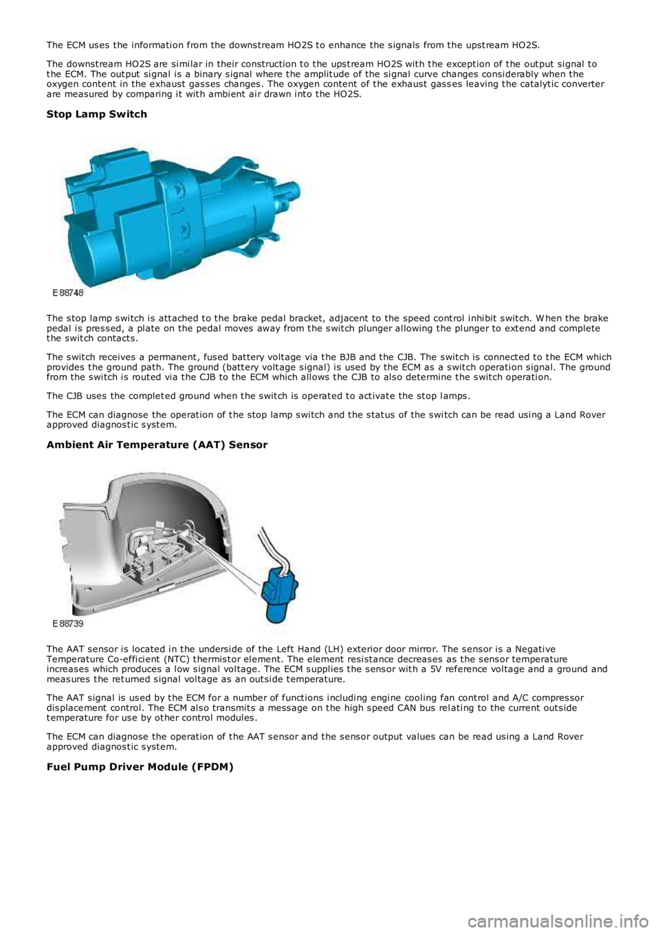
The s top l amp s wi tch i s att ached t o t he brake pedal bracket, adjacent to the speed cont rol i nhi bit s wit ch. W hen the brakepedal i s pres s ed, a pl ate on the pedal moves away from t he s wit ch plunger al lowing the pl unger to ext end and completet he swit ch contact s.
The s wit ch receives a permanent , fus ed bat t ery volt age via t he BJB and t he CJB. The s wit ch is connect ed t o t he ECM whichprovides t he ground path. The ground (batt ery volt age s ignal) i s used by the ECM as a s wit ch operati on s ignal. The groundfrom the s wi tch i s rout ed vi a t he CJB to the ECM which all ows t he CJB to al s o determine t he s wit ch operati on.
The CJB uses the complet ed ground when t he s wit ch is operat ed t o act ivat e the st op lamps .
The ECM can diagnose the operat ion of t he s top lamp s wi tch and t he s tat us of the s witch can be read usi ng a Land Roverapproved diagnos t ic s yst em.
Ambient Air Temperature (AAT) Sensor
The AAT s ensor i s located i n t he undersi de of the Left Hand (LH) exterior door mirror. The s ens or i s a Negati veTemperature Co-effi ci ent (NTC) t hermis t or el ement. The element resi st ance decreas es as t he s ens or temperatureincreas es which produces a l ow s ignal vol tage. The ECM s uppl ies t he s ens or wit h a 5V reference vol tage and a ground andmeas ures t he ret urned s ignal vol tage as an out si de t emperature.
The AAT s ignal is us ed by t he ECM for a number of funct ions i ncludi ng engi ne cool ing fan cont rol and A/C compres sordis placement control. The ECM al s o transmit s a mes s age on t he high s peed CAN bus relati ng to the current out s idet emperature for us e by ot her control modul es .
The ECM can diagnose the operat ion of t he AAT s ensor and t he s ens or output values can be read us ing a Land Roverapproved diagnos t ic s yst em.
Fuel Pump Driver Module (FPDM)
Page 1215 of 3229
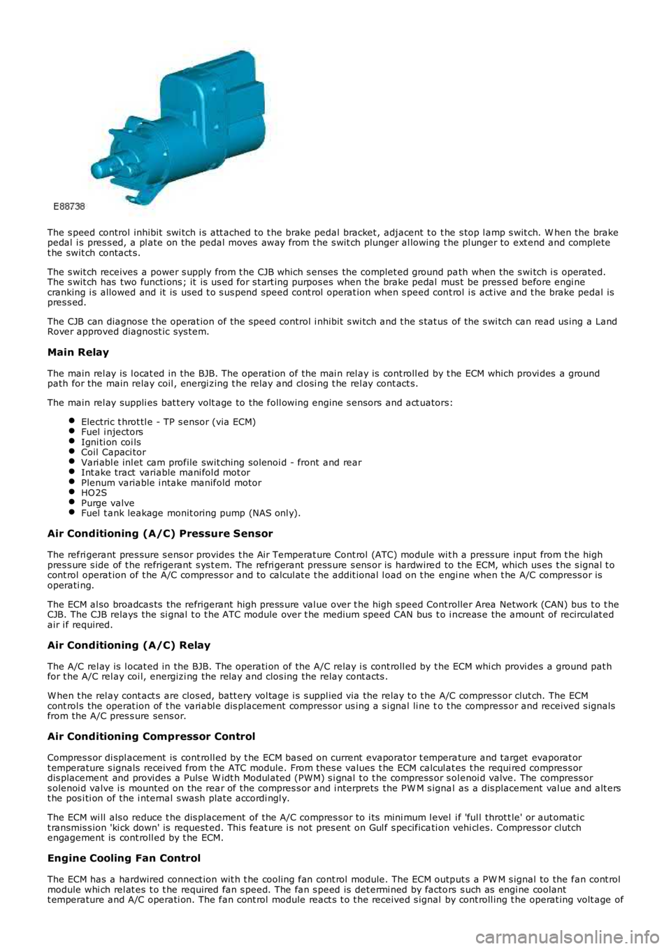
The s peed control inhibit swi tch i s att ached to t he brake pedal bracket , adjacent t o t he s top l amp s wit ch. W hen the brakepedal i s pres s ed, a pl ate on the pedal moves away from t he s wit ch plunger al lowing the pl unger to ext end and completet he swit ch contact s.
The s wit ch receives a power s upply from t he CJB which s enses the complet ed ground path when the s wi tch i s operated.The s wit ch has two functi ons ; it is us ed for s t art ing purpos es when the brake pedal mus t be pres s ed before engi necranking i s allowed and it is used t o s us pend speed cont rol operat ion when s peed cont rol i s act ive and t he brake pedal ispres s ed.
The CJB can diagnos e t he operat ion of t he speed control i nhibit s wi tch and t he s tat us of the s wi tch can read us ing a LandRover approved diagnost ic sys tem.
Main Relay
The main rel ay is l ocat ed in the BJB. The operati on of the mai n rel ay is cont roll ed by t he ECM which provi des a groundpath for the main relay coil , energi zing t he rel ay and cl osi ng t he rel ay cont act s.
The main rel ay suppli es bat t ery volt age to the foll owing engine s ensors and act uators:
Electric t hrot tl e - TP s ensor (via ECM)Fuel i njectorsIgni ti on coi lsCoil Capaci torVari abl e inl et cam profile swit ching sol enoi d - front and rearInt ake tract variable mani fol d mot orPlenum variable i ntake manifold motorHO2SPurge valveFuel t ank leakage monit oring pump (NAS onl y).
Air Conditioning (A/C) Pressure Sensor
The refri gerant pres sure s ens or provides t he Air Temperat ure Cont rol (ATC) module wit h a press ure input from t he highpres s ure s ide of t he refrigerant s ys t em. The refri gerant press ure s ens or is hardwired to the ECM, which us es t he s ignal t ocont rol operat ion of t he A/C compress or and to cal cul at e t he addit ional l oad on t he engi ne when t he A/C compress or isoperati ng.
The ECM al so broadcas ts the refrigerant high press ure val ue over t he high s peed Controller Area Network (CAN) bus t o t heCJB. The CJB relays the si gnal t o t he ATC module over t he medium speed CAN bus t o i ncreas e the amount of recircul at edair i f required.
Air Conditioning (A/C) Relay
The A/C rel ay is l ocat ed in the BJB. The operati on of the A/C relay i s cont roll ed by t he ECM whi ch provi des a ground pat hfor t he A/C rel ay coi l, energizi ng the relay and clos ing the relay cont acts .
W hen t he rel ay cont act s are clos ed, batt ery vol tage i s s uppl ied via the relay t o t he A/C compress or clut ch. The ECMcont rol s the operat ion of t he vari abl e dis placement compress or us ing a s i gnal li ne to t he compress or and received s ignalsfrom the A/C pres s ure sens or.
Air Conditioning Compressor Control
Compres s or di spl acement is cont roll ed by t he ECM bas ed on current evaporator t emperature and target evaporat ort emperature s ignals received from t he ATC module. From thes e values t he ECM calcul ates t he requi red compres s ordis placement and provi des a Puls e W idt h Modul ated (PW M) s i gnal t o t he compress or s olenoi d valve. The compress ors olenoi d valve i s mounted on the rear of t he compres s or and i nterprets the PW M s ignal as a dis placement val ue and alt erst he pos i ti on of the i nternal s wash plate accordi ngl y.
The ECM wi ll als o reduce t he dis placement of the A/C compres s or to i ts mini mum l evel i f 'ful l throt t le' or aut omati ct ransmis s ion 'ki ck down' is request ed. Thi s feat ure i s not pres ent on Gul f s pecificati on vehi cl es. Compress or clutchengagement is cont roll ed by t he ECM.
Engine Cooling Fan Control
The ECM has a hardwired connect ion wit h t he cooli ng fan cont rol module. The ECM output s a PW M s ignal to the fan cont rolmodule whi ch rel at es t o t he required fan s peed. The fan s peed is det ermi ned by factors s uch as engi ne coolantt emperature and A/C operati on. The fan cont rol module react s t o t he received s ignal by cont roll ing t he operat ing volt age of
Page 1216 of 3229
t he fan mot ors . The fan cont rol module confi rms the fan s peed operati on on the same connect ion back t o t he ECM.
Starter Motor Relay
The s tarter mot or relay i s located in t he BJB. The operat ion of t he s tarter mot or relay i s cont rol led by t he ECM whi chprovides a ground pat h for the relay coil , energi zing t he rel ay and cl osi ng t he relay contact s. W hen the relay contacts areclos ed, bat tery vol tage i s s uppl ied, vi a t he s tarter mot or relay, to the st art er modul e s olenoid coil . The st art er s ol enoi d isenergized and connects the s t art er motor wit h a direct batt ery feed t o operate the st art er motor.
Once the engi ne has st art ed, the ECM removes the st art er motor relay ground, opening the relay contacts and t erminati ngt he bat t ery feed to the s t art er s olenoid, which i n t urn s t ops the operat ion of t he starter mot or.For addit ional informat ion, refer t o: Starti ng Sys t em - 3.2L (303-06, Des cript ion and Operat ion).
Fuel Pump Module
The fuel pump i s cont rol led by t he FPDM whi ch in t urn is control led by the ECM. The FPDM provi des pos it ive and negati vefeeds t o t he fuel pump mot or which is cont roll ed wit h a PW M out put . The fuel pump i s run for 2 s econds t o prime the fuels ys t em once igni ti on on is sens ed by t he ECM.For addit ional informat ion, refer t o: Fuel Tank and Lines (310-01, Des cri pt ion and Operati on).
Malfunction Indicator Lamp (MIL)
The MIL is locat ed in the ins trument cl us t er and is i lluminated by a CAN mes s age from t he ECM when an emis s ion relatedfaul t occurs . The ECM als o ill uminat es the MIL when reques t ed to do s o by t he TCM and t o perform a bulb check when theignit ion is s wi tched on. There is no MIL ill uminat ion for non emis si on rel ated engine management fault s . All engine faul tsare recorded wit h a Diagnos t ic Troubl e Code (DTC) whi ch can be ret rieved us ing a Land Rover approved di agnos ti c s yst em.For addit ional informat ion, refer t o: Electroni c Engi ne Controls - 3.2L (303-14, Diagnos is and Tes ti ng).
Generator Feedback Signal
The generator has a Local Interconnect Net work (LIN) bus connect ion direct to t he ECM. The LIN bus is us ed by t he ECM t oreques t vol tage for bat tery charging and t o monit or the fault s t at us of t he generat or.
PRINCIPLES OF OPERATION
Starting Process
The ECM wi ll only al low engine crank, s park and i njector functi ons when the foll owing condi ti ons are met:
A hardwi red Park/Neutral si gnal i s received from the Trans mi ss i on Cont rol Module (TCM)A hardwi red ignit ion s ignal is recei ved from t he CJBA hardwi red crank reques t s ignal is recei ved from t he CJBEncrypt ed data exchange bet ween t he ins trument cl ust er and the ECM is verifi ed.
Before the CJB will s end t he hardwired igni ti on si gnal , it mus t s ati s factori ly complet e t he fol lowi ng:
Exchange encrypt ed data wit h t he s tart control modul e t o vali dat e t he remot e handset.
Addit ional ly, before the CJB will s end t he hardwired crank reques t s ignal i t mus t receive t he fol lowing si gnal s:
Brake s ignal from t he s peed cont rol inhibi t s wit chHardwi red t rans mis s ion in Park (P) or Neutral (N) s ignal from t he s elector lever assembl y.
W i th the remote hands et ins ert ed in the s t art cont rol module and the st op/s tart button is press ed, the st art controlmodule i s sues bat tery vol tage hi gh si gnal on t he LIN bus connecti on to the CJB and the fuel pump i s run for 2 s econds t opri me t he fuel s yst em. The CJB us es this si gnal t oget her wit h t he s top l amp s wit ch signal and is sues a crank requestmes s age on the hi gh s peed CAN bus to the ECM.
The ECM, on receipt of t he crank request mess age, then provides a power and ground supply t o t he s tarter rel ay in theBJB, clos ing the relay contacts . Batt ery volt age is suppli ed via a fus e t hrough t he st art er rel ay and is pas sed to the s t art ermot or s olenoid coi l. The coil is energi zed, clos ing t he s olenoid contacts and allowing a fuse bat tery volt age supply di rectfrom the bat tery to operat e t he s tarter mot or and crank the engine and si mult aneous ly s wi tch t he fuel pump on.
The ECM operat es the st art er motor unti l the engine st art s which i s determined by t he engine s peed exceeding apre-det ermined value.
Auto St art
The ECM has an aut o s tart functi on which all ows the engi ne to cont inue cranking i f the s t op/s tart but ton is released. Thes tarter mot or will operat e unti l the engine st art s or a pre-determined peri od of ti me has el aps ed which i s bas ed on engi necool ant t emperat ure. Low engine cool ant temperat ures al low l onger crank t imes . If the engine does not rot ate or t heengi ne s peed is l ow, the ECM removes t he power s upply and ground from t he st art er rel ay st oppi ng t he crank process .
Start Prevent ion
Operat ion of t he s tart er mot or wi ll not be all owed or wil l be int errupt ed if:
t he engi ne is runni ng and t he engi ne s peed has exceeded a predet ermined s peedt he encrypt ed data exchange bet ween the i nst rument clus t er, ECM, CJB and st art control modul e has fai led t oidenti fy the remote hands ett he gear s elector l ever is not i n t he park 'P' or neutral 'N' pos it ion. The s ignal is det ermi ned from a si gnal from theTCM and al so the t rans mi ss ion mount ed pos it ion s wit cht he brake pedal i s not pres sed.
Engine Stop Process