2006 LAND ROVER FRELANDER 2 brake
[x] Cancel search: brakePage 523 of 3229
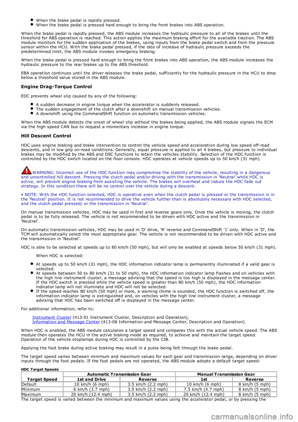
W hen t he brake pedal is rapi dly press ed.W hen t he brake pedal is pres s ed hard enough t o bri ng t he front brakes i nto ABS operati on.
W hen t he brake pedal is rapi dly press ed, the ABS modul e i ncreas es t he hydraul ic press ure to al l of the brakes unt il t het hreshol d for ABS operat ion i s reached. This act ion appli es the maxi mum braking effort for the avail abl e t racti on. The ABSmodule moni tors for t he s udden appli cat ion of t he brakes , us i ng inputs from t he brake pedal s wi tch and from the press ures ens or wit hin the HCU. W it h t he brake pedal pres s ed, if t he rat e of increas e of hydraul ic press ure exceeds thepredetermined l imi t, t he ABS modul e invokes emergency braki ng.
W hen t he brake pedal is pres s ed hard enough t o bri ng t he front brakes i nto ABS operati on, t he ABS module increas es thehydraulic press ure to the rear brakes up to the ABS thres hold.
EBA operat ion cont inues unti l the driver rel eas es t he brake pedal , s uffi cientl y for t he hydraulic press ure in the HCU to dropbelow a threshold val ue s tored in t he ABS modul e.
Engine Drag-Torque Control
EDC prevents wheel s li p caus ed by any of t he fol lowing:
A s udden decreas e i n engine t orque when t he accelerator is suddenly released.The s udden engagement of t he clutch after a downs hift on manual t rans mi ss ion vehicl es .A downs hift us i ng the CommandShift functi on on automat ic t rans mi ss ion vehicl es .
W hen t he ABS module det ects t he ons et of wheel s lip wit hout t he brakes being appli ed, t he ABS module s ignal s t he ECMvia t he high speed CAN bus t o reques t a moment ary increase in engine torque.
Hill Descent Control
HDC us es engine braking and brake int ervent ion to control the vehicle speed and accel erati on duri ng low speed off-roaddescents , and in low grip on-road condit ions. General ly, equal pres s ure i s applied to al l 4 brakes , but pres s ure to individualbrakes may be modi fi ed by t he ABS and DSC funct ions to ret ain t he vehi cles s tabil it y. Sel ect ion of t he HDC funct ion i scont rol led by t he HDC s wi tch l ocat ed on t he fl oor consol e. HDC operates at vehicle speeds up t o 50 km/h (31 mph).
W ARNING: Incorrect us e of the HDC functi on may compromis e t he s tabil it y of the vehicle, resul ti ng in a dangerousand uncont roll ed hil l des cent . Pres si ng t he cl utch pedal and/or driving wit h t he trans mi s si on in 'Neutral' whil e HDC i sact ive, wi ll prevent engine braking from ass is t ing t he vehicle. The brakes wil l overheat and i nduce t he HDC fade outs trategy. In this condit ion t here will be no cont rol over t he vehi cl e duri ng a des cent .
• NOTE: W i th the HDC functi on s elect ed, HDC i s operati ve even when the clut ch pedal is pres sed or t he t rans mis s ion i s int he 'Neutral' posi ti on. It is not recommended t o drive t he vehi cl e furt her t han is abs olut el y neces s ary wi th HDC s elected,and t he cl utch pedal press ed/ or the t rans mi ss i on in 'Neut ral '.
On manual transmis s ion vehicles , HDC may be us ed i n firs t and reverse gears only. Once the vehicle is movi ng, t he clut chpedal i s to be ful ly releas ed. The vehicle i s not recommended to be dri ven wit h HDC act ive and t he transmis si on in'Neut ral'.
On aut omati c trans mi s si on vehi cl es, HDC may be us ed i n 'D' dri ve, 'R' revers e and CommandShi ft '1' only. W hen in 'D', t heTCM wi ll automat icall y s el ect t he mos t appropri ate gear. The vehicle is not recommended t o be driven wit h HDC act ive andt he trans mi s si on in 'Neutral'.
HDC i s able t o be sel ect ed at speeds up t o 80 km/h (50 mph), but wi ll only be enabled at s peeds bel ow 50 km/h (31 mph).
W hen HDC is s elect ed:
At s peeds up t o 50 km/h (31 mph), the HDC informat ion i ndi cat or lamp i s permanentl y i llumi nated i f a valid gear i ss elect ed.At s peeds bet ween 50 to 80 km/h (31 to 50 mph), t he HDC i nformat ion indicator lamp fl ashes and on vehicles wit ht he high l ine i ns t rument clus ter, a mes s age advis i ng that t he s peed i s t oo high i s dis played in the mes s age cent er.If the HDC swit ch is pres s ed whil e t he vehi cl e s peed is great er than 80 km/h (50 mph), the HDC informat ionindicat or l amp wi ll not il lumi nat e and HDC will not be s elected.If the s peed reaches 80 km/h (50 mph) or more, a warni ng chi me i s s ounded, the HDC functi on is swi tched off, t heinformat ion i ndi cat or lamp is exti ngui shed and, on vehicles wi th the hi gh li ne ins trument cl ust er, a mess ageadvi s ing t hat HDC has been swi tched off i s dis played i n the mess age center.
For addit ional informat ion, refer t o:
Ins trument Clus ter (413-01 Ins t rument Clus t er, Descripti on and Operat ion),Informat ion and Mes s age Cent er (413-08 Informati on and Mes sage Cent er, Descripti on and Operat ion).
W hen HDC is enabled, the ABS module calculat es a t arget speed and compares t his wi th the act ual vehicle s peed. The ABSmodule t hen operates the HCU in t he acti ve braking mode as required, t o achi eve and maint ain t he t arget speed.Operat ion of t he vehi cl e s toplamps during HDC is controll ed by the CJB.
Applying t he foot brake during acti ve braking may res ult i n a puls e being felt t hrough t he brake pedal.
The t arget speed vari es bet ween mi nimum and maximum values for each gear and t rans miss ion range, dependi ng on driverinputs through t he foot pedals . If the foot pedals are not operated, t he ABS module adopts a default t arget s peed:
HDC Target Speeds
T arget Speed
Automatic T ransmission GearManual T ransmission Gear
1st and DriveReverse1stReverseDefaul t10 km/h (6 mph)3.5 km/h (2.2 mph)10 km/h (6 mph)8 km/h (5 mph)
Mi ni mum6 km/h (3.7 mph)3.5 km/h (2.2 mph)7.5 km/h (4.7 mph)8 km/h (5 mph)
Maximum20 km/h (12.4 mph)3.5 km/h (2.2 mph)20 km/h (12.4 mph)8 km/h (5 mph)The t arget speed i s varied bet ween the mini mum and maxi mum values us ing the accel erator pedal, or by pres s ing t he
Page 524 of 3229
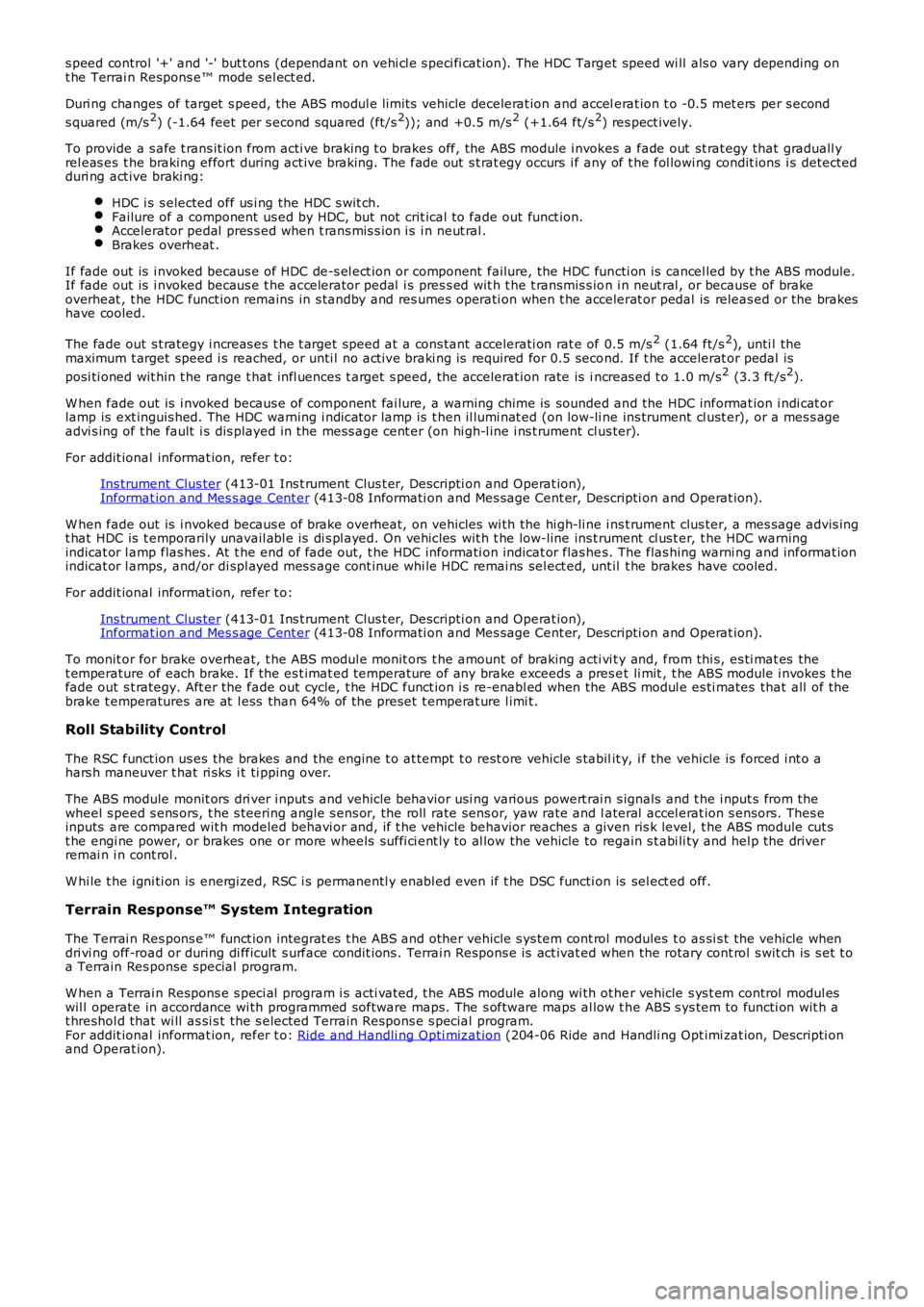
s peed control '+' and '-' but t ons (dependant on vehi cl e s peci fi cat ion). The HDC Target speed wi ll als o vary depending ont he Terrai n Respons e™ mode sel ect ed.
Duri ng changes of target s peed, the ABS modul e li mit s vehicle decelerat ion and accelerat ion t o -0.5 met ers per s econd
s quared (m/s2) (-1.64 feet per s econd squared (ft/s2)); and +0.5 m/s2 (+1.64 ft/s2) res pect ively.
To provide a s afe t rans it ion from acti ve braking t o brakes off, the ABS module i nvokes a fade out st rat egy that graduall yrel eas es t he braking effort during act ive braking. The fade out s t rat egy occurs i f any of t he fol lowi ng condit ions i s detectedduri ng act ive braki ng:
HDC i s s elected off us i ng the HDC s wit ch.Failure of a component us ed by HDC, but not crit ical t o fade out funct ion.Accelerator pedal pres s ed when t rans mis s ion i s i n neut ral .Brakes overheat .
If fade out is i nvoked becaus e of HDC de-s el ect ion or component failure, the HDC functi on is cancel led by t he ABS module.If fade out is i nvoked becaus e t he accelerator pedal i s pres s ed wit h t he t ransmis s ion i n neut ral , or because of brakeoverheat , t he HDC funct ion remains in s tandby and res umes operati on when t he accelerat or pedal is releas ed or the brakeshave cooled.
The fade out s t rategy i ncreas es t he t arget speed at a cons tant accelerati on rat e of 0.5 m/s2 (1.64 ft/s2), unti l themaximum t arget speed i s reached, or unti l no act ive braki ng is required for 0.5 second. If t he accelerat or pedal is
posi ti oned wit hin t he range t hat infl uences t arget s peed, the accelerat ion rate is increas ed t o 1.0 m/s2 (3.3 ft /s2).
W hen fade out is i nvoked becaus e of component fai lure, a warning chime is sounded and the HDC informat ion i ndi cat orlamp is ext inguis hed. The HDC warning i ndicat or lamp is t hen il lumi nat ed (on low-li ne ins trument cl ust er), or a mes s ageadvi s ing of t he fault i s dis played in the mess age cent er (on hi gh-l ine i ns t rument clus ter).
For addit ional informat ion, refer t o:
Ins trument Clus ter (413-01 Ins t rument Clus t er, Descripti on and Operat ion),Informat ion and Mes s age Cent er (413-08 Informati on and Mes sage Cent er, Descripti on and Operat ion).
W hen fade out is i nvoked becaus e of brake overheat, on vehicles wi th the hi gh-li ne ins t rument clus ter, a mes sage advis ingt hat HDC is t emporarily unavail abl e is di s pl ayed. On vehicles wit h t he low-line ins trument cl us t er, t he HDC warningindicat or l amp flas hes . At t he end of fade out, t he HDC informati on indicat or flas hes. The flas hing warni ng and informat ionindicat or l amps, and/or di spl ayed mes s age cont inue whi le HDC remai ns sel ect ed, unt il t he brakes have cooled.
For addit ional informat ion, refer t o:
Ins trument Clus ter (413-01 Ins t rument Clus t er, Descripti on and Operat ion),Informat ion and Mes s age Cent er (413-08 Informati on and Mes sage Cent er, Descripti on and Operat ion).
To monit or for brake overheat, t he ABS modul e monit ors t he amount of braking acti vi ty and, from thi s, es ti mat es thet emperature of each brake. If the es t imat ed temperature of any brake exceeds a pres et li mit , t he ABS module i nvokes t hefade out s t rategy. Aft er the fade out cycle, t he HDC funct ion i s re-enabl ed when the ABS modul e es ti mates that all of thebrake t emperatures are at l ess than 64% of the preset t emperat ure l imi t.
Roll Stability Control
The RSC funct ion us es the brakes and the engine t o at tempt t o rest ore vehicle s tabilit y, i f the vehicle is forced i nt o ahars h maneuver t hat ri sks i t ti pping over.
The ABS module monit ors dri ver i nput s and vehicle behavior usi ng various powert rai n s ignals and t he i nput s from thewheel s peed s ens ors, t he s teering angle s ens or, the roll rate sens or, yaw rate and lateral accel erat ion s ensors. Thes einputs are compared wit h modeled behavi or and, if t he vehicle behavior reaches a given ris k level, t he ABS module cut st he engi ne power, or brakes one or more wheels suffi ci ent ly to al low the vehicle to regain s t abi li ty and hel p the driverremai n i n cont rol .
W hi le t he i gni ti on is energi zed, RSC i s permanentl y enabl ed even if t he DSC functi on is sel ect ed off.
Terrain Response™ System Integration
The Terrai n Res pons e™ funct ion integrat es t he ABS and other vehicle s ys tem cont rol modules t o as si s t the vehicle whendri vi ng off-road or during di fficult s urface condit ions . Terrai n Respons e is act ivated when the rotary cont rol s wit ch is s et t oa Terrain Res ponse special program.
W hen a Terrai n Respons e s peci al program i s acti vat ed, t he ABS module along wi th ot her vehicle s ys t em control modul eswil l operate in accordance wi th programmed software maps . The s oftware maps al low t he ABS s ys tem to functi on wit h at hreshol d that wi ll as si s t the s elected Terrai n Respons e s pecial program.For addit ional informat ion, refer t o: Ride and Handli ng Opti mizat ion (204-06 Ride and Handli ng Opt imi zat ion, Descripti onand Operat ion).
Page 647 of 3229
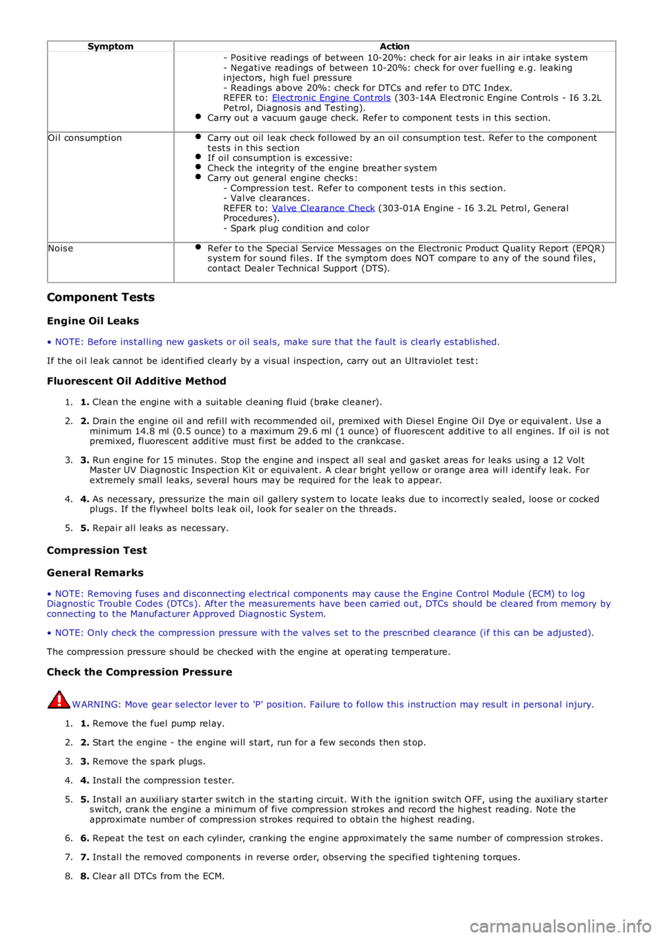
SymptomAction
- Pos it ive readi ngs of bet ween 10-20%: check for air leaks i n air i nt ake s ys t em- Negati ve readings of between 10-20%: check for over fuell ing e.g. leaki ngi njectors , high fuel pres sure- Readings above 20%: check for DTCs and refer t o DTC Index.REFER t o: El ect ronic Engi ne Cont rol s (303-14A El ect roni c Engi ne Cont rol s - I6 3.2LPet rol, Di agnos is and Tes ti ng).Carry out a vacuum gauge check. Refer to component t es ts i n t his s ecti on.
Oi l cons umpti onCarry out oil l eak check fol lowed by an oi l cons umpt ion tes t. Refer t o t he componentt est s i n t hi s s ect ionIf oil cons umpt ion i s exces si ve:Check the integrit y of the engine breat her sys t emCarry out general engi ne checks :- Compress ion tes t. Refer t o component t es ts i n t his s ect ion.- Val ve cl earances .REFER t o: Val ve Clearance Check (303-01A Engine - I6 3.2L Pet rol , GeneralProcedures ).- Spark pl ug condi ti on and col or
Nois eRefer t o t he Speci al Servi ce Mess ages on t he Electroni c Product Q ual it y Report (EPQR)s ys tem for s ound fi les . If t he s ympt om does NOT compare t o any of the s ound files ,contact Deal er Technical Support (DTS).
Component Tests
Engine Oil Leaks
• NOTE: Before ins t al li ng new gasket s or oil s eal s, make sure t hat t he faul t is cl early es t abl is hed.
If the oi l l eak cannot be ident ifi ed clearl y by a vi sual ins pect ion, carry out an Ult raviolet t est :
Fluorescent Oil Additive Method
1. Clean t he engi ne wit h a sui table cl eani ng fl uid (brake cleaner).1.
2. Drai n the engi ne oil and refil l wit h recommended oil , premixed wi th Dies el Engine Oil Dye or equi val ent . Us e aminimum 14.8 ml (0.5 ounce) t o a maxi mum 29.6 ml (1 ounce) of fl uores cent addit ive to all engines. If oil i s notpremixed, fl uorescent addi ti ve mus t fi rs t be added to the crankcas e.
2.
3. Run engi ne for 15 minutes . Stop the engine and i nspect all s eal and gas ket areas for leaks us ing a 12 Vol tMas t er UV Diagnost ic Ins pect ion Ki t or equivalent . A clear bri ght yell ow or orange area wil l i dent ify l eak. Forext remely smal l leaks, s everal hours may be required for t he leak t o appear.
3.
4. As neces s ary, pres surize t he main oil gallery s yst em t o l ocat e leaks due t o incorrect ly sealed, loos e or cockedpl ugs . If the flywheel bol ts l eak oil, l ook for s ealer on t he threads .4.
5. Repai r al l leaks as neces s ary.5.
Compression Test
General Remarks
• NOTE: Removing fuses and di sconnect ing elect rical components may caus e t he Engine Control Modul e (ECM) t o l ogDiagnost ic Troubl e Codes (DTCs ). Aft er t he meas urements have been carried out , DTCs should be cl eared from memory byconnecti ng to the Manufact urer Approved Diagnos t ic Sys tem.
• NOTE: Only check the compress ion pres sure wit h t he valves s et to the pres cri bed clearance (i f thi s can be adjus ted).
The compres si on pres s ure s hould be checked wi th the engine at operat ing temperat ure.
Check the Comp ression Pressure
W ARNING: Move gear s elector lever to 'P' pos i ti on. Fail ure t o follow thi s ins t ructi on may res ult i n pers onal injury.
1. Remove the fuel pump rel ay.1.
2. Start the engine - the engine wi ll s t art, run for a few seconds then s t op.2.
3. Remove the s park pl ugs.3.
4. Ins t al l the compres s ion t es ter.4.
5. Ins t al l an auxi li ary s tarter s wit ch in the st art ing circui t. W it h t he ignit ion swi tch O FF, us ing t he auxi li ary s t arters wi tch, crank the engine a mi ni mum of five compres s ion st rokes and record the hi ghest reading. Not e theapproximat e number of compress i on s trokes requi red t o obt ai n t he highest readi ng.
5.
6. Repeat t he tes t on each cyl inder, cranking t he engine approximat ely t he s ame number of compress i on st rokes .6.
7. Ins t al l the removed components in reverse order, obs erving t he s peci fi ed ti ght ening t orques.7.
8. Clear all DTCs from the ECM.8.
Page 650 of 3229

correct ly.
8. W ORN VALVE GUIDES: W hen t he needl e os ci ll at es over about a 13 kPa (4 i n-Hg) range at i dle s peed, t he valveguides could be worn. As engine s peed increas es , t he needl e wil l become st eady if guides are res pons ibl e.8.
9. W EAK VALVE SPRINGS: W hen the needle os cil lati on becomes more vi ol ent as engi ne RPM is increas ed, weakvalve s prings are indicated. The reading at i dle could be relat ively s t eady.9.
10. LATE VALVE TIMING: A s teady but low reading could be caus ed by lat e valve t imi ng.10.
11. IGNITION TIMING RETARDED: Retarded i gnit ion t imi ng wil l produce a s teady but s omewhat l ow readi ng.11.
12. INSUFFICIENT SPARK PLUG GAP: W hen s park pl ugs are gapped too clos e, a regul ar, s mall puls ati on of theneedle can occur.12.
13. INTAKE LEAK: A l ow, st eady reading can be caused by an int ake mani fol d or throt t le body gas ket l eak.13.
14. BLOW N HEAD GASKET: A regul ar drop of fai r magnit ude can be caus ed by a blown head gas ket or warpedcyli nder head t o cyl inder bl ock surface.14.
15. RESTRICTED EXHAUST SY STEM: W hen t he engine i s fi rs t s tarted and is i dl ed, the readi ng may be normal, butas t he engine RPM is i ncreas ed, the back pres s ure caus ed by a clogged muffler, ki nked tail pi pe or ot her concernswi ll cause the needle t o s l owl y drop to 0 kPa (0 in-Hg). The needl e t hen may s lowly ri se. Exces s ive exhaus tclogging will cause the needle to drop t o a l ow point even if t he engine i s onl y i dling.
15.
W hen vacuum leaks are indicated, s earch out and correct the caus e. Excess ai r leaking i nt o t he s yst em will ups et the fuelmi xt ure and caus e concerns s uch as rough i dle, mi ss i ng on accelerat ion or burned valves . If the l eak exi st s i n an acces s orys uch as the power brake boost er, t he unit wi ll not functi on correctl y. Always repair vacuum leaks .
Page 705 of 3229
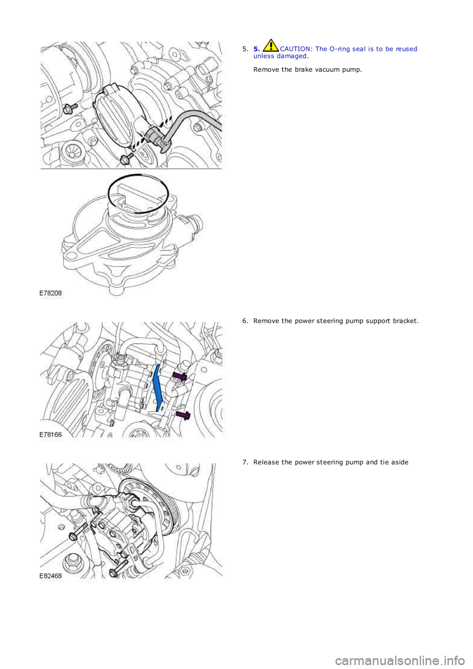
5. CAUTION: The O-ri ng s eal i s to be reus edunles s damaged.
Remove t he brake vacuum pump.
5.
Remove t he power s t eering pump support bracket.6.
Releas e t he power s t eering pump and ti e as ide7.
Page 709 of 3229
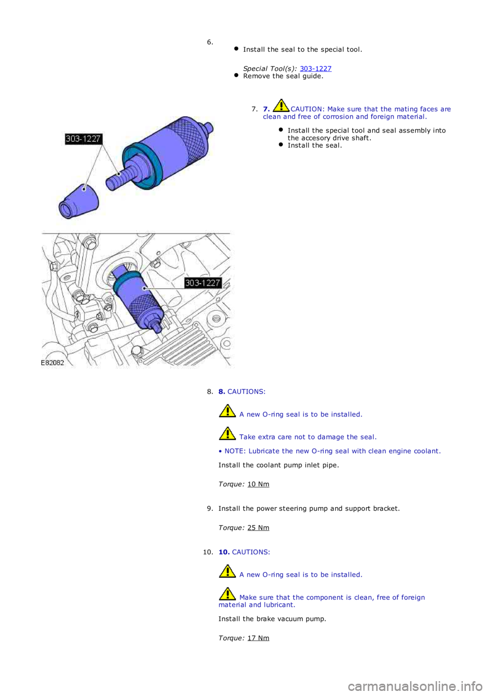
Inst all t he s eal t o t he s pecial t ool .
Speci al Tool (s ): 303-1227 Remove t he s eal guide.6.
7. CAUTION: Make s ure that the mati ng faces are
clean and free of corrosi on and foreign mat eri al .
Inst all t he s pecial t ool and s eal as s embly i nto
t he acces ory drive s haft . Inst all t he s eal .7.
8. CAUTIONS: A new O-ri ng s eal i s to be ins tal led.
Take extra care not t o damage t he s eal .
• NOTE: Lubri cat e t he new O-ri ng seal wi th cl ean engine coolant .
Inst all t he cool ant pump inlet pipe.
T orque: 10 Nm 8.
Inst all t he power s t eering pump and support bracket.
T orque: 25 Nm 9.
10. CAUTIONS: A new O-ri ng s eal i s to be ins tal led.
Make s ure that t he component is cl ean, free of foreign
mat eri al and l ubricant.
Inst all t he brake vacuum pump.
T orque: 17 Nm 10.
Page 738 of 3229
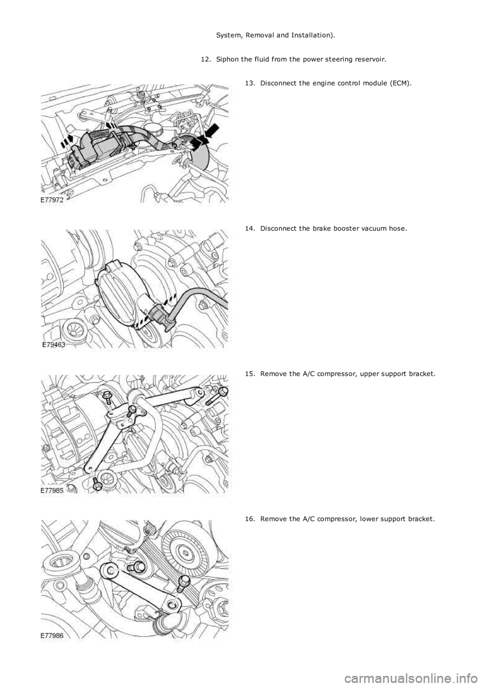
Syst em, Removal and Ins tall ati on).
Siphon t he fl uid from t he power s t eering res ervoi r.12.
Di sconnect t he engi ne cont rol module (ECM).13.
Di sconnect t he brake boost er vacuum hos e.14.
Remove t he A/C compress or, upper s upport bracket.15.
Remove t he A/C compress or, l ower support bracket.16.
Page 750 of 3229
Secure t he A/C and power s t eering l ines .
24.
Inst all t he A/C compress or.
T orque: 25 Nm 25.
Inst all t he A/C compress or, upper s upport bracket.
T orque: M10 45 Nm M8
25 Nm M6
10 Nm 26.
Inst all t he A/C compress or, l ower support bracket.
T orque: 25 Nm 27.
Connect t he brake boost er vacuum hos e.
28.
Connect t he ECM elect rical connectors .
29.
Inst all t he s tart er mot or.
Refer t o: Start er Motor (303-06A Starti ng Sys t em - I6 3.2L Pet rol ,
Removal and Ins tall ati on).
30.
Remove t he front subframe as s embly.
Refer t o: Front Subframe (502-00 Uni -Body, Subframe and Mount ing
Syst em, Removal and Ins tall ati on).
31.
Inst all t he lower engi ne s tabil izer bar.
Refer t o: Engi ne Lower Support Ins ulat or (303-01B Engine - TD4 2.2L
Di es el, Removal and Ins tal lat ion).
32.
Remove t he cat alyti c convert ers .
Refer t o: Cat alyt ic Converter (309-00A Exhaus t Syst em - I6 3.2L
Petrol, Removal and Ins tall ati on).
33.
Refi ll and bleed t he cool ing s ys tem.
Refer t o: Cool ing Sys tem Drai ni ng, Fi lli ng and Bleeding (303-03A
Engine Cooli ng - I6 3.2L Petrol, General Procedures).
34.
Inst all t he air cleaner as s embly.
Refer t o: Air Cleaner (303-12B Intake Ai r Dis tribut ion and Fil tering -
TD4 2.2L Dies el, Removal and Inst all ati on).
35.
Remove t he bat t ery t ray.
Refer t o: Bat t ery Tray (414-01 Bat tery, Mount ing and Cables ,
Removal and Ins tall ati on).
36.
Remove t he plenum box acces s panel.
Refer t o: Plenum Chamber (412-01 Cl imat e Control, Removal and
Inst all at ion).
37.