Page 1471 of 3229

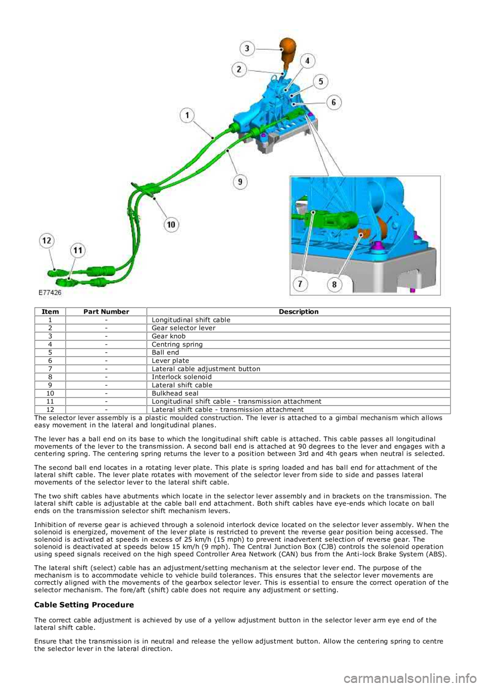
ItemPart NumberDescription
1-Longit udi nal s hift cabl e2-Gear s elect or lever
3-Gear knob
4-Centring spring5-Ball end
6-Lever pl ate
7-Lateral cable adjust ment butt on8-Interlock s ol enoi d
9-Lateral shi ft cabl e
10-Bulkhead s eal11-Longit udi nal s hift cabl e - t ransmis s ion at tachment
12-Lateral shi ft cabl e - t rans mis s ion at t achment
The s elect or lever ass embly is a pl ast ic moulded cons t ructi on. The l ever i s att ached t o a gi mbal mechanis m which all owseasy movement i n t he lat eral and longit udi nal pl anes .
The lever has a ball end on i ts bas e t o which t he l ongi tudinal s hi ft cable i s at tached. This cable pas s es all longit udinalmovements of t he lever to the t rans mi ss i on. A second ball end is at t ached at 90 degrees t o t he lever and engages wit h acent eri ng s pring. The cent eri ng s pring returns the lever t o a pos it ion bet ween 3rd and 4t h gears when neut ral is sel ect ed.
The s econd ball end l ocat es in a rot at ing lever pl ate. This pl at e i s s pring loaded and has bal l end for att achment of t helat eral s hi ft cable. The lever plat e rot ates wi th movement of t he s elect or lever from s ide to si de and pass es l at eralmovements of t he s elect or lever to the l ateral s hift cabl e.
The t wo s hift cables have abutment s which l ocat e in the s elect or l ever as s embl y and i n bracket s on t he t rans mis s ion. Thelat eral s hi ft cable is adjus t abl e at the cable bal l end att achment . Bot h s hift cabl es have eye-ends which l ocat e on ballends on the trans mi s si on s el ect or s hi ft mechanis m levers .
Inhi bi ti on of revers e gear is achieved t hrough a s olenoid i nterlock devi ce locat ed on t he s elect or lever ass embly. W hen thes olenoi d i s energized, movement of t he lever pl ate is rest ri cted t o prevent the revers e gear pos it ion bei ng acces sed. Thes olenoi d i s act ivat ed at speeds in exces s of 25 km/h (15 mph) t o prevent inadvert ent s electi on of revers e gear. Thes olenoi d i s deact ivated at s peeds bel ow 15 km/h (9 mph). The Cent ral Junct ion Box (CJB) control s t he s ol enoi d operat ionus ing s peed si gnal s received on t he high speed Controller Area Network (CAN) bus from t he Ant i-lock Brake Sys tem (ABS).
The lat eral s hi ft (s elect) cable has an adjus t ment/s et t ing mechani s m at t he s elect or lever end. The purpos e of t hemechani sm i s to accommodate vehicl e to vehi cl e buil d tol erances . This ens ures t hat the s elector l ever movements arecorrect ly ali gned wit h t he movement s of t he gearbox s el ect or lever. This i s es sent ial to ens ure the correct operat ion of t hes elect or mechani sm. The fore/aft (s hi ft ) cabl e does not require any adjust ment or s et t ing.
Cable Setting Proced ure
The correct cabl e adjus tment i s achi eved by use of a yel low adjust ment butt on in the s elect or l ever arm eye end of t helat eral s hi ft cable.
Ensure t hat t he t rans mis s ion i s in neut ral and rel ease the yell ow adjus t ment but ton. All ow t he cent eri ng s pring t o centret he sel ect or lever i n t he lat eral direct ion.
Page 1559 of 3229

1
2
3
1
2
3
4
5
6
7
1
2
1
Is a bl ockage or res t ri ct ion evident?YesCLEAR/REPAIR t he blocked or rest ri cted fuel l ine and t es t the s ys tem for normal operat ion.NoCHECK for DTCs and s ymptoms indicati ng anot her caus e for t he problem.REFER t o: Electroni c Engi ne Controls (303-14A Electroni c Engine Controls - I6 3.2L Pet rol , Diagnos i sand Tes t ing).
PINPOINT TEST B : CHECK THE FU EL SYSTEM PRESSURE
T ESTCONDIT IONSDET AILS/RESULT S/ACT IONS
B1: CHECK T HE PUMP ACT IVIT YRemove the rear s eat cus hion.REFER t o: Rear Seat Cus hi on (501-10 Seat ing, Removal and Inst all ati on).
Set i gni ti on s tat us to ON, engi ne OFF.
Li s ten for pump nois e.
Can the fuel pump be heard runni ng?YesGO t o B2.NoCHECK for DTCs .REFER t o: Electroni c Engi ne Controls (303-14A Electroni c Engine Controls - I6 3.2L Pet rol , Diagnos i sand Tes t ing).
B2: CHECK T HE FUEL SYST EM PRESSURE
W ARNING: This procedure invol ves fuel handl ing. Be prepared for fuel s pi ll age at al l ti mes andal ways obs erve fuel handli ng precaut ions . Fai lure to fol low t hese ins truct ions may res ul t in pers onali njury.
Make sure t he vehi cl e is in Park and apply the parki ng brake.
Set i gni ti on s tat us to OFF
• NOTE: Pl ace sui table abs orbent mat erial around t he Schraeder valve t o abs orb any spil lage whenconnect ing t he gauge set .
Connect adapt er 310-162 and gauge as sembl y 310-116 t o t he fuel Schraeder valve. Remove theabs orbent mat erial and dis pos e of safely.Dis connect and pl ug t he vacuum hos e from the press ure regulat or.
Open the valve on the fuel press ure gauge and adapter 310-116/162.
Set i gni ti on s tat us to ON, engi ne OFF.
Record the fuel press ure reading.
Is t he fuel pres s ure 3.6 - 4.2 bar (52.2 - 60.9 l b/in²)?YesGO t o B3.NoCHECK for DTCs .REFER t o: Electroni c Engi ne Controls (303-14A Electroni c Engine Controls - I6 3.2L Pet rol , Diagnos i sand Tes t ing).B3: CHECK T HE FUEL SYST EM PRESSURE WIT H T HE ENGINE CRANKING
Appl y foot brake and pres s s tart but t on.
Record the fuel press ure reading when engine cranki ng.
Is t he fuel pres s ure 3.6 - 4.2 bar (52.2 - 60.9 l b/in²)?YesGO t o B4.NoCHECK for DTCs .REFER t o: Electroni c Engi ne Controls (303-14A Electroni c Engine Controls - I6 3.2L Pet rol , Diagnos i sand Tes t ing).B4: CHECK T HE FUEL SYST EM PRESSURE WIT H T HE ENGINE IDLING (WHERE PO SSIBLE)
W it h engine runni ng.
Is t he fuel pres s ure 3.6 - 4.2 bar (52.2 - 60.9 l b/in²)?YesCHECK for DTCs and s ymptoms indicati ng anot her caus e of the probl em.REFER t o: Electroni c Engi ne Controls (303-14A Electroni c Engine Controls - I6 3.2L Pet rol , Diagnos i sand Tes t ing).NoCHECK the fuel pump module power and ground circui ts .
Page 1563 of 3229
Releas e t he adjus ti ng nut and di sconnect t he parkingbrake cables from the compens at or.4.
Fold t he RH rear s eat cus hi on forwards .5.
Releas e t he carpet and remove t he grommet .6.
Vehicles with fuel fired heater
7. CAUTIONS:
Ext reme cl eanli ness must be exerci sed whenhandl ing t hese components .
Make s ure that all openings are sealed. Us e newblanking caps.
7.
All vehicles
Page 1567 of 3229
Releas e t he parking brake cables from t he fuel tankcradle.19.
Remove t he fuel li ne cover.20.
21. CAUTIONS:
Ext reme cl eanli ness must be exerci sed whenhandl ing t hese components .
Make s ure that all openings are sealed. Us e newblanking caps.
Di sconnect t he 2 fuel l ines.
21.
Vehicles with fuel fired heater
Page 1571 of 3229
Refi ll t he fuel t ank.2.
Adjus t t he parking brake.
Refer t o: Parking Brake Cabl e Adjus tment (206-05 Parking Brake andActuat ion, General Procedures ).
3.
Page 1582 of 3229

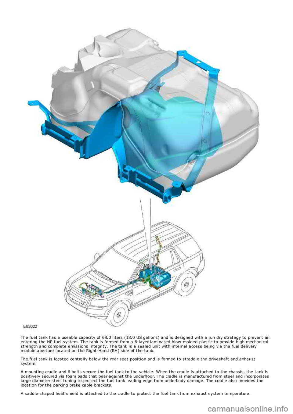
The fuel t ank has a useable capaci ty of 68.0 li ters (18.0 US gal lons) and i s des igned wit h a run dry s trat egy t o prevent ai rentering t he HP fuel s ys tem. The t ank is formed from a 6-layer lami nat ed blow-molded pl as t ic t o provi de high mechani cals trengt h and complet e emis s ions i ntegri ty. The t ank is a sealed uni t wit h i nt ernal acces s being via the fuel del iverymodule apert ure locat ed on t he Right -Hand (RH) s ide of t he tank.
The fuel t ank is l ocat ed cent rall y below the rear s eat posi ti on and is formed to s traddl e the drives haft and exhaus ts ys t em.
A mount ing cradl e and 6 bolt s s ecure t he fuel tank t o t he vehi cle. W hen t he cradle is at tached to the chass i s, t he t ank isposi ti vel y s ecured via foam pads t hat bear agai nst t he underfl oor. The cradle is manufact ured from st eel and incorporateslarge diamet er s t eel t ubing t o prot ect t he fuel t ank leading edge from underbody damage. The cradle al so provides thelocati on for t he parking brake cable bracket s .
A s addle s haped heat s hiel d is at t ached t o t he cradle t o prot ect the fuel t ank from exhaust s ys tem temperature.
Page 1595 of 3229
Releas e t he adjus ti ng nut and di sconnect t he parking
brake cables from the compens at or.
4.
Fold t he RH rear s eat cus hi on forwards .
5. Releas e t he carpet and remove t he grommet .
6.
Vehicles with fuel fired heater 7.
CAUTIONS: Ext reme cl eanli ness must be exerci sed when
handl ing t hese components . Make s ure that all openings are sealed. Us e new
blanking caps.
7.
All vehicles
Page 1599 of 3229
Releas e t he parking brake cables from t he fuel tank
cradle.
19. Remove t he fuel li ne cover.
20. 21.
CAUTIONS: Ext reme cl eanli ness must be exerci sed when
handl ing t hese components . Make s ure that all openings are sealed. Us e new
blanking caps.
Di sconnect t he 2 fuel l ines.
21.
Vehicles with fuel fired heater